











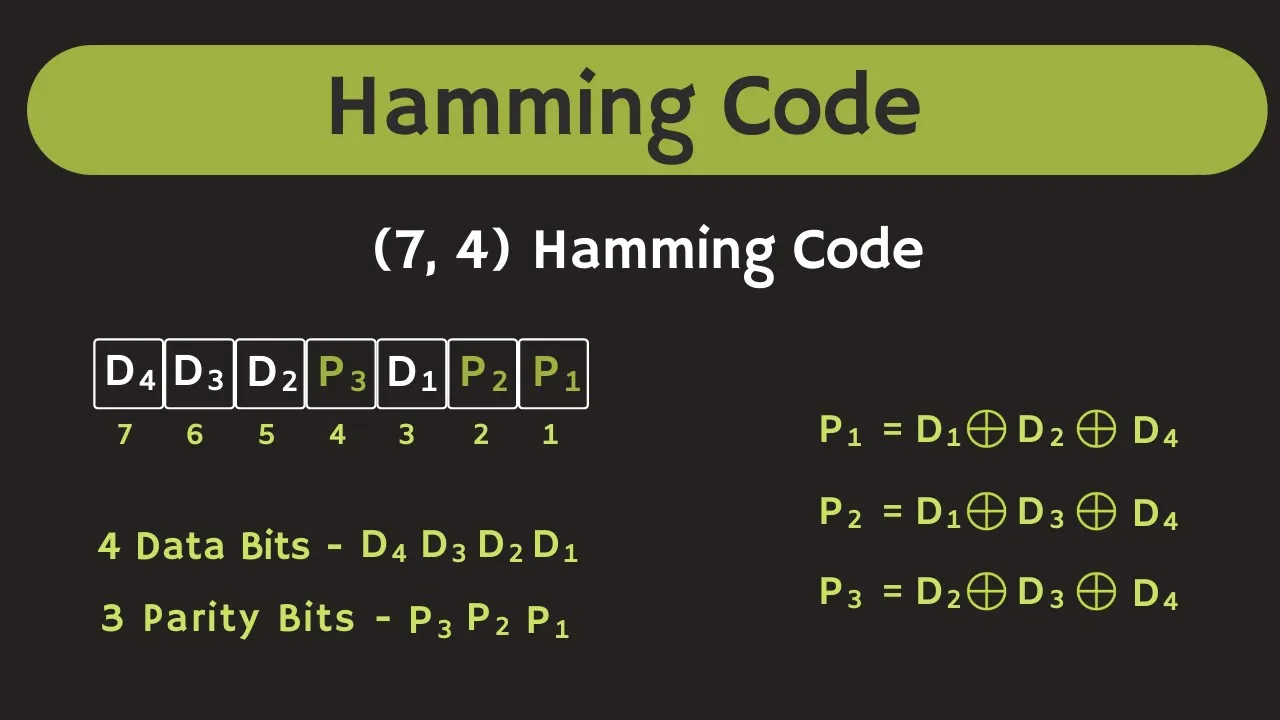






Hamming Code is an error detection method developed by Richard W. Hamming that uses parity bits strategically placed at positions that are powers of two (1, 2, 4, 8...) to detect and identify single-bit errors in transmitted data; in a 7-bit Hamming Code, three parity bits (P1, P2, P4) are calculated based on specific data bits (P1 covers D3, D5, D7; P2 covers D3, D6, D7; P4 covers D5, D6, D7), and the receiver detects errors by comparing calculated parity values with received ones, with the error position determined by the binary combination of parity bit errors.
Hamming Code Error Detection Explained | Digital Electronics Tutorial
Added:Basic understanding of the binary number system and binary representation of data.
The concept of parity (even and odd parity) and its use in basic error detection.
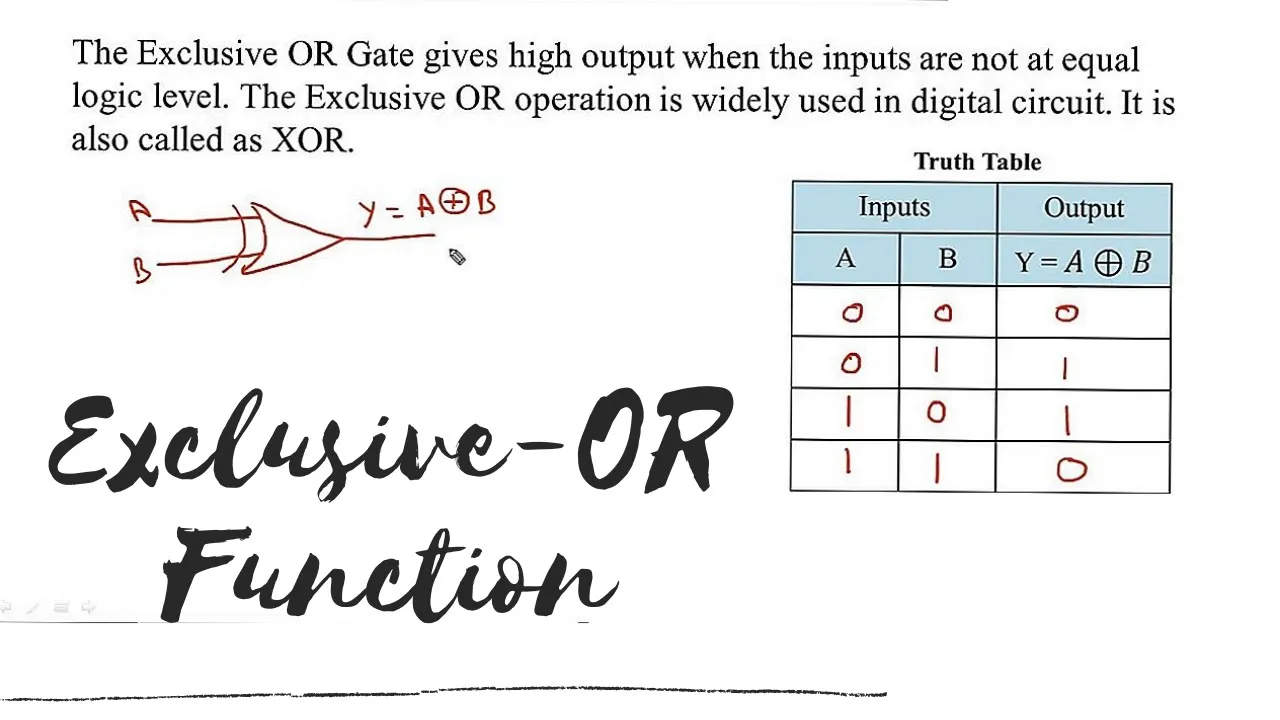
Familiarity with digital logic gates, particularly the exclusive-OR (XOR) operation used for parity generation.
Fundamental concepts of digital data transmission and how noise causes bit errors.
Single Error Correction, Double Error Detection (SEC-DED) using extended Hamming codes.
Cyclic Redundancy Check (CRC) algorithms for more robust error detection in modern network protocols.
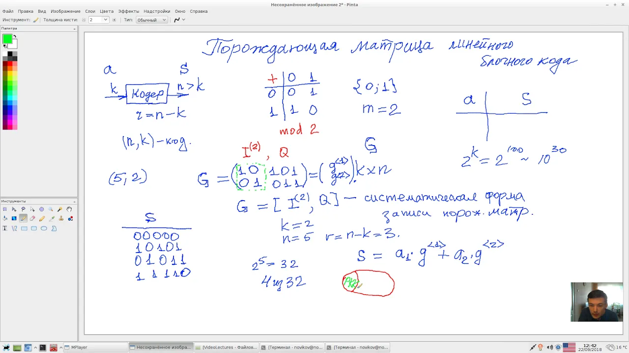
Linear block codes and the mathematical matrix representation (generator and parity-check matrices) of encoding and decoding.
Advanced Forward Error Correction (FEC) schemes such as Reed-Solomon codes and Convolutional codes used in modern communication.
2.4M views22.3Klikes12:19Original Release: 2015-01-20
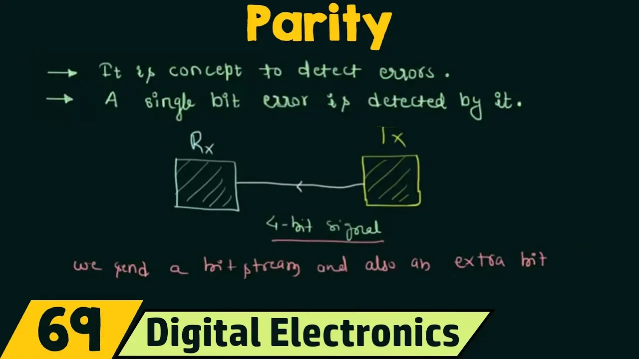
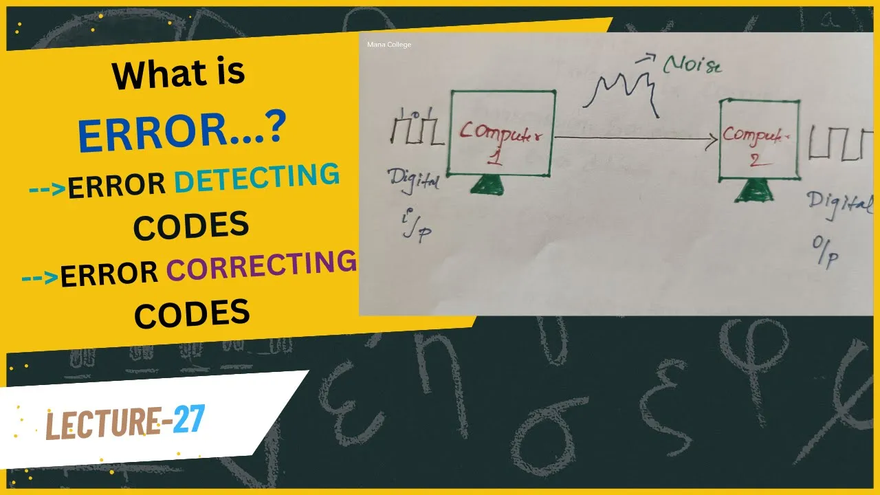
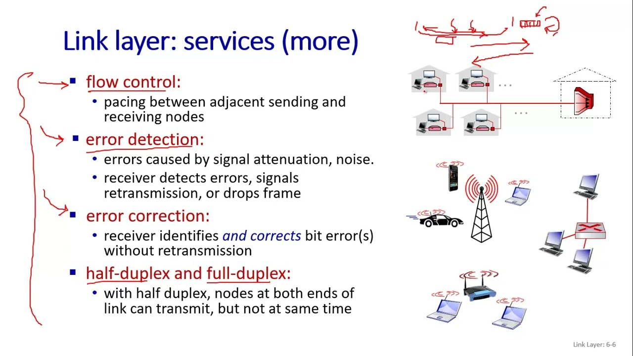
[music] In this presentation we will study about the Hamming code. I have divided Hamming code into two presentations. In this particular presentation we will see what is Hamming code and how it is used to detect the error. Which means we are going to do the basic of the Hamming code and see one example in which we will try to detect the error. In the next presentation we will see the error correction part of the having code. So it is a very easy thing to understand for you. And uh if you remember in the very beginning of this course I explained you that if a data is being transmitted from the transmitter and received by the receiver there is a channel between the transmitter and the receiver and uh in that channel there is a very much possibility of the noise being added to our data and this will distort our data and that we don't want.
So the error detection and correction is a very important aspect in the digital electronics and it's a very important thing for you to understand at this particular point in this course. So let's move to the basic of the Hamming code. It was given by RW Hamming the name of the scientist and on his name only we call this code as the Hamming code. It is very easy to implement.
Okay, you will see it's a very easy thing to implement. And a seven bit Hamming code, a seven- bit Hamming code is used commonly, but definitely you can have a Hamming code greater than the seven bit. But in this presentation, we will try to focus on the seven bit Hamming code. Okay, here you can see that I have made seven bits. But till now we cannot call it a Hamming code because we have not followed the instructions or the rules given by the RW Hamming. Okay. So what are the rules that we have to follow to make this seven bit a hamming code. The first thing that you should know is the data bits. Data bits. And the second thing you should know is the parity bit. Parity bits. Okay. Now most of you might be thinking then what is this parity bit?
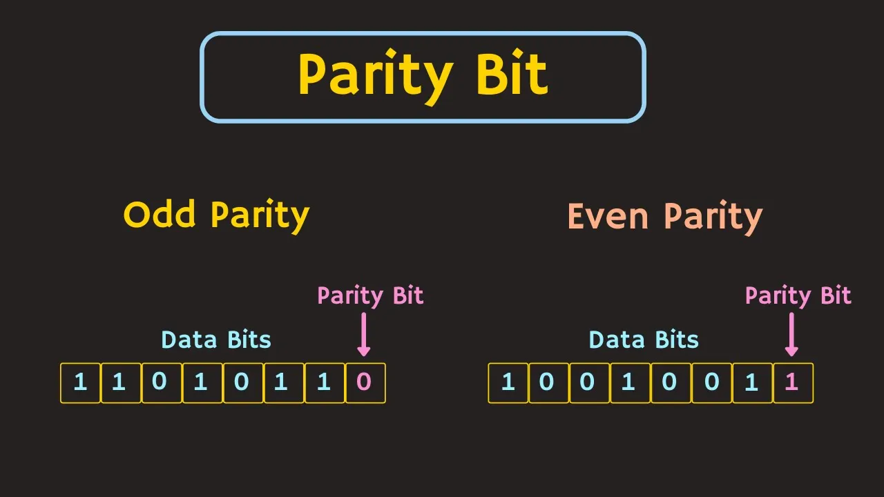
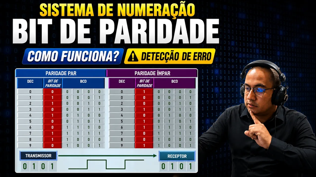
You know the data bit the data that you want to transmit. And uh the question is what is this parity bit? So let me tell you the parity bit is nothing but the extra bit stream that we send along with the database to detect the error. Okay.
So this parity bit is sent along with this data bit and in case of Hamming code we are having three parity bit and four data bit particularly in case of seven bit Hamming code. Okay. When you are having the greater bit in the Hamming code, they may vary. Okay, the parity bit will change. But in seven bit Hamming code, we are having three parity bit and four data bit. Okay, now we have to decide the position in this seven bit for the database and the parity bit that what will be the position for the parity bit and what will be the position for the datab bit. So how we are going to find this thing out? We will find it by a simple thing given by RW Hamming. He told us that 2 to the power n where where n is equal to 0 1 up to n will be the position for the parity bits. Okay. So let me put n equal to0. So 2 having power equal to0 gives us what? one and uh before doing this let me give the name to this bit 1 2 3 4 5 6 and then 7.
Okay. So the first bit will be our parity bit because 2 to the^0 gives us 1. So this one is our parity bit and I will call it P1.
Okay. Now I will put n equal to 1. So two having power one gives us two. So this second bit is also our parity bit.
I will give it name p2.
And then two having power two gives us four. So this is our fourth bit. And this fourth bit is your p4.
Okay. Now two having power three gives you eight. And we don't have the eighth bit. So we will stop here. Okay. But if you were having the more bits in the Hamming code, you have to put the P8 as our parity bit. So we will stop here.
And the rest of the bit that you can see here is our data bit. This one is our first data bit. We will call it D3.
This is our second data bit. D5.
D6 D7.
Okay. So this particular arrangement that you can see here is your Hamming code. Okay. Now we have to see how to operate on this particular code. P1 depends upon the value of D3, D5 and D7.
Which means if we are working on the even parity then if the value of D3 is zero D5 is 1 and D7 is zero. So to make it the even parity we have to make the value of P1 1 because you can see that the number of one in this four bits is even. Similarly for P2 it depends upon D3 D6 D7 and P4 it depends upon D5 D6 D7.
Okay. And uh this was given by RWM. So you have to remember this thing that P1 is associated with D3 D5 D7. P2 is associated with D3, D6, D7 and P4 is associated with 5, 6 and 7. So I think it's clear for you. So it's time to move for one example. Let us suppose I want to transmit a 4bit data having the values 1 0 1 1. Okay. Now depending upon this data, we have to determine the values of your P1, P2 and P4. So let me make uh seven bit having code for this particular example.
[snorts] This is your seventh bit. Sixth fifth bit fourth bit third and one. So let's see how many bits we are having. 1 2 3 4 5 6 7 8. So we need to remove one bit.
Now we are having the seven bits. Okay, out of this you already know that this one, this one, this one and this one is your data bit. So this will be one because we are having the D7 as one.
This is zero. This is one and this is one. Fine. And uh this is your P1, P2, P4. We have to determine the values of P1, P2 and P4. So let's do it. P1 [snorts] will depend upon what? D3, D5, D7. So let's see the values of D3, D5 and D7.
So let me write it down first. This is your D3. This is your D5, D6, D7. So D3 is one. So one and D5 is also one. Okay. Okay. And D7 is also one. So there are total three bits and which are odd. So we have to make P1 equal to 1. Okay. To make it as the even parity. If you're working for the odd parity, then P1 will be zero. So P1 will be 1. Similarly, if I see for P2, I have to see D3, D6, D7. So D3 is 1, D3 is 1, D6 is zero and D7 is 1. So we are having the even bits and we are working for the even parity. So P2 is zero. So I will make zero here. Similarly for P3 I have to see D5, D6, D7, D5 is 1, D6 is zero and D7 is 1. So again we are having the even number of ones. So P3 will also be sorry this is your P4. P4 is also zero. So P4 is zero. So what we have to send from this is this is your receiver. This is your channel and this one is your transmitter. So what we will send? We will send 1 0 1 0 1 0 1. Okay. In this this three and this one is your data bit and this 0 0 and one is your parity bit.
Okay. And this bit stream is being sent from receiver to transmitter. Now the transmitter will receive this bit stream and he will do the analysis for the error detection. So how is he going to detect the error? Let's see. Let's say noise has been added in the channel and uh the transmitted bit stream is now one one 0 1 0 1. Okay. So what is the effect of noise in this bit stream is that at this position we were having zero but because of the noise we are having one now.
Okay. So the receiver will see the parity bits. He will first check for P1.
So P1 is for what? P1 is for D3, D5 and D7. So he will check for the value of P1 and the value of P1 is one. It means that the number of bit in D3, D5 and D7 must be what? Odd. That's why we have made P1 as one to make it even. But in this case if I see D3 is having the value one. Good. D5 is having value 1 and D1 is having value one. So it is odd and we have added P1. So there is no problem in the P1. He will check now P2. P2 is for D3 D6 D7. D3 is 1, D3 is 1, D6 is 1 and D7 is 1. So they are odd. Okay. But the value of P2 here you can see is zero. And we are sending a even parody. So it must be one in this case to make it even because there are odd number of ones. So he will know that there is what an error in the bit out of what? D3 D6 D7. He now knows that there is error. Similarly he will check for P4 and P4 is for D5 D6 D7 and the value of P4 is zero.
P5 is 1. P6 is 1 and P7 is one. Again the value of P4 must be one because in even parity it must be one to make it even but it is zero again.
So again he knows that there is error in this 5 6 7. So this is how he detects the error by checking for the parity bit. In the next presentation we will see how to correct the error. to see you in the next one.
Up Next

8:27
Understanding Perfect Error-Correcting Codes: Hamming Distance Explained
@Computerphile
577.3K views•2017-03-08
87:26
Introduction to Secure Multiparty Computation with Yehuda Lindell
@fhe_org
7.7K views•2021-02-04
14:19
Compiler Design Introduction: Phases & Architecture Explained
@nesoacademy
560.3K views•2022-03-26
19:25
Enigma Machine Mechanics: WWII Encryption Explained
@JaredOwen
13.2M views•2021-12-11
Related Study Plans & Knowledge Roadmaps
Structured learning paths in Computer Science
computer-science
Container Runtimes: Namespaces, Cgroups & Go
01Linux Systems & Go Programming Foundations
02The Core of Isolation: Chroot and Filesystems
03Linux Namespaces: Process Isolation
+ 3 more learning modules
32h6 modules
Explore Roadmap
computer-science
Building a CHIP-8 Emulator: Rust & CPU Basics
01Computer Architecture Foundations (Bits & Bytes)
02Rust Programming for Systems Development
03CHIP-8 Virtual Hardware Specifications
+ 2 more learning modules
32h5 modules
Explore Roadmap
computer-science
Building BitTorrent: Go, P2P & Concurrency
01Go Fundamentals & Concurrency
02Networking Foundations & P2P Architecture
03Bencode Parsing & Torrent Metadata
+ 3 more learning modules
26h6 modules
Explore Roadmap
computer-science
Actor Models (C++ Concurrency & Lock-Free)
01C++ Multi-Threading Foundations
02Thread Pools and Task Scheduling
03Atomics and Lock-Free Queue Design
+ 3 more learning modules
45h6 modules
Explore Roadmap