Building a CHIP-8 Emulator: Rust & CPU Basics
Learning Goal: Designing and building a functional CHIP-8 emulator from scratch in Rust to master CPU instruction decoding, memory-mapped I/O, and keyboard-display peripheral interfacing.
- Prerequisites: Basic knowledge of programming concepts (variables, loops, and functions). No prior systems programming or hardware architecture experience is required.
- Estimated Total Study Time: 32 Hours
Module 1: Computer Architecture Foundations (Bits & Bytes)
This module introduces you to the core structural elements of computer architecture. You will learn how computers use binary to represent numbers, how registers store immediate computational states, how RAM is structured to store data and instructions, and how the Central Processing Unit (CPU) executes code via the Fetch-Decode-Execute cycle.
Recommended Videos
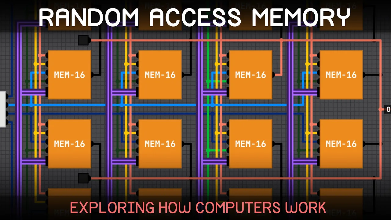
- Why this video: This video visually traces the transition from primitive logic gates to registers, and ultimately to full random-access memory systems. It provides a concrete mental model of how data is physically addressed and stored, which is essential for simulating a 4KB RAM layout in software.

- Why this video: Understand the CPU's internal storage. This video covers register functions, explaining how data, instruction addresses (Program Counters), and intermediate arithmetic results are managed close to the ALU.

- Why this video: This video breaks down the core execution pipeline of any CPU: fetching an instruction from memory, decoding what operation needs to be run, and executing it. This is the exact software loop you will implement in your emulator.

- Why this video: Essential preparation for parser and interpreter logic. It teaches bit manipulation techniques such as bitwise AND, OR, XOR, and bit-shifting. These techniques allow you to isolate bits of an instruction (opcode) or toggle individual pixels.
Knowledge Checkpoint
- Understand how numbers are represented in binary (Base-2) and hexadecimal (Base-16).
- Describe the difference between standard RAM addressing and local CPU registers.
- Explain how the Program Counter (PC) guides the Fetch-Decode-Execute cycle.
- Demonstrate how to construct a bit mask to isolate a single nibble (4 bits) from a byte (8 bits).
Module 2: Rust Programming for Systems Development
This module transitions from architectural theory to implementation using Rust. You will set up your toolchain, learn the fundamentals of Rust syntax, master Rust’s memory ownership and borrowing models (which replace traditional garbage collection), and implement binary arithmetic and bit shifting using Rust operators.
Recommended Videos
- Why this video: A comprehensive primer on the Rust language toolchain (
rustcandcargo), primitive data types (integers, arrays, and slices), variables, and conditional execution structures required to build your program's foundation.

- Why this video: Breaks down Rust's borrow checker and Resource Acquisition Is Initialization (RAII). This explains how Rust guarantees compile-time memory safety without a garbage collector, which is crucial when handling memory arrays in emulators.

- Why this video: Focuses specifically on Rust's shifting operators (
<<,>>). You will use these operators to parse raw binary ROM files and shift opcodes into readable commands.
⚠️ Curriculum Note (Video Pool Gap): While general Rust courses cover syntax and toolchains well, they rarely dive deep into systems-level binary parsing (e.g., using
u16::from_be_bytesor slicing raw arrays).Actionable self-study instruction: To fill this gap, research how Rust handles casting with
asand byte slices. Practice usingstd::fs::Fileand reading data into a byte vector (Vec<u8>) representing your simulated system memory.
Knowledge Checkpoint
- Set up a new Rust project using Cargo and execute it.
- Explain how ownership and scoping work in Rust to prevent dangling pointers.
- Write a Rust function that takes a slice of bytes (
&[u8]) and parses them using shifting (<<) and masking (&). - Explain why variables are immutable by default in Rust and how to declare mutable states.
Module 3: CHIP-8 Virtual Hardware Specifications
This module covers the physical design of the target machine you are emulating. The CHIP-8 is an interpreted virtual machine designed in the mid-1970s. You will map out its specifications, including its 4KB memory allocation, 16 general-purpose 8-bit registers, 16-bit Index Register (), Program Counter (), stack system, and specialized timers.
Recommended Videos

- Why this video: Provides a complete structural breakdown of the CHIP-8 hardware platform. It defines how the 4096-byte memory space is partitioned, the role of the 16 8-bit registers (V0-VF), and how VF serves as a flag register for carry/borrow operations.

- Why this video: An excellent summary of the hardware components needed for a CHIP-8 emulator. It details the dimensions of the display buffer, the 16-key hexadecimal keypad layout, and how the delay and sound timers decrement at a constant rate of 60Hz.

- Why this video: Discusses emulator architecture, focusing on the core emulation loop, program load addresses, and handling display states in main memory.
⚠️ Curriculum Note (Video Pool Gap): Introductory overview videos often skip the exact memory-map coordinates of CHIP-8, such as where system assets like the built-in font set (sprites for 0-F) are stored.
Actionable self-study instruction: Refer to "Cowgod's Chip-8 Technical Reference". Implement the built-in hexadecimal font set (80 bytes total, 5 bytes per character) and load it into the first 512 bytes of your simulated 4096-byte memory array (typically addresses
0x000to0x1FF), as this area is traditionally reserved for interpreter internals.
Knowledge Checkpoint
- Map the entire CHIP-8 memory space ( to ) and explain where ROM code starts executing ().
- Explain the purpose of the 16-level stack and the Stack Pointer () in CHIP-8 subroutine calls.
- Describe the behavior of the Sound and Delay Timers and state their decrement frequency.
- Identify which 8-bit register functions as the arithmetic carry/collision flag.
Module 4: Building the CPU: Fetch, Decode & Execute
This module covers the core logic of your emulator: the CPU execution loop. You will implement a ROM file reader in Rust to load games into memory, construct a loop that fetches 2-byte opcodes, decode those instruction parameters using bit-masking patterns, and write Rust match statements to execute CHIP-8's arithmetic and flow control commands.
Recommended Videos
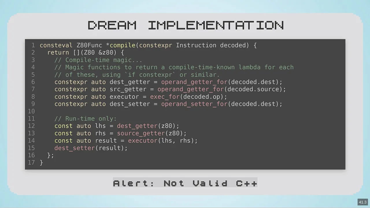
- Why this video: Legendary compiler engineer Matt Godbolt discusses the philosophy of emulating architectures cleanly. It covers decoupling instruction fetching, decoding, and dispatching, which helps keep your CPU code clean and maintainable.

- Why this video: Demystifies instruction decoding by illustrating how raw binary strings are parsed into executable commands. It provides a simple foundation for mapping byte sequences to operations.
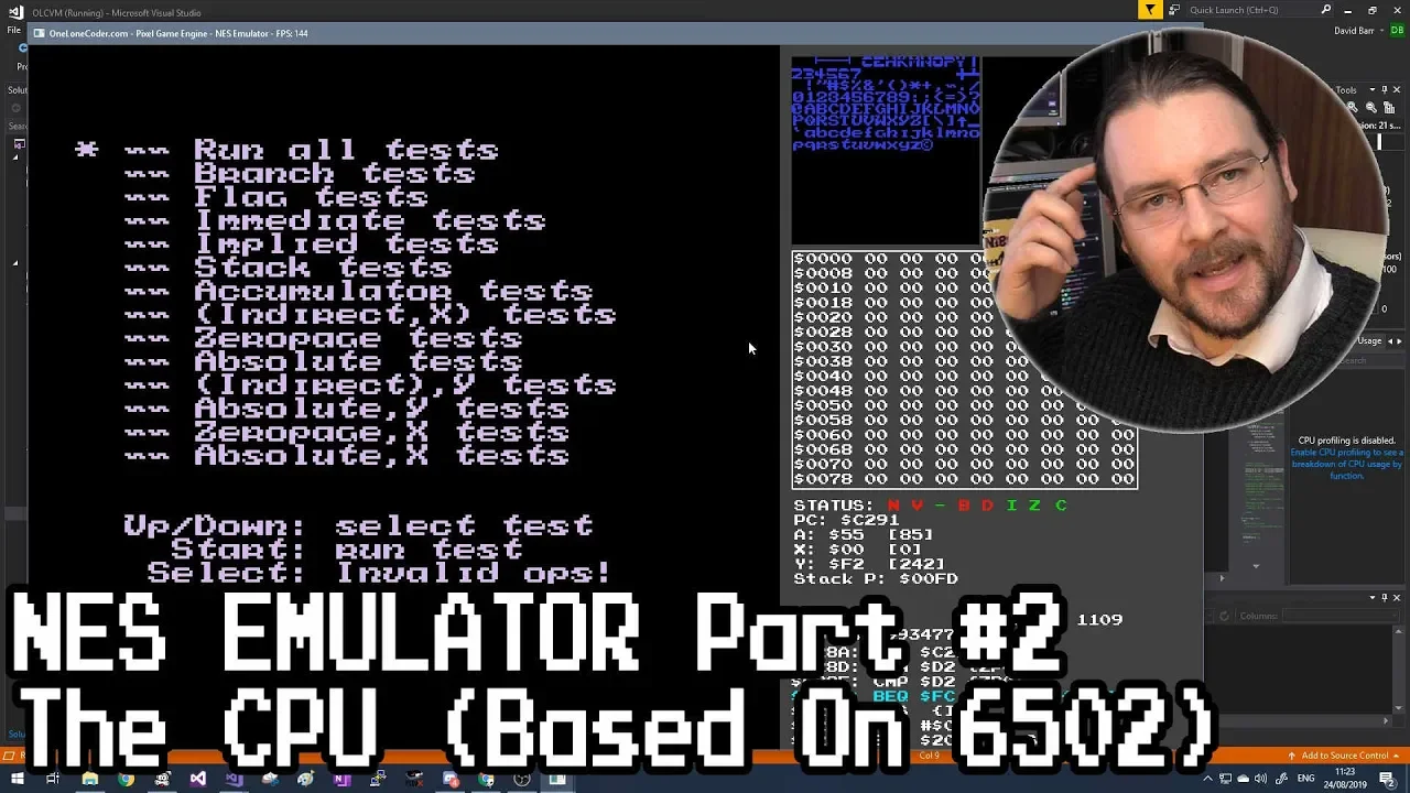
- Why this video: Although it focuses on the 6502 CPU, this video demonstrates the structural design of an emulator loop. It shows how to read memory values, execute opcodes, update instruction pointers, and handle execution cycles in code.
⚠️ Curriculum Note (Video Pool Gap): Existing videos lack a step-by-step Rust walkthrough for CHIP-8 instruction decoding and ROM parsing.
Actionable self-study instruction: Define a
Cpustruct in Rust containing memory ([u8; 4096]), registers ([u8; 16]), index register (u16), program counter (u16), stack ([u16; 16]), and stack pointer (u16). Since CHIP-8 instructions are 2 bytes long, construct each opcode by fetching two consecutive bytes from memory at the current Program Counter, then combine them using bitwise operations:let op_byte1 = memory[pc as usize]; let op_byte2 = memory[(pc + 1) as usize]; let opcode = ((op_byte1 as u16) << 8) | (op_byte2 as u16);Decode variables like (the second nibble) and (the third nibble) using shifts and masks:
let x = ((opcode & 0x0F00) >> 8) as usize;
let y = ((opcode & 0x00F0) >> 4) as usize;
Use a nested
matchblock on the isolated nibbles of the instruction to route execution to the appropriate logic (e.g.,0x8XY1for bitwise OR, or0x7XKKto add a constant).
Knowledge Checkpoint
- Implement a function in Rust that opens a local file and loads its contents into memory starting at address
0x200. - Combine two 8-bit memory values into a single 16-bit CHIP-8 opcode.
- Use bit masking to extract parameters , , , , and from an instruction.
- Implement conditional branch logic in Rust (e.g., handling the
3XKKinstruction, which skips the next instruction if registerVXequals the byteKK).
Module 5: Display Rendering, Keypad, and Sound IO
This final module focuses on interfacing your emulator with real human inputs and outputs. You will implement a game loop that updates at a steady frame rate, process keyboard state transitions, and draw graphics using standard windowing libraries like minifb or sdl2. You will also learn to handle CHIP-8’s unique XOR sprite drawing mechanism.
Recommended Videos
- Why this video: Shows how to configure window layers, capture keyboard events, and organize a multimedia-ready application lifecycle. While shown in C, the initialization architecture applies directly to Rust's window handling crates.
- Why this video: Explains CHIP-8's XOR graphics logic. It details how the emulator draws sprites at coordinates using data read from memory, and how it sets the carry flag (VF) to 1 if any active pixels are toggled off (collision detection).

- Why this video: Introduces the fundamental game loop structure in Rust (Load -> Update -> Render -> Events). It provides a mental framework for executing CPU cycles and refreshing the display at a constant frame rate.
⚠️ Curriculum Note (Video Pool Gap): Traditional reference videos use C/SDL2, which doesn't directly map to idiomatic Rust libraries like
minifborsdl2crate bindings.Actionable self-study instruction: Create a flat display array
[u8; 64 * 32]or[bool; 2048]in your CPU struct to represent pixels. When executing the Draw instruction (DXYN), read bytes of sprite data from memory starting at index . For each row, iterate through the 8 bits of that byte. If a bit is1, XOR it with the corresponding pixel in your display array. If this operation turns off an active pixel, setV[0xF] = 1. Use theminifbcrate in Rust to initialize a window, map your flat array to aVec<u32>buffer, and callwindow.update_with_buffer(&buffer, 64, 32)inside your core loop to render the graphics.
Knowledge Checkpoint
- Explain how XOR graphics rendering handles sprite drawing and collision detection.
- Map the physical keyboard layout of your host system to CHIP-8's 16-key layout (typically keys
1-4,Q-R,A-F, andZ-C). - Create a steady game loop in Rust that updates inputs, decrements timers at 60Hz, and runs CPU cycles.
- Write a rendering function that translates the CHIP-8 screen buffer to your window's pixel array.
Course Map
This map outlines your learning path and highlights the key technical milestones you will build along the way.
Key People Index
- Matt Godbolt (Presenter in Module 4): Veteran games developer, systems software architect, and creator of Compiler Explorer. He is a prominent educator on clean emulation techniques, compilation pipelines, and performant CPU instruction dispatching.
- Sebastian Lague (Presenter in Module 1): Software developer and educator known for highly visual, interactive software-to-hardware breakdowns. His videos make complex hardware concepts like register routing, logic structures, and memory addressing accessible to beginners.
Final Self-Assessment
Complete this checklist to verify your understanding and ensure your emulator is fully functional:
- Data Types: You understand binary representation and can perform bitwise manipulation operations in Rust using
&,|,^,<<, and>>. - Memory Allocation: Your emulator reserves a 4096-byte array for RAM and successfully loads the standard 80-byte CHIP-8 font set into the system reserved section.
- ROM Loading: Your program can read binary ROM files from disk and load them into memory starting at the standard entry address (
0x200). - Instruction Fetching: Your CPU loop fetches 2-byte opcodes at the address indicated by the Program Counter () and increments the counter by 2 after each step.
- Subroutine Stack: You have implemented working jump operations (
2NNNand0x00EE), pushing returning values onto the memory stack and restoring them using the stack pointer. - Registers: Your emulator models the 16 8-bit registers (V0-VF) and correctly sets VF as the flag register for arithmetic carry and display collision states.
- XOR Rendering: Your implementation of the Draw instruction (
DXYN) processes sprite byte sequences and uses XOR drawing logic to detect collisions, setting register VF to 1 when a pixel is toggled off. - Dynamic Timers: You have implemented both the Delay Timer and the Sound Timer, decrementing them at a steady rate of 60Hz.
- Peripheral Mapping: Your host keyboard successfully registers state changes and maps them to CHIP-8’s hexadecimal keypad layout.
- Loop Consistency: Your emulator runs at a stable execution speed (e.g., ~500Hz for CPU execution, 60Hz for display updates and timer decrements).