









![Verilog in 2 hours [English]](https://i.ytimg.com/vi_webp/nblGw37Fv8A/maxresdefault.webp)







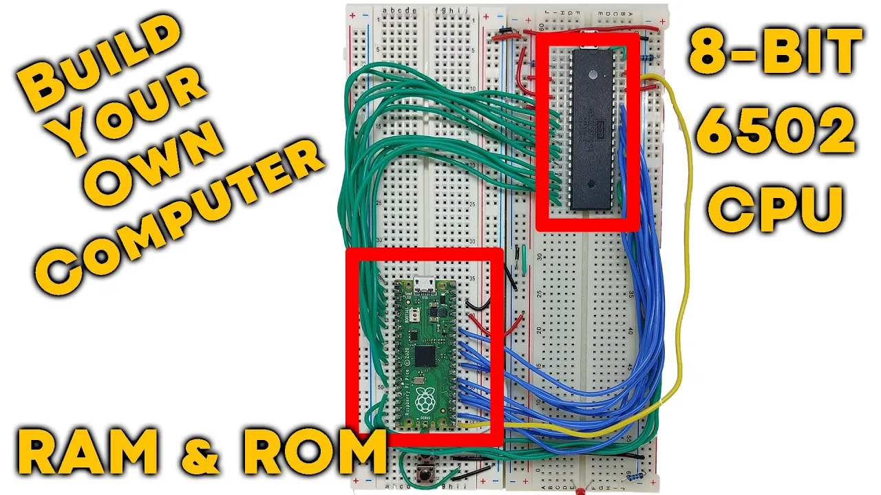


CPU emulation involves creating software that simulates a processor's behavior by implementing its instruction set, registers, memory, and I/O components, allowing developers to test custom CPU designs and assemblers without physical hardware; this can be achieved on microcontrollers like the Raspberry Pi Pico using microPython, where the emulator reads machine code from a binary file, decodes instructions, executes them by manipulating registers and memory, and displays output on an OLED screen.
Emulating a Custom CPU on Raspberry Pi Pico with MicroPython
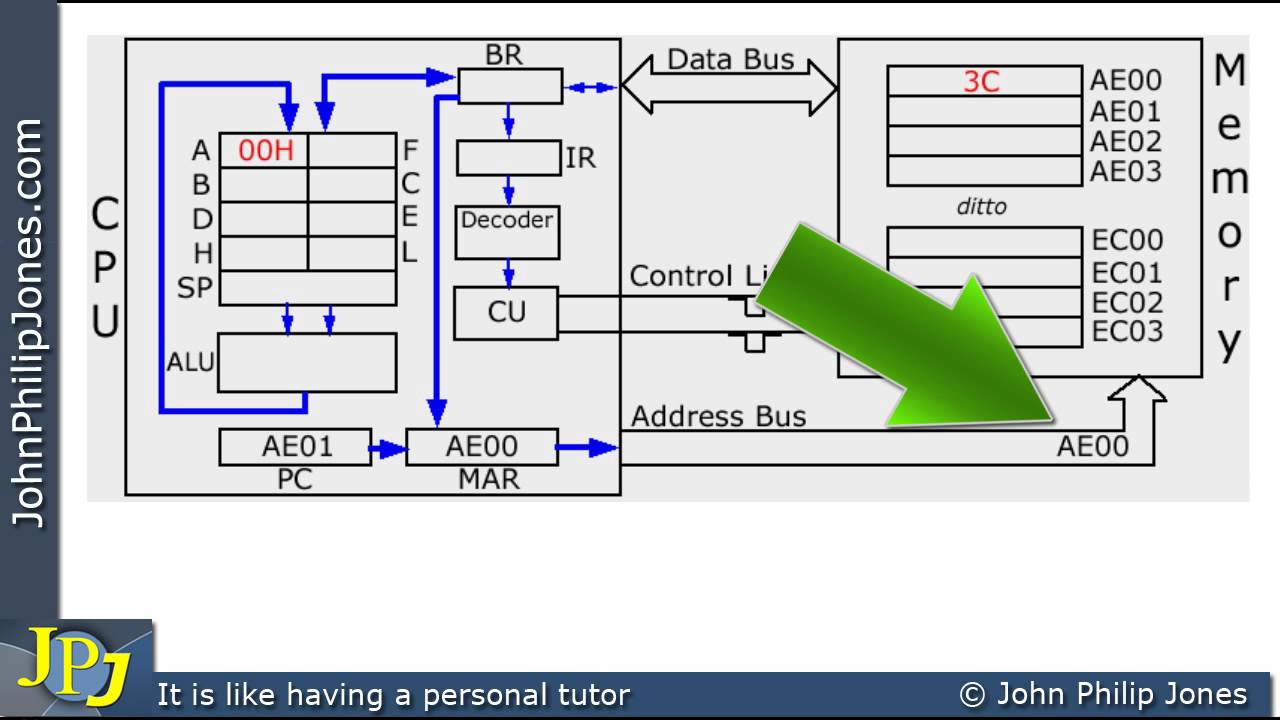
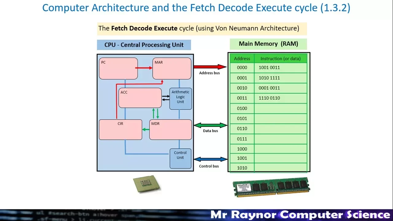
Added:Basic computer architecture concepts, specifically the Fetch-Decode-Execute cycle, registers, memory maps, and the Arithmetic Logic Unit (ALU).
Intermediate programming in Python or MicroPython, including familiarity with bitwise operations, byte manipulation, and basic data structures.
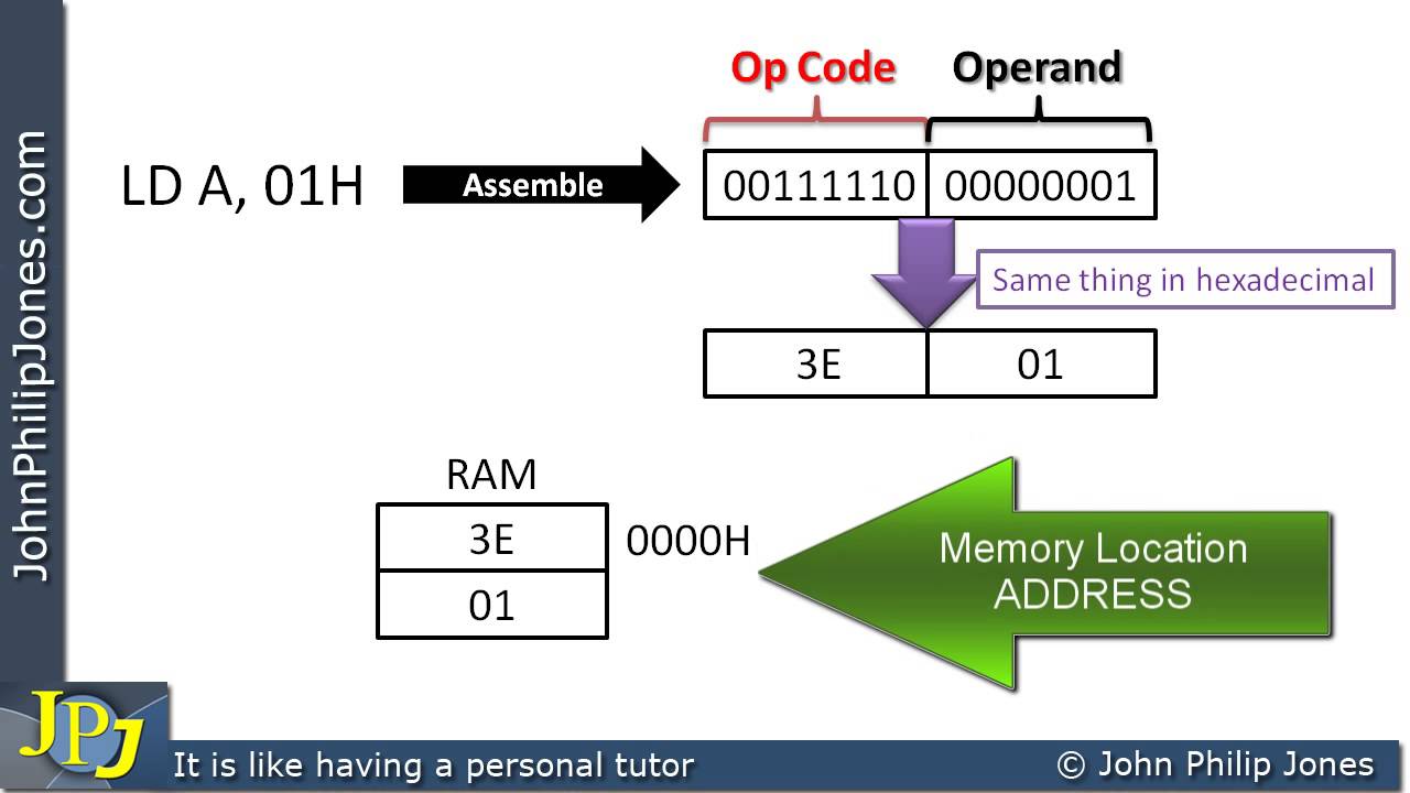
The fundamentals of assembly language and machine code, including how opcodes and operands are structured to form instructions.
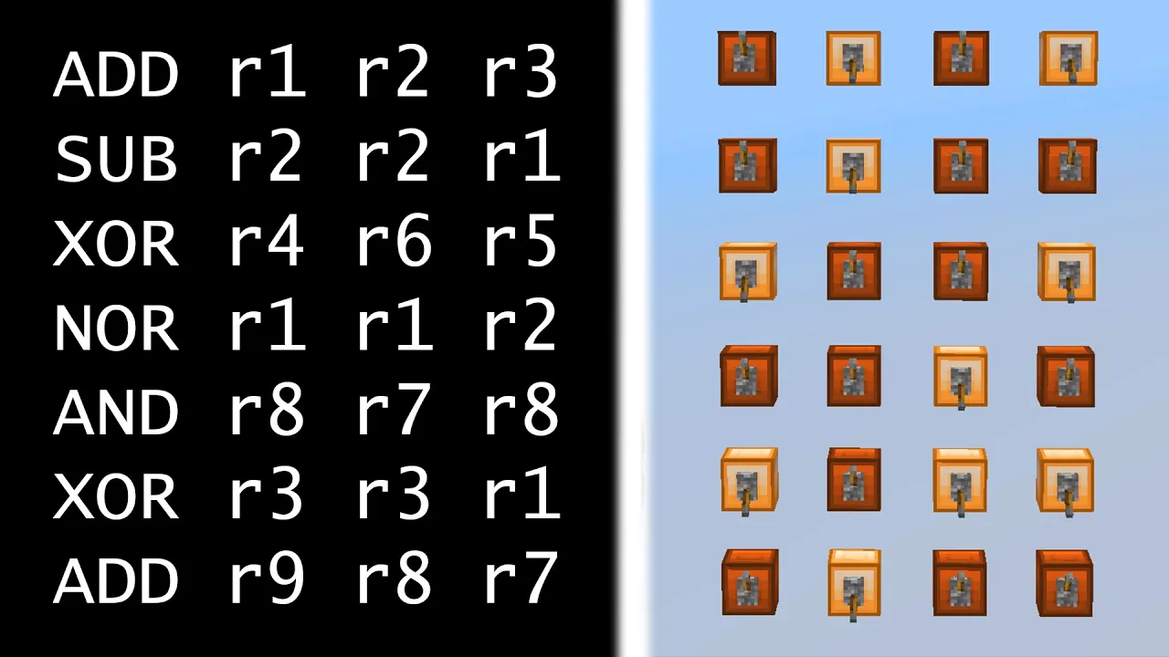
Implementing the custom CPU design in physical hardware using a Hardware Description Language (HDL) like Verilog or VHDL on an FPGA.
Writing a custom assembler or a simple high-level compiler (such as a basic C compiler) targeted specifically for this custom instruction set architecture (ISA).
Optimizing the emulator's performance on the RP2040, possibly by rewriting performance-critical parts of the emulator in C/C++ or using assembly.
Utilizing the Raspberry Pi Pico's Programmable I/O (PIO) blocks to interface the emulated CPU with physical external peripherals like RAM or displays.
53.4K views1.7Klikes32:17Original Release: 2022-04-07
hey there my name is gary sims and this is gary explained now i've got lots of videos here on this channel about how cpus work i've even got a video on how you can design your own cpu instruction set and then how you can write an assembler for that cpu instruction set and the video i needed to make after that was how you can emulate your own cpu in software so you can test out that instruction set and the assembler you have written and that's what we're going to do in today's video so if you want to find out more please let me explain okay now there are a few choices that we could come to when emulating our cpu design in software one is we could just do a python program that you run on the desktop linux mac windows whatever you like but i thought wouldn't it be fun to actually do it on a raspberry pi pico now of course the raspberry pi pico is a micro controller it has its own cpu in fact it has a dual core cpu has its own memory a flash memory very very sophisticated a piece of equipment but the thing of course when you look at it you know as you uh look at these things they actually look like the old cpus that used to get with the legs on them back in the day you know the 6502 the dialogue z80 and many many others so even the uh the microcontrollers that you have uh inside of the arduino kind of look like this so wouldn't it be fun if we could put our own instruction set and our own emulation onto one of those and then it can act like a a cpu in its own right now having made that decision there are two further decisions i could either actually build the whole system into that chip so the memories in that chip the cpus in that chip the display any kind of io is all built into that chip or we can actually try to build a system so you just emulate the cpu in one raspberry pi pico then another raspberry pi pico you might want to emulate the memory and then get them to talk to each other over some kind of bus in another one you might want to do some kind of general io chip that is able to do different things including driving a display and kind of build up a more kind of bigger system i opted for the first one for this first video because it's simpler just to implement the memory and the cpu and the display driver all inside of one python program that we're going to run on the raspberry pi pico if there's enough interest please tell me in the comments below and we can look about how you can emulate a much larger system with independent chips and we talk to them over a bus if there's enough interest in that i will certainly make a video okay so let's just crack on okay so if you remember from my last videos here is an overview of the instructions we defined for our virtual cpu that we're building for this thing we're designing and basically you've got some load instructions here at the top for how you can load in real numbers load from one bridge to another or loading things from memory then we have a set of store instructions that allow you to store from one register to another from memory and so on and again uh notice here it's 16 bits so we want to be able to do high and low because you want to just do one part of that 16 bit word in other words one bite of it then there's some compare stuff some branching based on what happened in the compare branch greater than branch less than and so on finally a little bit of mathematics add and subtract and then halt and no op which are also useful for throwing into a into a cpu architecture and then if you remember we wrote a com an assembler which takes assembly language and turns it into this machine code so for a quick look at that okay so here is a very simple assembly program in fact this is what we're going to use to test the cpu when we implement it what does it do it loads into register 1 65 which is ascii for the character a and then it loads into register 2 an address fbff in hex and in the cpu we're designing that is where i've decided to put the display memory so when you write to that address you're getting the first character of the display and then the next address will be the next character of the display and i'm using a three line display 48 characters in total and so if we look at how that's been translated into the actual machine code here is an output of the rom file that we're going to use zero zero well we know zero zero is in fact uh load in fact i've got a bit of the the table here again here it is so we know that load has got the op code zero zero and then into r1 would be in the second byte so if we flick back to here we can see into register one and then what you're putting in register one zero zero four one four one is the hex for 65. if we look at the next one we can see zero zero load again into what register two what are we putting in there fbff and of course that's exactly what we saw here and let's see if we can guess the next one 14 okay 1401.002 that's the next instruction there so let's go over to our disassembly so 14 scroll down here it is look so it's loading into regis two registers and so we saw it was one and two and if we go back to our program we can see here look register one and two so that's it so basically what we want to do is build a cpu that can take all these numbers is the machine code and understand them actually do those things so we need to emulate registers we need to emulate some memory and we need to emulate a display so that when thing goes into the memory it gets written out on the display so this is the the building blocks of emulating a cpu okay so as i said we're going to emulate this on a raspberry pi pico and we're going to be using micro python to do it so micro python uh needs a file called main.p why that's our main uh cpu emulator we're gonna use a few other files which we'll talk about shortly and we're gonna have an oled display attached so we've got a fully functioning uh system with memory cpu and a display so here's the program this will all be available of course in my github repository uh then we're gonna flash the led so here we've got a thing to set the led there are some flags here now there are a couple of modes that i've built into this debug is a pretty good one so when it runs it will just dump out onto this uh the output inside of micro python which is basically the serial output as well the standard output information about what the processor is doing the interactive mode allows you to step through so you can see every single instruction and then dump display true or false basically says as it runs should it just dump out what would be on the display the audio display again on the standard output and if you haven't got the display set up this is a good way of running this you don't need to have the ole the oled display you can actually just run this here inside of python in fact with a bit of tweak you can run it in any python configuration so we'll talk about those as we meet those registers so what am i as we meet those flags so what we're going to do basically we've got our cpu and the first thing we do we need to have some registers now our architecture allows us to have quite a lot of register actually because that second byte actually is a register number so we could actually have 255 registers if we wanted to but i've chosen just to make this simple we're going to just do it with seven registers to start with 15 kind of is the traditional one so i've said registers 8 to 15 are reserved really i suppose i should put in here something like you know r16 to uh r255 are reserved as well because we're not using them even though we could in our because of the way we've designed our architecture so what i've basically got is i've got registers here is basically a an array there that we can just change them we need a program counter where are we porting to in memory we need some memory itself so here is our how we're emulating the memory it's basically just a byte array of 64k and the last 1k starting at fbff as we saw from our assembly program here there's that same address look okay that is basically going to be this our character display so 64k of memory 1k of character display you can configure it however we want you could have much more memory you could have a different area for the display you could do the display in a different way this is how where i'm going to emulate it and then we need some flags because when you do things in a cpu like if you compare two things you need to have some flag so we need a is it zero flag is it greater than flag and is it less than flag and this is the display start just a variable that just defines this fb ff so we can use it later on now i'm not going to talk about this oled display stuff at the moment we'll skip over that i'll come back to it later because that's not the important stuff really here for our cpu image again for this stuff here not worth looking at it for the moment we will do later okay so what do we got next a little function that prints out a number as a hex string four digits long so if it's one it will do zero zero zero one if it's uh 255 it will do zero zero ff so it basically prints out as four digits wide which is good for the debugging basically okay so what this next function does is it dumps out the display to the standard output if you remember up here we had a flag to say dump display so we can basically if we set that to true then the program will call this function and actually dump things to uh the display and what does it do it takes the start address which we know is that fbff address i've defined that if you're if you write this yourself you can put them the video memory wherever you want to i just put it in the last k and we know it's 48 characters long so it's six 16 characters three lines 48 bytes and what it basically does is it goes to main memory there we go we define main memory as an array this is basically how we're we are emulating main memory 64k of main memory here it takes that main memory and it basically looks inside of it and says oh uh is this uh is this a printable character a normal principle if it's less than 32 32 in ascii and utf-8 you need to look up an ascii table if you're not sure about that and the characters below it are non-printable if it's less than that then just print a space instead if it is a printable character then add it to our string and basically we just print out the string and we go around in a loop here are two loops one for the whole memory one for each line so three lines uh and for the whole memory and i print out these dashes at the beginning and the end to mark it out so really it just takes what's in those memory locations and dumps them out which gives us a very cheap and quick way of getting a display now the next one here again is for debug it's called dump registers and it will dump out the program counter the code that is at the program counter and the status of all the zeros r zero r one if we zipped it into this line all the way up to r seven they just get printed out and what are they with their registers r six is as simple as that registers uh index five it's as simple as that so that's how we're keeping the registers and also the flags what are the states of the zero flag the status of the um of the greater than flag and of the less than flag now one thing to notice is i do have this function here called disassemble now i've already i've got a module here called vdisassem.py okay this will also be in my github repository what it basically does is it goes through the code and works out the strict convert this from this hex back into this text okay that's what it does it takes this tech this this binary machine code and converts it back into this text and it's a disassembler and it just creates strings based on what the numbers are so if it's 0 0 we know that a load and then it works out which registry is and so on and that will be in the github repository and what this basically our main program is for debugging it says if i was to give you these op code and this data what would that be disassembled isn't it just basically a quick program now the actual cpu is very similar to the disassembler in that it has to recognize the code and do something with it rather than just create a string so look at that code at your leisure it basically just works out what zero zero is there that must be a load instruction what was one for well that must be that store instruction as we store as we saw earlier on and that's just good for decoding now the main bulk of it of this thing here is in this decode function that i've written now again all the op codes are available in that page that i showed up earlier on the very first page and just give us a reminder here everything is four bytes as we've already discussed the op code the first register if it's used and then two bytes for the data so load r1 um a b c d would be zero zero zero one in fact that would be there and then a b c d and so what do you do when you want to emulate the instruction it's really really simple you say what's the instruction okay so op remember is the op code shifts to the right because it's only the first byte this one we want and the first number we've actually read it is op code is actually the whole 16 bits we want the eight bits so you say what is the op code what is the mode that's why and that i mean what is this um register number okay and we're waiting to have a big if statement now there are clever ways of doing this you could look it up in tables you could look with a list you could have a dictionary there's a whole bunch of different ways but for real really make it easy you say if it's op code zero then we know it's a load okay so what do we do well we basically put data whatever was in that second uh 16 bytes we put it in the register so you know that really what is simple zero 0 1 a b c d will you put a b c d into register 1 which is what our whole machine code is that's this here well in this case it's 65 so loading to register 165 okay so what we're basically saying is registers put in the data now for real simplicity i don't do any sanity checking here look at this here need to sanity check the register like if the register was in was actually 255 which we've said already is reserved it should give an error saying i don't know what register 255 is in fact python may even crash itself because i haven't defined the registers array to be long enough so yes there could be way more checking going on here but i am assuming that our programs are healthy and good and i just want to show how simple it is to create the emulator writing all the checking uh it would add a layer of complexity which is necessary don't get me wrong it is necessary but this is what we need to get this working and then we say okay what's up code uh01 well we go back to our little list here that's also over there in github 01 is load between two registers so what it says is okay we need to load in register so it's register to register we just again take these two things and basically you go through all of these you're either manipulating the main memory or the register the main memory or the register that is basically what a cpu does it stores state different types of state either in the main memory or in a register and then it actions the next thing it's going to do based on that state and that's almost the kind of the the basic definition of a turing machine that it takes state and then does something based on that state in a modern day von neumann as they call them cpu does that not with the head that turing talked about and the ticker tape it does that with memory uh and registers okay now it might get a bit more complicated when we come down here to compare so in compare i've basically said the same thing i said if it's equal then set the flags to zero flag is yes and uh the greater than less than r0 now why do you say zero flag because in the old days a compare was really a subtract and if you subtract two numbers you take away 10 from 10 you get zero so you can actually do a compare by doing a subtract you don't actually even need a compare option as long as your subtract option your subtract code can actually set the flags for greater than less than or for zero depending on the the um subtract i'm actually going to use my own compare opt code we talked about that when i designed the actual thing and again i say the same thing if it's greater than then you set the flags accordingly if it's less than you set the flags accordingly same again when you're comparing a real number this was comparing two two uh registers same when you're comparing actual data with a number has it reached 10 in the loop for example and then basically branching there are now three branching four branchings branch equal and so basically if it was zero which means if it was the same if it was equal because 10 minus 10 is zero then just branch to the address in the branch command now if you look here in our program we've got a branch branch less than loop which takes you back up to here so branch less than loop what's that going to do here in our main program branch less than says if the less than flag is correct then just jump to loop now in our in our binary data we will see let's look at what the branch less than number is it is 32 so let's find the op code 32 and here it is okay so it says branch less than to where well to address zero zero eight and zero zero eight as we look back up here in our little program takes us back up to here that's where zero zero eight starts okay so that's what the loop uh is and the assembler works out all these addresses for you that's the great thing about the assembly works out all the addresses add and subtract same thing okay either add either subtract either add either subtract either data or registers registered data just depends on the mode so we just work our way through those and do that and finally halt jumps to the end of memory so the program counter becomes ffff and no op um doesn't do anything it just literally just ignores it because if it's not equal to no op then it must be illegally strike and nope is our last instruction if it's not equal to no op then it must be some kind of illegal instruction and so it prints out illegal if it is no or it will just loop round and that's basically it and so what we do in our main memory is we just literally open up rom.bin which is hard coded for the moment this is how our processor works it automatically owes up rom.bin and rom.bin is basically this file here this is a text version of it but it's this file actually in in binary numbers itself it opens it up loads it into our main array that's what it does there copies it into our main memory and then basically this is for interactive mode we'll talk about in a minute it basically says fetch the first 16 uh bits first two bytes fetch the second one here's all the stuff about debugging which you talked about later update the oled display with about that later but basically it says call the decode function now that will return the program counter why because if you have a branch you want to know where you're jumping to okay and then it just goes around a loop while the program counter is less than the end of the program we loaded in so we know how long it is here because we loaded it in from a binary file and it just keeps going round and round and round and round and round forever and ever and ever okay so we haven't mentioned the overlay display and we haven't mentioned the debugging but let's just run this program okay now uh we're going to have just dump displayed equal to true now let's just go back to the program what does it do it takes 65 takes the address of the memory okay stores okay whatever was in r1 into the rest of the memory compares to see whether we're at uh the end of uh 48 characters after 65 so what 65 plus 48 okay 112 and so if you haven't got to 112 then add one to r1 add one to r2 and then branch the compare was already done here branch if you can notice the compare set those flags add doesn't change those flags so we can do the compare and then we can do other instructions and the flags won't change then finally we say okay if it was the compare the last compare you did was less than then loop back up to here and it would go 65 that's capital a 66 capital b capital c capital d and they'll just keep on going like that until it gets to 112 which isn't the end of 48 carat 48 printable characters and then if that happens it will then drop down here it won't branch it then starts with 32 32 is space and it will reset the uh r2 back to the beginning of memory and actually it just goes around putting space so it blanks the display so basically this will fill the display with characters a b c d e f g h when it gets into the display it will fill it all with spaces and then finally an actual branch takes us back to the start which is zero and if we look at our code here we can see the very last instruction is thirty three zero zero zero zero so it's something zero zero what's the 33 let's go back to our little code here 33. boom branch okay so branch okay back up to zero zero so it just branches back to the very beginning of the program and starts it all again so it just goes round and round and round forever that's our little program we're going to run that in our actual emulator now so let's just run it with the display dumping of the display turned on let's see if i can just make this okay so here's where we're going to see the output so let's let's just run our program okay and here we go look it's displaying all that abcd it's displaying spreading it very fast of course we can stop it at some point if you're just watching it it's going to go and start blanking out right let's stop it now there we go so what we have here we can see that the l and then the l has been blanked out okay and it's doing this every single time so in between this one and this one it's doing instructions that are not actually uh touching the display and if we scroll up a bit we can see there you go llk right k got uh was displayed then it got written by a blank space and then of course we've got the ads we've got the compares and other things go along until finally we write another space there so this is basically the program it's writing it out and of course you could be displaying anything here you like you can displaying prime numbers you could be displaying the date and time you could be writing in a little adventure game in uh you know in assembly code if you want to but this is a very simple program so the next step is to rather than having this coming out on the display like this will be to put it on the oled display but before we do that let's have a look at the interactive mode so let's turn that to false okay but let's have a look at the interactive mode which allows us to step through our program so let's just make that bigger again okay so here we are so it's saying the pc the program counter is now on zero and what have i found at zero it's found zero zero zero one and zero zero four one well let's have a look at the program is that right zero zero one yes zero zero four one yes that's absolutely correct okay and it says that that means and this is from the disassembly module that means load four one into register one great what the current state registers well they are zero one two three four five six and seven as we set them at the very beginning of our program and the flags are all zero okay let's step okay so now it said i'm on to the next instruction the pc is now four it says now load fb ff now notice here in r1 we now have four one because that's what this instruction said to do so here we go r1 has now got four one if we step again we're now gonna see that r2 has got fbff next thing he wants to do is store whatever is in r1 into the memory address pointed to by r2 that's how our code works and if we do that we get the letter a because a is for one in hex 65 in a decimal and then it says compare r1 with 70. so is r170 that's 112 in decimal 70 in hex and we know the answer is no so look at that now the less than flag has become true no less than threat here was zero before it is less than so r1 is less than 70. in that case then please add one to r1 this is all the program we've written here look this is all exactly as we've written it here okay we're doing exactly this now add r1 to r1 we're going to add r12 and then we're going to loop around again so it's just following our program so we want to add up one to r1 and that's what it did so that now goes to 4 2. okay we're going to add one to uh r2 so that now becomes fc00 maybe that would be a better place to start but the memory i don't know maybe i should have put it there to much neater number to start it and now we're going to branch back to 8. now notice our program count is currently 24 we've gone from 20 24 4 bytes at a time and now when we branch round we're back to eight and what eight again eight is now store the contents of r1 into the memory address pointed to about r2 r one is now four two which is the capital letter b and we've moved on to the next address in the memory so when we do that now we get a b and that's it and that's our program it's gonna run around and we can just keep pressing this until we get a c and then we'll finally get a d and we can just keep pressing it that's a good way of checking that a the processor is working as you expect as you execute different instructions and also a good way of checking that your assembly program does what you wanted it to do okay as i said the next step now is to connect up the oled display and then look at the code that we're using to run things in the oled display okay so here we have a raspberry pi p code i've also put in a reset switch that's a very easy thing you found on the internet to connect from those and i've also got an led with resistor here because if i've done some testing i want a second led that helps out but we're interested in the display so here is a very tiny you can see here a very tiny uh oled display that uses uh i squared c and basically if you see here it's got four pins on it two are for the controlling the i squared c and two are for power so i've got it here in the breadboard and basically you just need to connect up those four pins so the first pin is marked as sda and the second pin as scl now if you look on a raspberry pi data sheet then what you can see here is that pins one and pins two are sda and scl for i square see fact there are many of them here on the board but that's what you want to do so if you look i've just got a wire that goes from the first pin over to pin one of the raspberry pi and from the second pin over to pin two of the raspberry pi and then pins three and four are just power positive and ground so it's really easy to contact just four wires two of which are the power and two which you take over to the raspberry pi pins and then you just tell it that you're using uh the i squared c0 bus because there are other ones when you actually configure it in the python code so that's really quite simple so they're cheap and they're easy to install okay so the oled display is kinked up you could connect any kind of display you like as long as you change the python program to actually drive that display you can even put a graphics display with you know pixels and graphics and you could define the screen memory however you wanted because it's your cpu you're emulating it you can design it however you want now as i mentioned the ole display is powered by this sd ssd1306 i squared c driver the pico understands i squared c python macro python on the bigger understands i squared c so you're going to need this program sd1306 on your raspberry pi pico it will be in my github repository you just need to load it onto there and while we're talking about programs you need on there you also of course need the bin rom.bin file so you take that out of the assembler now here in phony if you're using thoner you basically right hand click and you can actually um if you're sorry if it's in your on your pc you can say upload to and it will just basically upload it to your raspberry pi so you upload the bin file there and you'll need the main dot thing uh which is our emulator and we need the disassembly emojis you need four files on your raspberry pi pico to get this to work so we're using the uh 1306 so we need to import that and then at basically okay you need to have these four lines here basically define the width and the height if you bought a different um display powered by the 1306 you could use that basically finds it on the i squared c port and it basically defines the oled driver as the driver for this display using the width and the height and you're using i squared c which you found there to do it and that's it it's set up so it's really easy in pico with the micro python because it understands things like i squared c and it just does it for you and then all we do down here is that there are a couple of commands oled fill zero makes it all blank so basically every time we do this we blank the display and we go through the main memory exactly like we did in the other function working out what's not printable we find out the string okay we build up the string and then basically oled text the string you've created x and y always zero but y depending on how far down the display you go we increment y by 12 pixels at a time eight pixel characters is the font eight by eight so we leave four pixels between each line so then you can get three uh lines of text in okay and it just basically goes around and each time it just updates the text on the display and then find it calls oled show these are all functions that are built in so you can just display the text on it so we now have a way of clearing the screen showing the screen adding text to the screen and so rather than dumping it out in the standard output we dump it out in there and then the screen basically works as it needs to and then later on down here when we're checking all of the the flags in the main code we basically say then you basically always need to update the display that's the function we call there i also toggle the led at that point so we get a little flashing led and the display is toggled as we do it but it's worth mentioning all that stuff to update the display can be quite long in terms of the time taken so we don't do it every cycle okay so basically i know that if you load something from a register and you store something from register you get you add some numbers you do some compared you're not going to be updating the display every single cpu instruction every single machine code instruction so if we try and update every kind of three instructions then that might give us a fair reflection in real time of what's actually going on so that's what i do here i basically have a variable called refresh display if every three times around it then does it so it doesn't update it every single instruction when you just add one to register one you don't need to up the display at that point which will take in itself a whole bunch of code here to run to build up that string and do it over i squat i squared c so let's just do it every you could slow that down yourself if you wanted to slow it down even more to concentrate more on the cpu running than the display so basically that's just it just runs that and then here in interactive mode which we touched on earlier i showed you how it works it basically says if you're running an interactive mode and you type in s which is the default by pressing enter then step through one instruction at a time and that's basically the whole program as i said it will all be in the um in my github repository so that you can have a go okay let's have a look at it running with the with yolo display attached and you'll see exactly the same program running but this time using that oled display [Music] [Music] okay so there you have it now that is the basic cpu ring the biggest glaring thing i didn't implement was any kind of stack now there are normally you'd have a stack in the cpu when you want to store some things and then you want to jump to another uh you know subroutine and then execute something return from it you would use the stack and i haven't had any kind of stack emulation inside of this particular device and so if you wanted to go deeper level the next thing would be stack of course as i said in the video you could also implement a much better display you have one with actual graphics pixels on it rather than just text and so on anyway let me know what you think and let me know your success in doing this yourself okay don't forget you can follow me on twitter at gary explains it'll be good if you gave this video a thumbs up if you like these kind of videos do uh hit the subscribe button and i do also have a monthly newsletter go to gary explains.com type in my address no spam but you will get the email okay that's it i'll see you in the next one [Music] you
Up Next
67:12
NES Emulator Part 2: 6502 CPU Implementation in C++
@javidx9
461.1K views•2019-08-24

87:26
Introduction to Secure Multiparty Computation with Yehuda Lindell
@fhe_org
7.7K views•2021-02-04

4:55
HTTP Requests Explained: GET, POST, PUT, DELETE
@codecademy
103.1K views•2021-10-07
19:25
Enigma Machine Mechanics: WWII Encryption Explained
@JaredOwen
13.2M views•2021-12-11
Related Study Plans & Knowledge Roadmaps
Structured learning paths in Computer Science
computer-science
Container Runtimes: Namespaces, Cgroups & Go
01Linux Systems & Go Programming Foundations
02The Core of Isolation: Chroot and Filesystems
03Linux Namespaces: Process Isolation
+ 3 more learning modules
32h6 modules
Explore Roadmap
computer-science
Building a CHIP-8 Emulator: Rust & CPU Basics
01Computer Architecture Foundations (Bits & Bytes)
02Rust Programming for Systems Development
03CHIP-8 Virtual Hardware Specifications
+ 2 more learning modules
32h5 modules
Explore Roadmap
computer-science
Building BitTorrent: Go, P2P & Concurrency
01Go Fundamentals & Concurrency
02Networking Foundations & P2P Architecture
03Bencode Parsing & Torrent Metadata
+ 3 more learning modules
26h6 modules
Explore Roadmap
computer-science
Actor Models (C++ Concurrency & Lock-Free)
01C++ Multi-Threading Foundations
02Thread Pools and Task Scheduling
03Atomics and Lock-Free Queue Design
+ 3 more learning modules
45h6 modules
Explore Roadmap