
















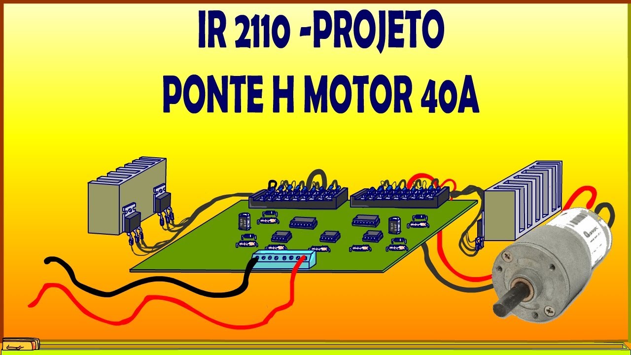


![H Bridge DC Motor Driver/Control Circuit [40A PWM, Power MOSFETs]](https://i.ytimg.com/vi_webp/4cxWFa4kg_o/maxresdefault.webp)


This lecture covers the fundamental motor and encoder systems used in micromouse robots, including the choice of brushed motors over brushless motors for their simplicity and lower cost, the use of H-bridges with transistors and flyback diodes for bidirectional motor control, and the implementation of PWM (Pulse Width Modulation) for precise speed control. The lecture also explains how magnetic encoders with Hall effect sensors measure motor rotation to provide position feedback, enabling closed-loop control where the microcontroller adjusts motor speed based on encoder readings to achieve accurate navigation through mazes.
Micromouse Lecture 2: Motors & Encoders Explained
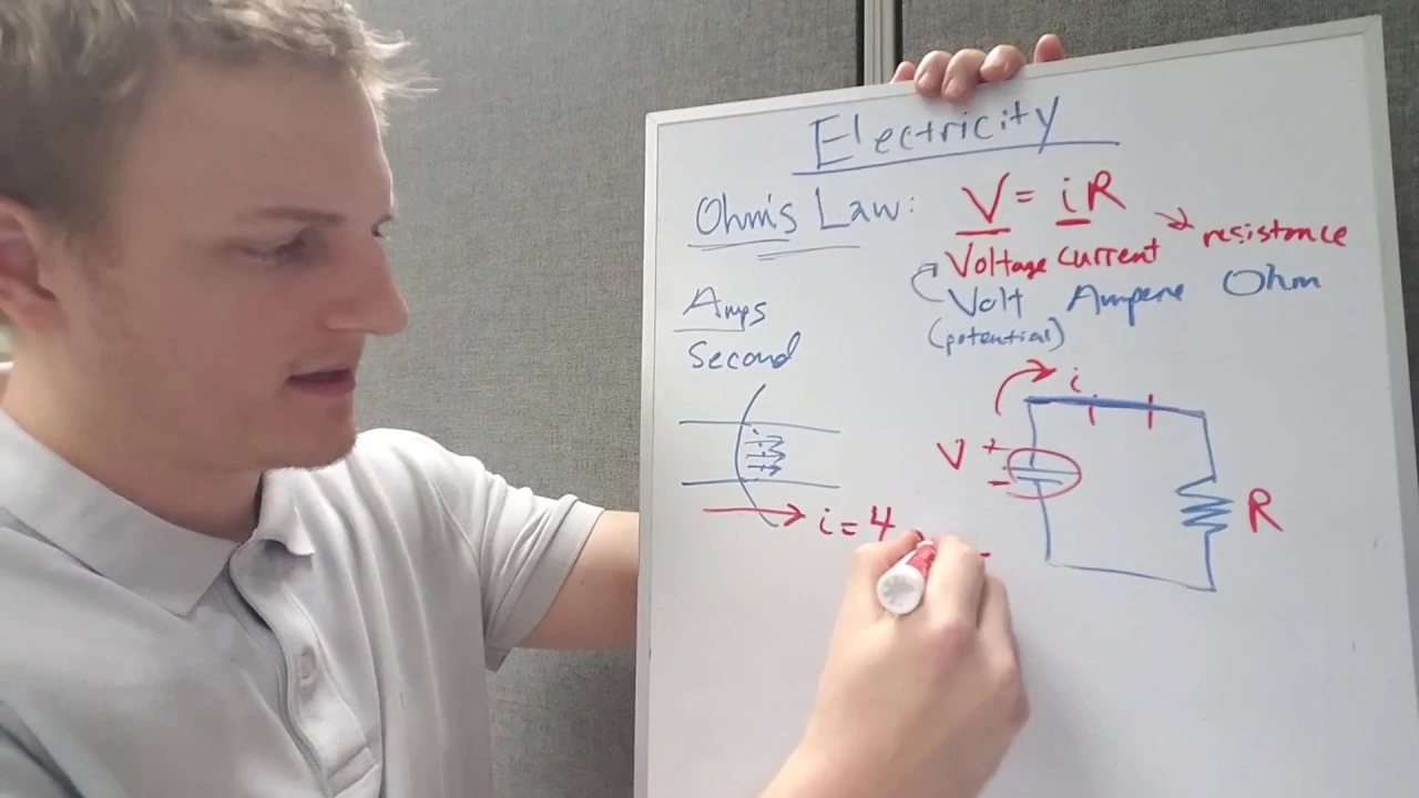
Added:Basic DC circuit theory, including voltage, current, resistance, and Ohm's law.
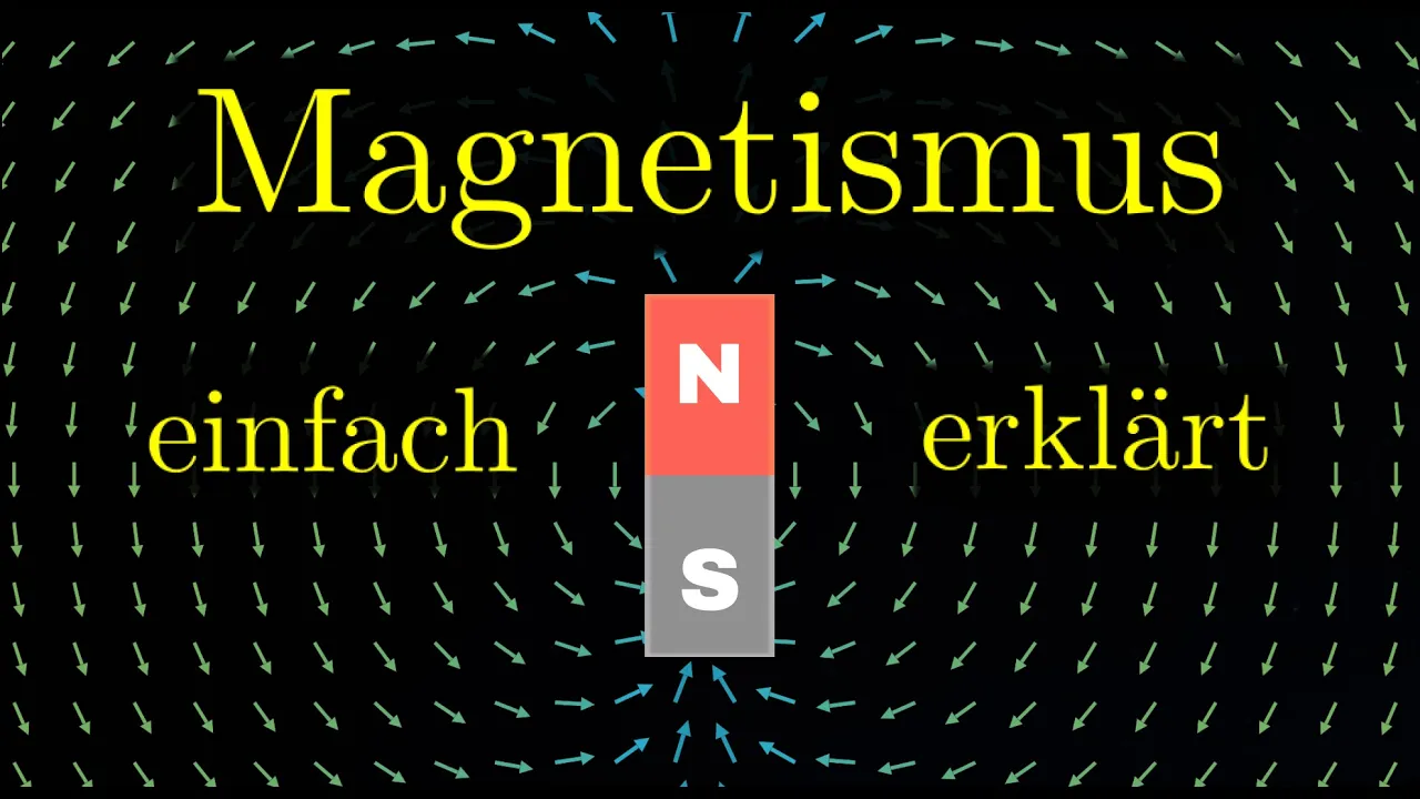
Fundamental concepts of electromagnetism, particularly how magnetic fields interact with electric currents to produce force.
The difference between digital and analog signals, and how microcontrollers read and write basic high/low states.
Introductory programming logic for microcontrollers, such as loops, interrupts, and basic I/O configuration.
Implementation of PID (Proportional-Integral-Derivative) control loops for precise speed and position control of the robot's wheels.
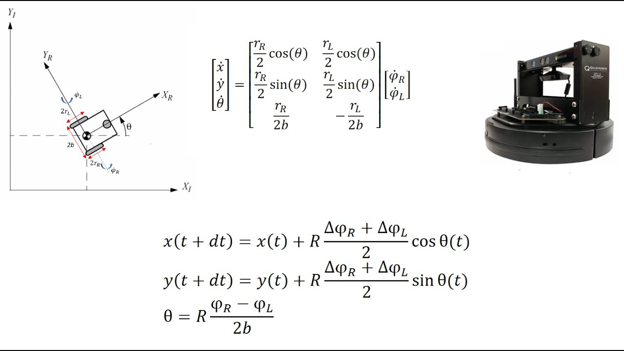
Odometry and dead reckoning, using encoder data to calculate and track the robot's real-time position (X, Y coordinates) in the maze.
Motor driver selection and PCB layout considerations, including thermal management and noise isolation for H-bridge circuits.
Motion profiling techniques, such as trapezoidal or S-curve acceleration, to prevent wheel slip and ensure smooth transitions.
5.5K views112likes41:14Original Release: 2021-10-20
yes [Music] this year so today we're going to be talking about motors and encoders so we're going to go do a quick overview of some types of motors that you could use as well as um which motors we're going to be using for micro mouse we're also going to talk about how to control motors both the direction that they spin and how fast they spin so they're power level and then we're also going to talk about encoders which is actually how we measure how far a motor has spun and we can use this to control our motors precisely so this is just a little sort of visual overview of what we're going to talk about today and how it all fits together we're going to talk about all these things in detail going forward but this is just kind of a little preview so our microcontroller on our rat that's what we're using to control everything uh in particular we send a signal to our motor driver our h-bridge and from that that sends a signal to our motors which our motors turn on then and they'll spin as they spin that spin is measured by our encoders which sends that information back to the microcontroller so as i said we're going to be talking about all these things in details but this is how our sort of motor control system is going to work at a high level all right so now we're going to talk a little bit about the motors that we have on our rat um so first of all i'm going to talk about uh types of motors we have brushed and brushless motors here um so these are the two major like kinds of motors that you would see in a lot of applications nowadays um and the biggest difference as is probably apparent by the naming is one has brushes that actually physically contacts the spinning rotor and the other one doesn't where it just spins in the middle um controlled by three moving uh three sorry static uh electromagnets um so one of the like big uh advantages of these brushless motors is just that they're a lot more efficient because they don't have the friction of those brushes they're more durable because those brushes wear out um and you know they're better for high precision applications uh like because you can measure them a little bit better and have greater control over your motor um the biggest downside of these though is that they're they're pretty expensive um and they're hard to they're hard to control as you can see there's actually three um wires going into this one so they're all special um and they're more effort than these brushed motors that i'm about to talk about um the places where you'd see brushed motors would include like uh you know drones use uh brushless motors sorry i said brushed earlier uh they drones use brushless motors uh you know sometimes vacuums advertise brushless on the side or something you know uh to imply that they're better um and the brushless motors are just you know seen in a wide variety of applications uh and then we have brushed motors for the other type we have here um of course they're much easier to control because as you can see there's only two inputs there these actually just give a dc voltage whereas these brushless motors you have to give three-phase ac but because of that dc input that means that they're super easy to control because you could just give it it goes faster when you when you give more voltage and it goes slower when you give it less voltage simple simple they're also super cheap uh a lot cheaper than these so for those reasons we're using brushed motors for our rat instead of brushless and uh so yeah here's the exact motors that we're gonna be using this is a nice big picture of something that's about this big um but anyways uh so these waters as i said before are brushed uh you don't see them but they are back here instead of this uh uh black plastic cap um they also the big feature is that they have a thirty to one gear ratio does anyone uh in here know like why we'd want that on the front of our motor you can raise your hand or something or shout out you know what's up speed yeah sort of uh so so 30 to one here actually means that for every 30 rotations that our main motor like spins our output is only going to spin one time so that could that would actually decrease our speed but uh one of the things that we get from that because we decrease our speed we actually increase our torque output which basically means that um our rat you know can can go a little slower than these motors because essentially if you like pinch them there's not a lot of torque so they will stop even at full power if you just pinch them so we don't want that we want our rat to be able to you know go over like small bumps in our maze or something so we have a 30-1 gear ratio here to give it a little more torque so that our rat doesn't go infinite speed either because these do spin at like 3000 rpm or actually i don't know the number but they spin pretty quick uh regardless so uh we need the gear ratio there um the gearbox to bring that down to something more usable the other figure here that we have that's really useful is our six volts ideal operating voltage that just tells us that this motor is designed to work at six volts um and below that it'll go slower nominally and above that it'll go faster and if you go too far above then it may burn out our rats as uh you might have seen in lecture one we said that our battery voltage is 7.4 volts um so that's a little bit above what these what these normally use but we're never going to be going full speed and if you are then that's really impressive um anyways so that tells us uh you know that we're matching our battery voltage and our in our motor voltage so that uh everything lines up properly the last important figure here is our max current draw of 0.67 amps that will come in more important later when we talk about motor control and we see that uh in order to control our motor we have to be able to control that much current draw otherwise we'd have uh we'd have our controller burning up before our motor actually maxes out so if it gets stuck then you might burn something rather than it just you know struggling and heating up a little bit but anyways those are the motors that we use on our rat so that's it about for motors does anyone have any questions about that anything we went over all right great motors are pretty easy oh no oh you're good all right also as going forward feel free to uh raise your hand at any point we are here to answer your questions and um it's usually better to clarify something while we're talking about it rather than after uh but yeah we'll have breaking points like this but feel free to raise your hand anytime uh without further ado we're going to talk about motor control so we have motors but how are we going to actually use them um you might think we can hook it up directly to a microcontroller pin but this actually will not work because for one the microcontroller only operates at 3.3 volts and that is not enough we saw on a previous slide that it only work that you need at least six volts for it to work fully the other problem with it is it can't draw enough current from the microcontroller in order to power the motor and also if we were to really hook it up like directly to a pin that's not gonna that's not gonna work because we can't control which direction the motor is going we can't control how fast so we need ways to do that and that's what's going to fall under this concept of motor control so the first thing that we're going to use to enable this is a transistor so the idea here is as we see in this little schematic on the side we want to actually be able to use our battery voltage to power our motor we can't just do it directly or else it'll just be on all the time so we need to use the transistor as a switch so we can basically hook our microcontroller pin to the transistor so the transistor when you apply a voltage to the base that will allow current to flow from the collector to the emitter so that basically acts as a switch so if we turn on b uh current can flow so what this is what our circuit will end up looking like we can depending on whether our pin is on and off that will allow current to flow from the battery to ground so that basically allows us to turn our motor on and off using the battery voltage and not the voltage from the pin so that solves our first problem of having enough voltage but we still have a few issues here so and those issues are going to be resolved using a flyback diode so when we have motors when they're turning they basically have electromagnets in them and that's going to act as a magnet and so you may know that anytime you have a magnetic field that's going to you're going to have some inductance and so when you're turning your motor on and off that can become a problem in fact when you turn your motor off you're going to have a back emf or a temporary voltage spike that could go and fry your transistor so that's not good so what we need is a diode which is going to allow current to flow in one direction and so where we put it is right here so that when we turn our motor off and we get that spike in voltage any current is going to go and flow back up to our batteries as opposed to going down to and down and frying our transistor but since it is a diode it can't flow downwards normally so it's not like we have a short circuit here so that flyback diode is going to allow us to actually use this without those voltage spikes doing damage and now we'll see what happens when we take that system and we just multiply times a bunch so here's essentially what we call an h bridge because it looks kind of like an h here um but essentially it's we take that we have four transistors here and four flyback diodes and um what we see happens here is when we turn on just uh the top and the uh the top left and the bottom right ones who we call them q1 and q4 we see that current flows from the motor to the right side so it's going to flow through um and spin the motor in one direction whereas if we uh take this and we turn on q3 and q2 here we'll see that the path becomes something like this and our motor starts spinning the other direction isn't that fancy um and so so that makes that's why we have an h bridge here so you see this this fancy thing um so that's how we're going to control our motors so that we can go both forward and backward uh no problem um now one thing is here with this h bridge the way this is designed there is one uh problem that you could run into so what would happen if we say turned on q3 and q4 does anyone see what would happen here yeah we're going to have a short right here and our power is going to go straight down from vcc to ground and uh fry something probably your h-bridge it's gonna short through those transistors and cause issues so in our program we have to make sure never to turn on uh these these two or these two at the same time but luckily our hardware makes that pretty easy and actually our code templates will uh ensure that you there's not as much of a risk of doing that but do know that that's a way you can insta-fry your little h-bridge on your rat um so yeah so this is one motor and then the h bridge ics on our rack we actually have two motors right so what we do is something called a dual h bridge it's two of them so now we can control two motors uh here's just a diagram of a larger smdh bridge and uh this one's just a schematic of how you might use that h-bridge um but essentially yeah controls2 motors uh we have four inputs and four outputs and you might ask okay that's weird we saw four transistors on the side wouldn't that be four inputs so we'd have eight right uh but now so actually each input is tied into uh each of these two transistors so um input one will turn on both q1 and q4 so that uh so that you only have to you know control one at a time um now do note this still uh doesn't prevent you from turning on like input one and input two and then still causing a short of through all four um but you know uh yeah and then we also just a note here on our uh h fridge we have enable pins uh in the top left and in the bottom right and uh does essentially just enable or disable this ic this is a feature of our specific h-bridge that we might not be using so we just tie them here to 3.3 volts or high so that our motors are always on and responding to whatever input we give them however like if you wanted to turn yours off then like you're in your mouse pcb or something like have a switch for them you could disable that enable pin and that would turn off your motors and disable the h bridge uh yeah let's see oh the other thing we have here is our decoupling capacitors you might see in the schematic here um essentially what these are for is is like a little low-pass filter to reduce noise on our power lines and that's a good thing because um we are interfacing with the 3v3 and the uh battery voltage just through this one h bridge so what's gonna happen is that uh you know again when we turn the motors on and off it's going to uh you know cause spikes or whatever in the voltage and in order to mitigate that from getting to our controls or microcontroller and this h-bridge and you know our ir sensors and everything uh we put these decoupling capacitors here to prevent that yeah all right uh and here's a couple pictures of what h-bridge ics might look like here's a fantastic 3d model of um your rat that you guys are going to get in your kits uh hopefully very soon and here's just a picture of dominic's actually his uh his breakout pcb that he designed last year and uh implemented on his own breadboard rat um so this one's actually an smd component it has a couple more pins because it's a different model but um he's mounting it on top instead of a through-hole thing um and then the one other notable thing here is that uh the h bridge on our rat is actually socketed so if you do pop it and fry it then um you can replace it which hopefully you guys won't have to do but it is a thing that we have just in case so yeah there they are in the circles cool so we've already talked about using an h-bridge which we can use to turn on our motors and turn them in different directions but we haven't talked about yet is how to make our motors move different speeds so the way we're going to accomplish that is be using by using something called pwm or pulse width modulation so you may have mixed paint in your life if you want but what if you imagine you want gray paint and you have white paint and black paint so are is it possible to make gray of course you have to mix some white and some gray paint that so or some black and some white paint to make a gray paint so that's essentially what we have going on here with sorry all good that's essentially what we have going on here with um pwm so our microcontroller pins can only turn on and off that's our black and white paint but we can create a range of colors or a range of voltages by mixing our on and off signals by turning our pin on and off rapidly to sort of simulate a place in between our maximum and minimum voltage so the duty cycle is the percent of time that we actually are in the on state versus the off state so the higher the duty cycle the higher the perceived voltage will be and our frequency is the amount of changes per second of on and off on and off so that's our cycles so this is actually what our signals will look like in pwm so if you have a 50 duty cycle we're on half the time off half the time and so that'll average out to be like right in the middle like that so that would be running our motors at half speed uh say we wanted to go a little faster and we were on 75 of the time off 25 of the time then it would average out to be something a little bit more like this so our motors are running faster because our my controller pin is on more of the time and then 25 of the time uh there's 25 duty cycle you have similar phenomenon here it's going to be running our motors slowly a little bit slower because uh the motor or because the mic controller is off the pin is off for more of the time that is on but it's still on a little bit so motors and you might think that it's not super good to have it turning on and off all the time right because that could be jerky but as it turns out motors you know they react slowly to these changes because they are physically moving and they also do they also do act as inductors so it is going to end up looking pretty smooth so we don't have to worry about that and so we can use pwm to control motors um okay all right so now we've talked about this but how are we actually gonna do this on the microcontroller so the way we're gonna use it is by using timers which we have on our microcontroller our microcontroller's clock has a speed of 16 megahertz and our h bridge has a max frequency of 5 kilohertz for pwm so by doing a little bit of division that we can actually have our clock cycle be 3200 so that means that in 3200 clock cycles um we can actually have if we're on for 1600 and then off for 1600 that corresponds to a 50 duty cycle um and so 3200 that's essentially our frequency well it's our it's actually our period but um yeah that's that was the example i just gave all right so uh again we'll pause again for questions pretty soon we're gonna talk about encoders but first of all does anyone have any questions about motor control h bridges pwm any of the stuff that we have just discussed or anything else what's that why do we bother with manipulating the speed of the motor if the micromaster's goal is to just like get through the maze is there like a time description as well or uh yeah i mean the the goal of micro mouse uh you'll see in the competitions is to go through the maze uh one to get to the end and then two to do it as fast as possible so the other thing is if we only had the granule control on or off these rats actually moved pretty fast so you'd you'd be like speeding through the maze um and not having you know you'd probably like run into walls because you wouldn't have enough time to like actually stop and skid or whatever um so we we need pwm here in order to smoothly start and stop and move properly um without just you know on or off because frankly they do really go fast so uh yeah any other questions let's see um now we can talk about encoders so as we talked about before um uh yeah encoders are what measure our position of our motors so we can figure out how far we've gone so uh one of the things is they they just measure the rotation of our motor and um they measure like how far a rat can actually travel because if you see uh in our picture there uh you can see that they're actually mounted to the back of the motor so every time the motor does a revolution uh it'll measure that revolution and be like okay we know we've gone this far so our rat knows exactly how far we travel rather than saying oh our motor was on for x time which is not very good because um some of our motors are slightly different so you might go slightly different distances if you turn a motor on uh for a specific specified amount of time rather than going a certain amount of distance um and then the other thing yeah we can we can measure like how fast the rat is actually moving and uh you know counting i didn't read this beforehand it's okay um but yeah so yeah we it simply just uh counts the number of like cycles or like uh divisions that uh we measure um and there's two different kinds of encoders we have magnetic encoders and optical encoders as you can see in those two pictures one of which where you like uh have a wheel that has a photo sensor where the light gets cut on and off so the sensor will essentially count one two three four like uh times when the motor sorry the code wheel goes around and it'll flash on the sensor so you can count that whereas instead with a magnetic disk you're counting how many times does the uh the magnetic field switch sides so yeah let's see magnetic magnetic encoders are the ones that we're going to use these are kind of what are those look like uh yeah so essentially they just sense the change in the position as the motor spins and these magnetic discs here are actually six poles so they have about 60 degrees between each pole as you can see kind of like this and what's up alternating and then they also have two hall effect sensors you can see right here where they're mounted at 90 degrees from each other and that essentially uh yeah so we can measure the uh volt you can measure the um the change in the magnetic field using these hall effect sensors which hall effect is defined here as uh you know the um basically it creates voltage uh when our um magnetic field shifts from side to side um yes 90 degrees okay cool all right so i'm going to talk a little bit more about how magnetic encoders work so we've already established that our magnetic poles are 60 degrees apart and our hall effect sensors are 90 degrees apart so what does this mean this actually means that we have an encoder count every 30 degrees are you convinced i'm not convinced we need to take a look at this um so when i so let's say we start at zero degrees our first sensor sees a north and our second sensor is in between so it doesn't see anything so then if we spin our motor another 30 degrees our first sensor doesn't see anything our second sensor sees a south keeps spinning we see south and nothing then nothing and north and then finally again we see north and nothing so basically we sort of have these four distinct states we all within 120 degrees of rotation um so that means that every 30 degrees we can actually detect a change and so that change is going to be one encoder count so we know we've moved a certain amount and so the same thing applies counterclockwise uh where we see but you'll notice here that the order that we see these patterns of north and south is different so say we start at north then our second sensor is going to see north then our our first sensor is going to see south then our second sensor is going to see south and then finally our first sensor is going to see north again so it's the same patterns but they're in different directions so we can actually tell which direction our motor has spun which is going to be really important because that'll um because knowing which direction our motor is spinning is going to allow us to control it better so not only uh every 30 degrees can we do we know that that's how far it's traveled we also can tell which direction we're going uh so let's take a little bit to think about how precise are encoders so 30 degrees every motor rotation doesn't sound like very much or it sounds doesn't sound very precise but remember we're counting every 30 degrees but that so that means that every in 360 degree rotation we have 12 counts as the motor is spinning uh what's going on here um and so we also have this 31 gear ratio so we multiply that out it means we're actually going to be have 360 counts per wheel rotation and then our wheel dimension is about 3.2 centimeters about 10 centimeters of circumference oh and then we just do a little bit of math and divide the 360 by 10 centimeters basically means that we have 36 counts per centimeter so that's sort of just a little bit of an estimate of how precise encoders are so it means every centimeter our rat travels we can know that there's like we can divide that into 36 little counts so we can actually a 36th of a centimeter we can discern how far that travels of course that's not going to be exact because our motors or our wheels can skid a little bit so it's not 100 precise but that gives us a sense of how useful encoders are going to be because we'll know exactly how far we've traveled all right so tim's going to talk a little bit about how to oh yeah so using encoders with our mcu is uh you know it sounds really complicated but uh because of what you just saw and how they work but really it's it's uh pretty simple because we just use timers yet again um so essentially these timers instead of counting up based on time we use them as counters to keep track of our rotation and there's something really cool we uh use our hall effect sensors and we put them into our pins and we get two timer channels and then what happens is we use encoder mode on those two timer channels and that was essentially interpret the signal for us so we so that the microcontroller does all the work um we don't have to you know figure out the this one went north south or whatever like um the encoder mode is made for these things because they know that a ton of people use them so it interprets the signals for us and gives us a nice uh oh positive encoder counts when we go forward negative when we go backwards um so that's super easy to use and then uh let's go back to this overview um to you know see exactly what we were doing so as we saw before we from our microcontroller it sends a pwm signal to our h-bridge motor driver here and then that turns the motors on and off uh like a million times per second or um at a certain duty cycle in order to activate our motors and give it an average voltage that is uh proportional to how fast the motors are spinning so based on that speed uh our motors are going to turn and that's going to cause feedback in the encoders it's going to measure the magnetic field changing on those disks and create pulses that our microcontroller reads back and that way we get feedback based on our uh output which is super important for later um but for now that's about it for today because i know that's a lot of information pretty dense but does anyone have any questions over anything that we went over we'll go over a little bit of logistical stuff in like three seconds so questions about that can stay but anything about the uh subject matter at hand great yeah what's up general question about those the uh discs are like um they're permanent magnets so the hall effect sensors i don't know exactly how they work but essentially they just create a pulse um given 3.3 volts they just give a one or a zero based on um where on on which direction the uh uh magnetic field is pointing and actually if you look uh let's i don't know i can't go back can you go back yeah yeah um back to where it was yeah uh something like this you can see that the uh hall of fame sensors are aligned like right uh they're they're aligned very specifically so that um it lines up with how they um how they respond so these are just permanent magnets waving over the sensors and that is enough to give us a feedback signal okay cool any other questions does that make sense cool would like that light encoder it's possible that these magnets may lose their magnetism there are permanent magnets and uh i don't know the specifics of of like the magnetism but since they're permanent magnets they're you know good and they're they get jostled around they're gonna keep their magnetism um and they're not like waving by any other magnets either so there's no reason they would lose their magnetism so these are pretty accurate the light sensors are a lot harder to implement and uh and you know you need a lot more complex electronics to do that um so that's why we use the magnetic ones yeah so there are some advantages and disadvantages to magnetic versus optical encoders but one thing is uh so it's interesting that you brought up the effect with magnetic encoders but it's actually you're more likely to have interference with optical encoders because you it has to actually travel through the air you've got light through the air so if that gets messed up or if there's like particles in the air you can have some problems there whereas magnets like our hall effect sensors are always going to change to detect changes in magnetic field so unless you're like running this in a very weird magnetic environment uh magnetic sensors are gonna be yeah our yeah our magnetic hall effect sensors are gonna do just fine for our purposes okay those are those like colors uh soldered onto the motors yeah they are um yeah we we soldered them on for you guys because they're designed pretty poorly uh so they're like pretty tricky to solder um so we'll get them to you with the encoders on them already yeah all right cool speaking of soldering shall we talk about some logistical things eventually when you click all the way through there we go assignment 2.1 i know no one has started assignment 1.1 yet because actually i haven't looked but you guys can't couldn't have finished it by now but uh we'll talk more about assignment 1.1 in a second sorry um you guys don't worry you guys have time you guys got time i know we said the due date was friday it's actually next friday talk about that in a second um but anyways assignment 2.1 so we're going to be uh soldering our motor control circuit so everything that you just saw in our uh diagrams and everything you're going to be soldering on your wrap and then that will be making your oh yeah you're going to make the schematic that goes along with that so something similar to the schematic that you saw here you're going to implement it all and then you're going to write some code to make your motors and encoders work and wow your uh rats going to get to move for the first time i know you guys haven't even seen your rats yet you'll get them soon um but this will be due a week like two weeks away which should be plenty of time um yeah so that's all for assignment 2.1 and i know you guys want to mention though yeah we do it's just later anyway a couple things some of you guys haven't done your safety and you haven't done your deposit and you haven't done your piazza please do it um it's not that many of you but you know who you are um yeah anyway just if you need help let me know yeah deadline for those is it's gonna be friday this friday midnight if you don't do it by then uh like we've already sent you guys emails and everything if you haven't done like the safety stuff yet so this friday midnight hard deadline if you don't do safety deposit and piazza you guys are getting dropped so yeah but hopefully all you guys have done that which a lot of you have so you're good um and then next on the list we have our work session so we know that there's been some uh we haven't like gotten you guys kits yet and there's been a little uncertainty without this all working but we're gonna have a work session on sunday afternoon so you guys can come into the lab ask for help uh get yeah just or just have some dedicated work time if you don't have to have specific questions just come into the lab get a little bit of work on micromost done and get that you can either work on finishing up assignment 1.1 you can also work on assignment 2.1 if you are ahead of schedule um so yeah go ahead and come in and in addition to this feel free to come in during our lab hours we had lab hours today um and there were some people that came in to ask questions that was really helpful we have some more lab hours this week as well as you can come in really to the lab anytime uh because we're here in the lab even when we don't have official lab hours sometimes as well as other officers so please come in and ask for help if you if you have questions or just uh come and work and you'll need to do that when you have soldering you guys know how to get to the lab right we're good raise your hand if you don't know how to get the lab you've never been there never been there all right well actually at the end of this we'll walk you to the lab because we'll show you where your kids are we'll show you yeah um yeah and then another thing soldering workshop they've been moving around dates have been hard because we're in person again and everyone forgets that people have things and things to do and places to be um so yes it's moved uh to this thursday right that is this thursday or is it next thursday that's next thursday that is next thursday not this thursday it was this thursday now it is going to be next thursday from 6 30 to 8 30 pm fall to your second floor what's up calendar no it's not they don't know what they're doing it was going to be the 27th it is the 28th i think i asked literally this morning so yeah sorry about the confusion with the soldering workshop for those of you that don't have soldering experience though and don't and i don't wouldn't probably not recommend you wait until going to this um come to the work session to get help with soldering go ahead and come to lab hours we're here to help you um so we don't want that to be a problem and we'll be lenient with the with the assignment as needed uh based on that because we know that this has kind of been a little bit confusing with all these dates changing and stuff yeah so um as for soldering know that any time you guys go into the lab it's open from what 10 to 6 p.m 10 a.m to 6 p.m you can come in uh there will be an officer in there so if the only thing you got to get done is the soldering part they will know how to teach you how to solder at least they better so they will um so if that's what's uh stopping you from finishing this assignment uh don't hesitate to you know come in during lab hours and get some help yeah and then next thing yes as i said before assignment 1.1 is due next friday not this friday thankfully because we haven't gotten your kits yet speaking of kits um we had some trouble with some parts we're going to do some hacky stuff to get them to you um that will be done hopefully by tomorrow so you guys should be able to come in once you've done your safety deposit and joining the piazza you will be able to come in and get your kits and we'll check you off you guys have to have your entire team has to be not there but your entire team has to be checked off for all those three um let me know if you haven't talked to your team members yet because i know we haven't had a social for that that's in the works um anyways yes so we'll get those to you uh either you know in the next couple days or if you can't get it by then uh like we'll have our lab hours then you'll just have to speed solder um i i think it's fine people can come in and use the kits there's just one part missing from the kits that you are going to need from the for the soldering assignment so that won't be there yet it's the headers if you i don't know if you guys have read through the assignment yet but uh the headers are not ready everything else is ready so you can solder everything else um or you can wait until the headers are there they'll be there very soon um we're working on it yeah okay uh does anyone have any questions about assignment 1.1 yeah what's up um um i'm planning to be in the lab from one to five um but i'll send i'll confirm that um soon yeah um oh speaking of assignment 1.1 um has anyone had any troubles getting eagle to work properly because i don't know how many people have like started the software portion but we know that autodesk has been really weird with their software like starting in august so we haven't like looked through it ourselves and been 100 certain what is going on because it's really confusing with how eagle how to get eagle um if you guys if you guys have successfully gotten eagle to work please let me know because i still have no idea how that's how that's working it's completely different than in previous years and i already have an account so they won't let me make a new one um question all right uh i have no idea how yahtzo works so what is that this for because i haven't encountered i joined the class but i don't know what just a yeah so we're going to be sending out announcements on piazza uh we'll send them out on discord as well but sometimes they'll be more long in detail that's also why we'll be posting all of our assignments and and our lectures and our recordings and everything kind of a bunch of resources you can also ask questions there it's a great place to ask questions because it kind of keeps everything all in one place and students can even respond to each other or we will respond to those so you guys will use piazza in the future for some other classes where uh we we do use it a lot here at ucla so yeah okay any other questions about assignment 1.1 or 2.1 or logistics yeah what's up we are the lab hours like micro non-specific or like do i just go to any level you can go to any lab hour you want but dominic and i will only be there in the lab hours that are listed on the website and on piazza under the staff tab there are like the resources and stuff there will be information on where our lab hours are it's also in the syllabus uh we i think it's uh tuesday from 12 p.m to 4 p.m is the major micro mass block um but i'm also there on thursdays and i'm there a lot of time anyways um but if you just need general help like not like even if you need like help with eagle i'm sure there's there will be someone in there that will be able to help you so it's worth coming in if you have like some spare time and want to figure stuff out there will be officers there to help yeah yeah the lab is up in ten to six every day um go on the ieee website has like a list of which offices will be there um but again we're there often other times too even if it's not listed okay and then the very last one last announcement for you i know we're boring you guys all with this logistical crap um but lecture three pid control fancy will be next week not next week in two weeks you guys have i don't know how much this is this is week six right right now it's week four the lecture is week six you guys have the week off next week then but yeah but you have next tuesday off but then the tuesday after that we've got our third lecture on pid control um we'll send the location out asap but similar situation to this yep still tbd on the location but that's when the time is so we're good all right that's about it thank you guys for uh sitting through that and if you haven't been to the lab yet we'll we're going to be going out to the lab after this and we'll be showing where the kids are if you want to see that if you want to see that and if you have any questions feel free to ask yep as always
Up Next
36:31
Micromouse Lecture 1: Power Delivery & Voltage Regulators
@UCLAIEEE
2.7K views•2023-10-24

58:25
MathWorks Virtual RoboSub Simulation Environment | Webinar 2026
@RoboNationInc
209 views•2026-03-10
37:58
Micromouse PID Control: Lecture 3 Tutorial for Maze Navigation
@UCLAIEEE
1.3K views•2023-11-12

25:22
Micromouse: The Fastest Maze-Solving Robots on Earth
@veritasium
23.5M views•2023-05-24
Related Study Plans & Knowledge Roadmaps
Structured learning paths in Robotics
robotics
Building Delta Robots: Kinematics & Pico
01Foundations of Delta Robots & Mechanical Design
02Electronics and Microcontroller Setup with Pi Pico
03Delta Robot Kinematics and Coordinate Math
+ 3 more learning modules
65h6 modules
Explore Roadmap
robotics
Building Ballbots: Dynamics, Kalman & LQR
01Embedded Electronics & Omniwheel Actuation
02Ballbot Kinematics & Rigid Body Dynamics
03IMU Sensors & Kalman Filter State Estimation
+ 2 more learning modules
42h5 modules
Explore Roadmap
robotics
Micromouse: Hardware, PID Control & Flood-Fill
01Electronics & Teensy Microcontroller Basics
02Sensors and Actuators: Motors, Encoders & IR
03Precision Movement: Implementing PID Control
+ 2 more learning modules
35h5 modules
Explore Roadmap
robotics
CDPR: Kinematics, Arduino & Winch Control
01Foundations of Arduino & Basic Electronics
02Stepper Motors and Winch Mechanics
03Kinematics of 2D Cable-Driven Robots
+ 2 more learning modules
28h5 modules
Explore Roadmap