Building Delta Robots: Kinematics & Pico
Learning Goal: Design, fabricate, and program a high-speed 3-DOF Delta robot for pick-and-place, implementing parallel manipulator kinematic equations, closed-loop stepper control, and G-code trajectory planning on a Raspberry Pi Pico.
Prerequisites
- Mathematics: High school trigonometry, vector geometry, and basic matrix transformation theory.
- Programming: Fundamental C/C++ knowledge (pointers, structures, and basic object-oriented concepts). No MicroPython is used due to critical real-time execution constraints.
- Electronics: Basic understanding of DC power delivery, stepper motors, and microcontroller interfaces (SPI, I2C, GPIO).
Estimated Study Time
- Total Study Time: 65 Hours (including CAD design, hardware fabrication, mathematical derivations, C++ firmware development, and physical tuning).
Module 1: Fundamentals of Delta Robots & Mechanical Design
This module introduces parallel manipulator design theory, comparing parallel architectures to traditional serial industrial arms. You will learn about the structural anatomy of a 3-DOF Delta robot—focusing on fixed upper platforms, passive parallelograms, and traveling end-effector platforms. In addition, this module details the fabrication and assembly of highly precise, low-backlash joint mechanisms such as magnetic ball joints.
Recommended Videos
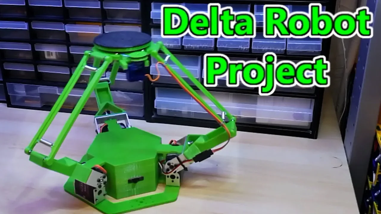
- Why this video: This video offers an excellent physical teardown of a desktop 3-DOF delta robot. It demonstrates how standard 3D-printed brackets, parallel carbon fiber rods, and universal joints are arranged to preserve parallel orientation of the end-effector.
- Knowledge Checkpoint:
- Identify the function of the parallel linkage structure (parallelograms) in constraining end-effector rotation.
- Describe how to choose rod lengths to maximize the vertical and radial workspace.
- Explain the benefit of placing the heavy actuator motors on the fixed base instead of the moving arms.
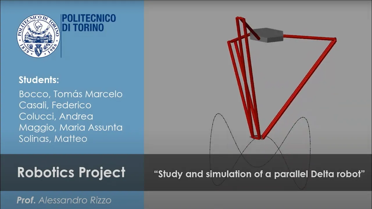
- Why this video: This video provides a simulation demonstrating structural limits, geometric constraints, and multi-body interactions of a parallel delta arm. It highlights the relationships between the fixed platform, upper active arms, and lower passive arms.
- Knowledge Checkpoint:
- Define the geometric parameters (base radius, upper arm length, lower parallelogram length, and platform radius) needed for kinematic model configuration.
- Identify the singular points in a Delta robot's workspace where the arm structure can lock or collapse.
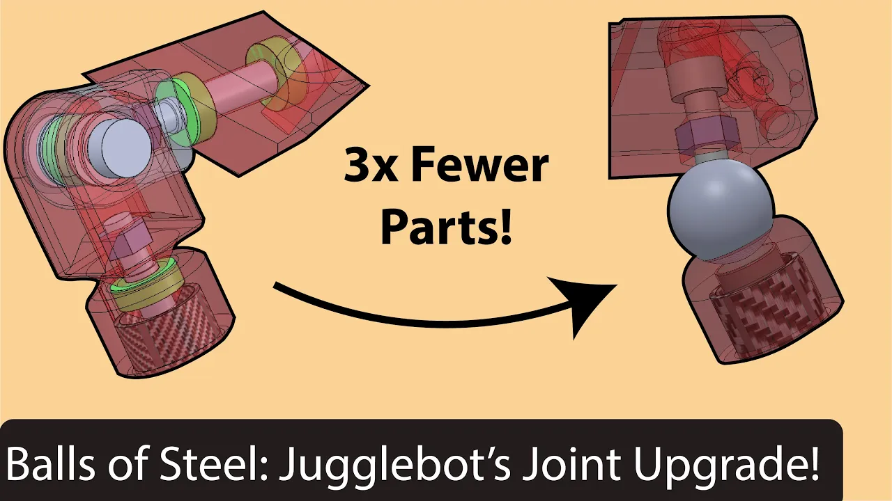
- Why this video: Backlash is the primary enemy of delta robot precision. This video breaks down a practical mechanical design for magnetic ball-and-socket joints, detailing the assembly components (threaded metal balls, neodymium magnets, and low-friction housings) that keep parallel arms locked without mechanical play.
- Knowledge Checkpoint:
- Sketch the assembly stack-up of a high-performance magnetic joint.
- Explain the trade-offs of magnetic joints regarding holding force vs. maximum angular deviation before joint separation.
💡 Independent Research Task: The video pool lacks a complete visual CAD design tutorial for a delta robot base. We highly recommend searching YouTube for "Fusion 360 delta robot design tutorial" to practice sketching the base platform layout with 120-degree symmetry.
Module 2: Electronics and Microcontroller Setup with Pi Pico
Real-time, high-speed step generation requires a powerful controller and efficient low-level code. In this module, you will set up the Raspberry Pi Pico using the official C/C++ SDK. We will cover the configuration of step/direction stepper drivers (such as the TMC2209), coordinate real-time step execution on a dual-core ARM Cortex-M0+ microcontroller, and explore the use of the hardware Programmable I/O (PIO) state machines.
Recommended Videos

- Why this video: This lecture teaches you how to program the Raspberry Pi Pico using bare-metal C++ rather than high-overhead MicroPython. It explains the toolchain setup, CMake building processes, and direct register access required for fast hardware execution.
- Knowledge Checkpoint:
- Install the ARM GCC toolchain and compile a basic C++ script using CMake.
- Describe the memory architecture of the RP2040 chip (SRAM allocation and flash speed).
- Set up hardware timers in C++ to generate high-frequency periodic interrupts.

- Why this video: Generating stepper pulses at high speeds cannot be interrupted by background routines like G-code parsing. This video covers the RP2040 dual-core architecture, explaining how to run trajectory calculation on Core 0 while executing real-time stepper control on Core 1.
- Knowledge Checkpoint:
- Initialize the second core in C++ using
multicore_launch_core1(). - Implement thread-safe communication between Core 0 and Core 1 using hardware FIFO queues (
multicore_fifo_push_blockingandmulticore_fifo_pop_blocking). - Protect shared variables using mutexes to avoid race conditions.
- Initialize the second core in C++ using

- Why this video: This video demonstrates how to use the Pico's custom hardware block, the PIO (Programmable Input/Output), to drive stepper motors. The PIO can output precise pulse frequencies without consuming main CPU cycles, which prevents step jitter at high speeds.
- Knowledge Checkpoint:
- Write a basic PIO assembly program to pulse a step pin based on data pushed to its transmit FIFO.
- Wire a Pico GPIO pin to a step/direction stepper driver and configure microstepping modes.
Module 3: Delta Robot Kinematics and Coordinate Math
To control a parallel robot, we must convert target linear coordinates of the end-effector into the joint angles of the active stepper motors. This module covers the geometric derivations for inverse kinematics (IK) and forward kinematics (FK) of parallel manipulators, along with their implementation in C++ class functions.
Recommended Videos

- Why this video: This video visualizes vector loop equations for parallel robots. It breaks down the system by analyzing each parallel leg as an individual chain to solve the coordinates of the platform attachment points.
- Knowledge Checkpoint:
- Write the vector loop equation for one arm of a Delta robot: .
- Isolate individual arm planar coordinates using trigonometry to calculate the required angular rotation () for a given end-effector coordinates .

- Why this video: This video covers the practical translation of coordinate system diagrams and geometric offsets directly into clean embedded software. It explains step-by-step how to map raw physical constraints to code variables.
- Knowledge Checkpoint:
- Set up structural constants (link lengths, joint offsets, radial sizes) in code.
- Implement trigonometric functions (
atan2,acos,sqrt) efficiently within a high-frequency loops on a microcontroller.
⚠️ Video Pool Limitation Note: The video pool does not contain a step-by-step mathematical proof specifically solving the intersection of three spheres for Delta Forward Kinematics. To master this, research the mathematical paper "A Simple and General Closed-Form Method for the Forward Kinematics of Delta Robots" online.
Module 4: Trajectory Planning and G-code Parsing
🔄 Curriculum Correction: Trajectory planning is placed before closed-loop control. Tuning PID feedback or closed-loop error-correction is highly impractical without smooth, deterministic open-loop trajectories to act as our baseline command signals.
High-speed delta pick-and-place requires continuous, smooth motion to avoid mechanical shaking and structural vibrations. This module covers how to write a simple G-code parser to parse coordinate movements, and how to implement trapezoidal and S-curve trajectory profiling to control acceleration and deceleration.
Recommended Videos

- Why this video: This lecture compares trapezoidal velocity profiles with S-curve (7-segment) velocity profiles. It mathematically explains why step changes in acceleration (infinite jerk) cause mechanical vibration, and how the S-curve resolves this issue.
- Knowledge Checkpoint:
- Contrast trapezoidal acceleration with S-curve (7-segment) linear jerk profile transitions.
- Define the 7 distinct phases of a complete S-curve motion profile: constant jerk acceleration, constant acceleration, decreasing jerk acceleration, constant velocity, and their deceleration equivalents.
- Calculate intermediate positional setpoints over time given boundaries for , , and .

- Why this video: Translating S-curve mathematics to code can be challenging. This video explains how to handle edge cases, such as when target travel distances are too short to reach maximum velocity or acceleration limits.
- Knowledge Checkpoint:
- Write code logic that handles short-move trajectory generation where the constant-velocity phase is bypassed.
- Implement conditional execution branches to determine which phase of an S-curve profile is active at any given millisecond.

- Why this video: This video demonstrates real-time tracking performance of embedded S-curves. It shows how configuring target parameter limits prevents actuator satruation during fast direction changes.
- Knowledge Checkpoint:
- Explain how to set step generation frequency dynamically on a microcontroller based on an active trajectory profile.
- Design a multi-axis sync algorithm to ensure all three motor arms start and stop their movements at the exact same moment.
Module 5: Closed-Loop Stepper Control & PID Feedback
This module covers upgrading standard open-loop stepper motors into high-speed closed-loop servos. You will learn how to interface magnetic rotary encoders, compute real-time angular position errors, and implement a high-frequency PID controller on the Pi Pico to eliminate step loss and correct mechanical deviation.
Recommended Videos
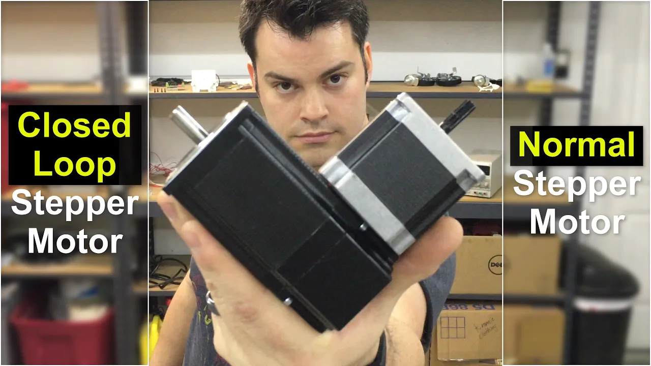
- Why this video: This video explains how open-loop steppers lose sync when load limits are exceeded, and how closed-loop feedback solves this issue. It details how checking the physical motor angle using encoder feedback allows the system to adjust current levels on the fly.
- Knowledge Checkpoint:
- Explain step-loss and describe the conditions under which a stepper motor stalls in an open-loop configuration.
- Describe how real-time current scaling based on angular error reduces motor operating temperatures and increases efficiency.
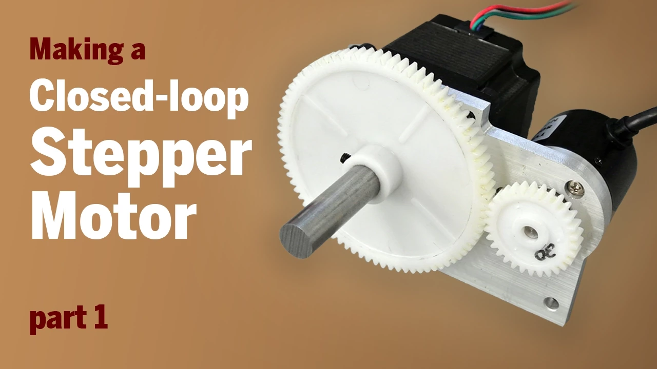
- Why this video: This video demonstrates the step-by-step mechanical installation of a custom encoder disc and PCB to the rear shaft of a standard stepper motor, explaining how to convert a standard motor into a closed-loop system.
- Knowledge Checkpoint:
- Detail how to mechanically align an encoder magnet or optical disc concentric to the stepper's shaft.
- Compare the advantages and disadvantages of optical quadrature encoders versus absolute magnetic encoders (like the AS5600 or AS5047).
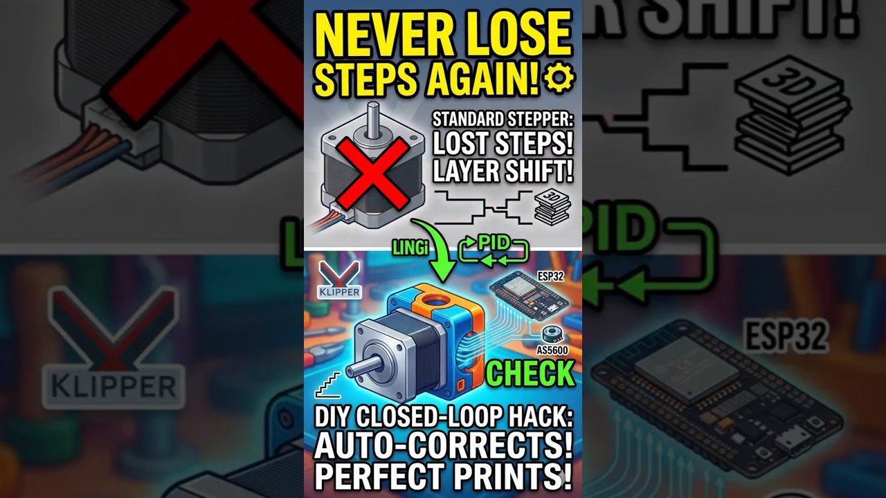
- Why this video: This short video shows a real-world implementation of an AS5600 magnetic encoder paired with high-frequency feedback control. It demonstrates how closed-loop control can actively push back against external mechanical interference.
- Knowledge Checkpoint:
- Write a discrete PID controller algorithm in C++: .
- Configure encoder polling frequency over SPI or I2C to match or exceed a 1 kHz update rate.
- Implement an auto-shutdown safety feature that triggers if the position error remains too high for too long.
Module 6: Assembly, Calibration, and Pick-and-Place Testing
This module brings together physical assembly, microcontroller hardware, kinematics math, trajectory generation, and closed-loop feedback control. You will learn how to configure limit switches for homing, calibrate spatial offsets to ensure physical accuracy, and program high-speed pick-and-place routines.
Recommended Videos
- Why this video: This lecture covers the final assembly, structural configuration, and operational parameters of delta robots. It explains payload limits, homing alignments, and path testing procedures for industrial-style setups.
- Knowledge Checkpoint:
- Configure and wire microswitches or optical endstops to establish home-position references.
- Calibrate joint angle offsets relative to home stops to ensure coordinate frame accuracy.
- Design a simple pick-and-place loop that coordinates vacuum or gripper actuators at the travel ends.

- Why this video: This video showcases a high-speed delta robot executing quick pick-and-place tasks with coordinated multi-axis control. It demonstrates how minimizing path delays yields high throughput in industrial environments.
- Knowledge Checkpoint:
- Explain how to optimize trajectory transit points to smooth transition steps between picking and placing planes.
- Measure and calculate system throughput in Cycles Per Minute (CPM).
Course Map
Below is the dependency map and recommended learning sequence for this curriculum. Note how Module 4 (Trajectory Planning) has been moved before Module 5 (Closed-Loop Control) to ensure you have structured trajectories configured before tuning feedback loops.
Key People Index
- Kris Temmerman (@KrisTemmermanNP): Mechanical engineer and developer who created accessible custom open-hardware designs for adding magnetic and optical closed-loop encoders to standard NEMA stepper motors.
- Leonard Hall (ArduPilot Lead Kinematician): Known for S-Curve trajectory optimization algorithms. His research on minimizing jerk profiles is widely used in high-speed vehicle navigation and industrial multi-axis robotics.
- Isaac879 (@isaac879): Designer and robotics builder who developed and open-sourced clean desktop 3-DOF Delta robot assemblies, demonstrating how 3D-printed joints and standard parallel rods can achieve high accuracy.
Final Self-Assessment
To verify your mastery of the topics covered in this curriculum, complete the following projects and confirm each step:
- Fabrication: Assemble a 3-DOF Delta structure using low-friction joints (such as magnetic ball-and-socket links) with no visible mechanical backlash when manual force is applied to the end-effector.
- Pico SDK Toolchain: Compile and run a C++ script on the Raspberry Pi Pico without using Arduino libraries or MicroPython wrappers.
- Dual-Core Execution: Run a multi-threaded C++ setup where Core 0 parses incoming coordinates while Core 1 executes real-time stepper pulse calculations.
- Kinematics Math: Develop a C++ class that accepts an point and returns three valid motor angles using inverse kinematic equations in under 100 microseconds.
- S-Curve Profile: Write a profile generator that calculates position steps using bounded acceleration and jerk limits, avoiding abrupt motor velocity changes.
- G-code Parsing: Parse standard linear motion blocks (such as
G1 X10 Y-10 Z-150 F500) over USB Serial, converting coordinates to synchronized step pulses. - Closed-Loop Encoder Interface: Read position feedback from a rotary encoder on each arm at a frequency of at least 1 kHz.
- PID Calibration: Tune proportional (), integral (), and derivative () parameters so the motor arms quickly correct external deflection without oscillating.
- Homing Calibration: Execute a homing routine using microswitches to establish a repeatable zero coordinate space accurate to within .
- Pick-and-Place Cycle: Run an automated pick-and-place routine continuously for 10 minutes at high speeds, verifying that the system does not lose sync or drop parts.