









![LAZO ABIERTO y LAZO CERRADO ✅ [Sistemas de CONTROL] #009](https://i.ytimg.com/vi_webp/CxGFoeJ7SD8/maxresdefault.webp)






![Эти механизмы становятся короче, если их растянуть [Veritasium]](https://i.ytimg.com/vi_webp/8BxwcWYlabk/maxresdefault.webp)





SOLO's embedded motion profile engine generates smooth velocity and position profiles using S-curve technology, which creates continuous jerk profiles for smoother mechanical motion compared to conventional PVT methods; unlike traditional approaches that require sending hundreds or thousands of trajectory points from the host computer to the servo drive, this embedded solution only needs a single target reference point, generates all intermediate points locally at 2,000 Hz (up to 10,000 Hz), eliminates interpolation errors, reduces data line traffic, and simplifies integration with minimal programming requirements.
Embedded Motion Profile Engine with St-Curve Control
Added:Fundamentals of kinematics: Understanding the mathematical relationships between position, velocity, acceleration, and jerk (the rate of change of acceleration).
Basic motion profiling: Familiarity with traditional trapezoidal velocity profiles and how they dictate motor acceleration and deceleration transitions.
Conventional PVT (Position, Velocity, Time) control: Understanding how traditional trajectory generation and interpolation methods work in motion controllers.
Closed-loop control systems: Knowledge of proportional-integral-derivative (PID) control loops and how they manage error in position and velocity tracking.
Advanced multi-axis path planning: Exploring how S-curve and St-curve profiles are integrated into multi-axis robotic arms and CNC coordination systems.
Hardware-specific implementation: Learning how to configure, program, and tune the embedded parameters of motor drivers (such as the SOLO controller) to execute these profiles.
Vibration and mechanical resonance mitigation: Analyzing how smooth trajectory profiles minimize physical wear, reduce overshoot, and eliminate high-frequency resonances in mechanical systems.
Dynamic profiling optimization: Studying the trade-offs between jerk limits, cycle times, and motor thermal limits to maximize system throughput.
1.7K views18likes17:02Original Release: 2022-12-29
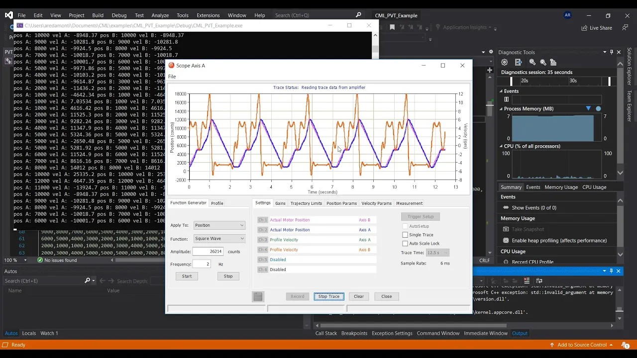
hello today I'm gonna talk about the solos embedded velocity and position profile in G this is actually one of our latest features that we've added into our firmware and I'm gonna show you how it works what are the differences between disk control method technology and conventional methods in the market and how you can actually take advantage out of it for various types of applications especially position and velocity controlling applications so basically the engine that I'm talking about is built on top of the technology which is called SD curve technology we offer both time based and time optimal version of that for position and also for velocity controlling applications later now I'm going to go deeper into the details but for now let's talk a little bit about how actually position or speed controlling is done in a commercial server drives be the method that is called pvt standing for position velocity and time so in a conventional server drive you have actually the user on the let's say the most exterior side of this diagram you have a host computer or a host PC or a embedded system that is uh communicating through a data line which is shown here to a Servo Drive on the Haas side you have this uh engine that computes all the points for the server Drive to follow to have a certain trajectory which we call it pvt encoder so in this pivot encoder you have to actually provide the the algorithm that you want to create a trajectory view which you kind of different namings like trapezoidal which is the simplest one test care of a sticker and other types like minimum trajectories and once you've done that part you need to send all the points to the server drive one by one and the server drive has a unit inside which is called pvt decoder or maybe other names that basically interpolates between all these points that you send from the horse to the server drive through a function that is shown here it's a basically a mathematical function of order three or four that connects these points together so you can see in this image for instance we show uh with dots all the points that the host computer is sending and interpolated does it result inside the Servo drive so basically if you want to go to from point zero to any point that is shown here you need to create all these dot points in the host computer and you need to send them with an orderly passion and in a Time deterministic passion to the server drive so you can interpolate in between these two and it can create the let's say the smooth position provide tracking for your velocity profile tracking there are problems with this uh algorithm the first problem is that as you can see here for every trajectory from the beginning till the end the host computer has to keep sending all these points and literally for a practical application these points are from hundreds of points to thousands of points per second so basically you are gonna occupy the data line that is shown here especially if it's shared between various overdrives a lot during this operation the other problem is for those who are not experiencing these kind of applications will be the programming of this part the PVD encoder so this part is a heavily mathematical part that you have to compute all those points beside all the math involved you need to send them completely in a right time in the right moment and handling these kind of applications in environments like Windows environment Linux environment will be difficult because time is very critical between sending the points and let's say providing all the points for the server Drive thus for uh making such an application you need to write an extensive program covering all the aspects of the asynchronous communications and all of that that is pretty much difficult for those especially those that are not experiencing these kind of things and the other problem with these methods is that in the Servo drive at the end of the day you need to interpolate between these two points so every two point that is provided by the encoder or at the hot side will be interpolated in between because for example the Servo Drive works at 2 000 Hertz per second the position controlling Loop and the horse is working let's say by 100 Hertz so between each point you need to interpolate every time that you run the position controlling certain amount of points and all of them are approximated points they are not accurate or precise points and they're all uh computed based on these uh equation that you can see here so for some server drive this is a order three equation for the rest is Fourth of fifth order but at the end of the day it's all about interpolation which is uh providing you non-accurate points so before talking about the technology of solar I also need to elaborate a bit more about this notion of SD curve motion profile technology and what is it so basically uh here I'm gonna show you uh let's say the notion of the sticker for a position controlling applications the same applies for velocity controlling so here basically as you can see here in this position uh let's say diagram here as shown uh in in any application that you want to go from a point to the other point which are shown here with point zero and the point p as a Target position you want your server drive or your let's say position controller to behave in a way that you don't have a lot of jerky motion or let's say radical reaction to the user input and in order to have that you need to kind of behave the controller so for that purpose to have a let's say a position profile trajectory like this one that you can see here with a very soft take off and soft Landing you need to take care of a lot of things for instance with SD curve technology which provides you all of that not only you can have a very smooth uh position profile between two points you can have very smooth active velocity profile at the same time you can have a very smooth acceleration profile and most importantly you will have a continuous and smooth jerk profile which is actually what you're gonna see in your mechanical system has some sort of vibrations or maybe irrational behavior during the motion so the more and the better you can control the jerk the higher quality will be your motion so before everything I I'd rather to explain a bit about the basic architecture of a motor controller and so I can explain you later how this motion profile in June is kind of combined into this and how it actually works in conjunction with all the rest of the components in this system so here is a bit of a scary looking diagram that you can see here but the water is pretty much a very simple diagram so here is the diagram of a controlling of a let's say uh a brushless or a three-phase model under filtering the control you can see here at the at the very right side I have the motor and all the rest of this diagram is actually inside the servo driver inside the motor controller most of these blocks right now for us are not important the only part that we are interested in is this side of the story which are the controllers so basically infiltrated control would be at least are having four different type controllers we have the torque controller and the direct current controller we have a speed controller and position control and for our purpose today our focus is going to be only on the top side of this diagram which is the torque controller the speed control and position controller you can see in this diagram we have torque controller very close to the motor so providing and controlling the torque of the motor in the fastest possible way and with the highest let's say update rate then we have a speed controller and position controller the other side that are taking care of the Velocity control if you need to control the velocity or if you're controlling the position taking care of the position controlling speed controlling and torque controlling at the same time so basically if you use torque control you only are using this Loop this two controller and this one here the Dual current controller if you are using speed controller you're using a speed control API torque controller and direct current controller and of course if you're using position controller it will be cascaded into this diagram so you will have the position controller commanding to the speed controller and speed controller command into the torque controller so the complexity of the design depends on what types of let's say control algorithm you are using the position profiling that we are offering and the velocity profiling in gene are useful for speed control applications and position controlling applications that I'm gonna explain later on so the architecture of the position profiling Gene based on what we saw earlier really like this so the whole filter control architecture would remain as it was initially with the only difference that right now if you're considering only the position controlling uh let's say architecture the user input which is the coming here goes into the engine the speaker position profile generated in Gene and that engine provides us the position reference for position controller beside that it also provides a feed forward output to kind of smoothen out the position control output so as a result the user provides only a single Target position to this engine and this engine at the end of the day will take care of all the rest of the things to provide a very smooth transition from point A to point B which is the target position of the user the same applies when you're using DC brush motor so you have the engine again in the same position the user provides that the target position and the engine creates that let's say profile based on the user input and the current position of the motor and controls the position respectively so in Solo we are offering uh two different types of SD curves we are offering time optimal sticker which is basically defined based on the overall Max values for instance maximum speed maximum uh taking off acceleration Landing acceleration maximum takeoff jerk and maximum Landing in jerk and then on the other side you have the time based SD curve that you define the the timings of the each of these segments that later on I'm going to show you in practice inside the motion terminal how it works so it depends on the user if you care about timings strictly you can use our time-based sticker let's say algorithm and if you are interested about the max values uh and having more intuitive let's say view toward the control you can use the time optimal version of it here the most important part of is this that the fact that the motion profiling Gene provides 2 000 real points per second generated locally inside the controller for the position controller and this can be increased up to 10 000 points all of these points are real and it has superior quality compared to Conventional PVD methods because there is no interpolation involved on the other hand you can use the sticker velocity profiling Gene for velocity controlling applications if you are using velocity controlling applications you basically are not having the position Loop that was shown in previous diagrams so we are having only the speed controller and the torque controller and the direct current controller and the velocity profile provides the references with the speed controller so basically the user sends the desired Target speed that they want to go to and the engine provides the references every single time that the controller is running until you have a very nice and uh it's smooth let's see transition from one SP to the other speed so this was the diagram for the three phase models the same applies for DC brush models the same engine is gonna provide the references from the user to the controller and uh subsequently you're gonna control again here the speed very smoothly in velocity profiling we also have the same types of SD curve so we have time optimal SD curves with strict Max values for the whole profile and we have time basis stickers with a strict timings for each segment same as position profiling again in a speed profiling we have two thousand real points per second generated locally in the DSP and this again provides the same superior quality comparative activity methods for the same reason that there is no interpolation involved okay to summarize all these points I would say that the the difference between what solo is offering as a as an embedded profile generation in G compared to Conventional pvt methods are basically these four points so the first very important part is it only requires one point from the user so you do not need to compute any other uh let's say plots or any other extra computation the only thing that matters is the target position there will be no interpolation between these points and every point is purely and exactly generated locally at runtime the data lines will be occupied much less because instead of sending hundreds of thousands of points you only send one point and that's it and basically it needs very low or no programming skills because if you can just somehow send this target position using our tools or libraries that are very easy to use you are ready to go and you don't need to program a very extensive library of motion profile generation so now I'm going to show you in action how this actually works now motion time in an environment so in motion terminal which is our online software tool if you go to tuning section you have access to almost everything you will need to tune these profiles or select the top of the profile that you are going to use for instance here I can select between the step response and time based SD card and time optimal sticker for position mode and then here I can tune all the parameters regarding each different profile for instance here I mean time optimal SD card I'm tuning the parameters and here I'm gonna have the plot that is generated based on those let's say tune the parameters so here I can have a look on the uh the jerk profile the acceleration profile the velocity and position profiles all together as a result of those computations and these settings so once I'm having all these parameters set and the profile is what I actually want I can simply test it here so if here I set this desired position like 160 000 pulses for my motor you can see the motion terminal the motor is actually moving I'm having this very nicely generated curve the speed and position feedbacks of the motor so you can see these are the red position and speed feedback from the motor the position starts very nicely takes off and then lands very nicely on the target position so it's very easy to tune these parameters it's very easy to use it I just provided only one single point in future videos we are going to show you exactly how you can tune for each of these specific profiles that I've mentioned the parameters what each of those parameters will mean for your application and hopefully you can use them nicely in your applications thank you so much for watching us foreign
Up Next
4:08
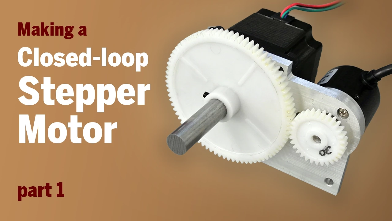
Converting a Stepper Motor to Closed-Loop with Encoder
@KrisTemmermanNP
345.7K views•2015-01-16

30:32
Ultrasonic Transducers: Resonant Frequency Measurement and Horn Design
@imajeenyus42
229.9K views•2017-02-22

54:16
Polymer Environmental Degradation: Mechanisms & Stabilization
@iit
1.8K views•2012-07-10

33:39
How a Student's Question Saved a NYC Skyscraper from Collapse
@veritasium
22.8M views•2025-04-26
Related Study Plans & Knowledge Roadmaps
Structured learning paths in Engineering
engineering
Building Acoustic Levitators: Physics & Arduino
01The Physics of Sound and Standing Waves
02Piezoelectric Transducers and H-Bridge Drivers
03Arduino Programming: Generating 40 kHz Signals
+ 2 more learning modules
14h5 modules
Explore Roadmap
engineering
Building Peltier Cloud Chambers: Particle Tracks
01Cosmic Rays & Cloud Chamber Physics
02Thermoelectric Cooling (TEC) Fundamentals
03Custom Liquid-Cooling Loop Design
+ 2 more learning modules
18h5 modules
Explore Roadmap
engineering
Yagi-Uda Antennas: Modeling, Build & VNA Test
01Introduction to RF and Antenna Fundamentals
02Yagi-Uda Antenna Design Principles
03Antenna Modeling and Simulation in 4NEC2
+ 2 more learning modules
18h5 modules
Explore Roadmap
engineering
ECG Monitor Design: Op-Amps, Filters & Noise
01Electronics & Breadboard Basics
02Op-Amps and Instrumentation Amplifiers
03Bioelectricity and ECG Fundamentals
+ 2 more learning modules
18h5 modules
Explore Roadmap