Building Peltier Cloud Chambers: Particle Tracks
Learning Goal: Design, build, and optimize a thermoelectric cloud chamber using multi-stage Peltier coolers and a custom liquid-cooling loop to achieve stable sub-zero temperatures (below ) for visualizing cosmic ray particle tracks.
Prerequisites
- Basic understanding of DC electrical circuits (voltage, current, power).
- Familiarity with hand tools and basic assembly.
- Safe handling protocols for high voltage (1kV+) and isopropyl alcohol (99% purity).
Estimated Total Study Time: 18 Hours
Module 1: Cosmic Rays & Cloud Chamber Physics
This module establishes the scientific foundation of your build. You will study how high-energy particles (cosmic rays, alpha particles, beta particles) interact with matter, how ionizing radiation strips electrons from air molecules, and how a supersaturated alcohol vapor vaporizes and condenses around these ions to reveal subatomic tracks.
Recommended Videos
- Why this video is valuable: This video provides a highly visual, practical introduction to building a baseline cloud chamber. It explains the mechanics of creating a supercooled, supersaturated vapor layer of isopropyl alcohol and shows how ionizing particles trigger localized condensation along their paths. It is an ideal starting point to grasp the relationship between temperature differential and track formation.
- Why this video is valuable: To calibrate and evaluate your chamber, you must recognize what different particles look like. This video illustrates how distinct radiation types produce unique tracks. You will learn to differentiate the straight, thick paths of alpha particles (highly energetic helium nuclei) from the thin, wispy, erratic paths of beta particles (high-speed electrons) and cosmic muons.

- Why this video is valuable: Host Brian Cox demonstrates the fundamental setup using dry ice, proving how a simple thermal gradient transforms invisible background cosmic radiation into visual tracks. It reinforces the scientific importance of the cloud chamber as one of the earliest particle detectors in modern physics.
Knowledge Checkpoint
- Explain how a charged particle creates a visible trail of droplets in a supersaturated alcohol vapor.
- Describe the difference in track geometry between an alpha particle and a beta particle/muon.
- Explain why a strong temperature gradient (warm at the top, sub-zero at the bottom) is necessary to sustain a sensitive active detection layer.
Module 2: Thermoelectric Cooling (TEC) Fundamentals
To eliminate the need for dry ice, you will use solid-state Thermoelectric Coolers (TECs) that utilize the Peltier effect. This module covers the physics of semiconductor junctions, electrical power requirements, and the thermal mechanics of stacking multi-stage Peltiers to achieve a large temperature differential ().
Important Engineering Gap Note: Standard videos often gloss over the math of cascading Peltiers. In a stacked configuration, the bottom stage must dissipate both the heat pumped from the chamber and the electrical power consumed by the upper stage (). If you stack identical modules (e.g., two TEC1-12706 units running at the same voltage), the bottom stage will saturate, overheat, and cause thermal runaway. You must match the stages: the bottom stage must have a significantly higher thermal capacity () than the top stage (ideally a 3:1 or 4:1 ratio, such as a 12706 top stage paired with a high-power 12715 or multiple modules on the bottom stage).
Recommended Videos
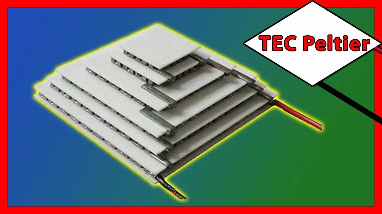
- Why this video is valuable: This video is an essential watch for this curriculum. It explains how to correctly wire and stack thermoelectric modules in series vs. parallel, providing the physical foundation of how multi-stage cooling works to achieve extreme temperature differences.
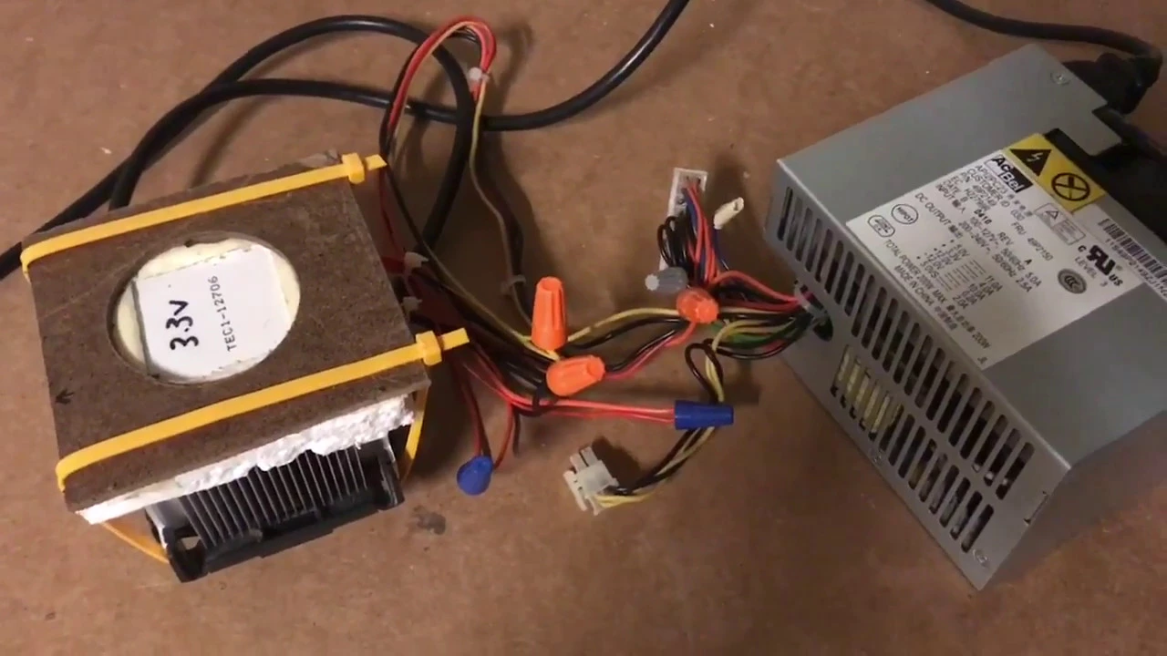
- Why this video is valuable: A practical demonstration of stacking multiple TEC1-12706 modules to reach . It shows how varying the input voltages across the stacked modules is critical to balancing the thermal load across the stages.
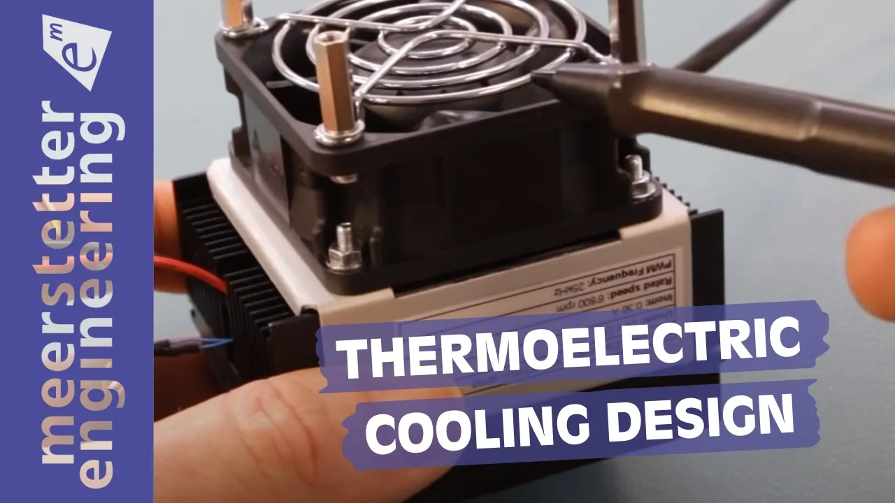
- Why this video is valuable: This video provides the deep engineering theory required to analyze Peltier performance graphs, calculate , and design a balanced solid-state cooling system while avoiding common design errors that lead to thermal runaway.
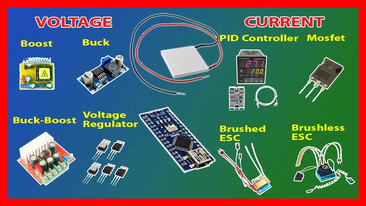
- Why this video is valuable: Peltiers are highly sensitive to power quality. This video covers the electrical aspects of powering TECs, including why high ripple from poor PWM control can degrade performance and how to use buck converters and regulated DC power supplies to maintain high cooling efficiency.
Knowledge Checkpoint
- Calculate the total heat load () of a two-stage Peltier stack where Stage 1 (top) has a cooling load of and consumes of electrical power.
- Explain why running two identical TEC1-12706 modules in a physical stack at a uniform 12V is highly inefficient and likely to fail.
- Why is continuous DC current preferred over raw, low-frequency PWM signals for powering Peltier elements?
Module 3: Custom Liquid-Cooling Loop Design
Solid-state cooling is only as good as your hot-side heat dissipation. Because a multi-stage Peltier stack generates massive amounts of waste heat (often exceeding ), basic passive heatsinks will quickly saturate. This module details the design of a custom liquid-cooling loop consisting of high-flow water blocks, low-vibration pumps, and high-performance radiators to maintain water temperatures near ambient.
Engineering Gap Note: PC water blocks are designed to sit on silicon CPUs with integrated heat spreaders under moderate pressure. When mating a copper water block to a ceramic Peltier module, you must apply high, uniform clamping pressure (approximately depending on the module) to minimize thermal contact resistance. Use a high-quality, non-conductive thermal paste (applied in a thin, uniform layer) and a rigid clamping mechanism with spring-loaded bolts to prevent fracturing the fragile bismuth telluride pellets inside the TEC.
Recommended Videos
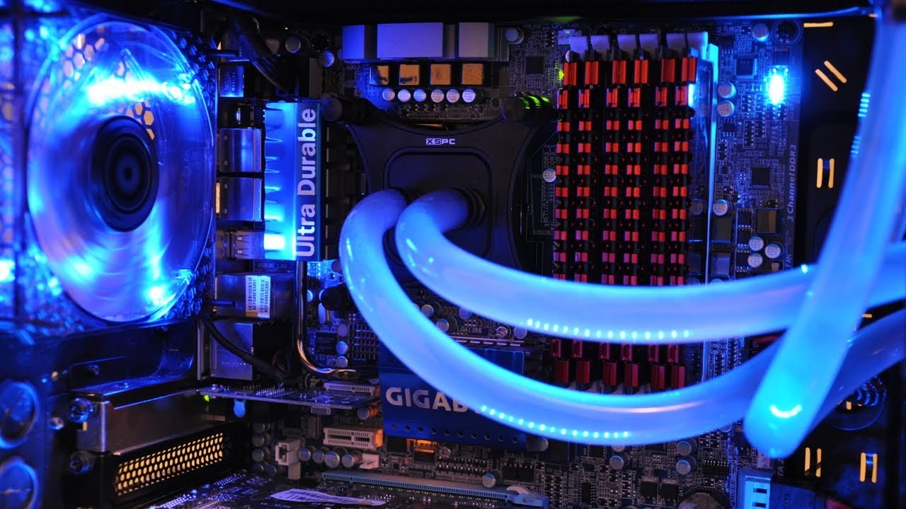
- Why this video is valuable: A quick, comprehensive primer on the fundamental parts of a liquid loop (water blocks, pumps, reservoirs, and radiators). This establishes the fluid dynamics knowledge required for your build.

- Why this video is valuable: A practical assembly guide that details how to route tubing, handle fittings, avoid leaks, and structure a loop. This practical walk-through prevents catastrophic water damage when integrating custom liquid cooling with high-power electronics.
- Why this video is valuable: This video focuses on heat transfer thermodynamics across radiators. It explains the importance of temperature differentials ( between coolant water and ambient air) and teaches you how to optimize fan curve configurations to maximize radiator efficiency.
Knowledge Checkpoint
- Sketch a complete plumbing schematic of a liquid cooling loop containing a water block, pump, reservoir, and radiator, showing the correct flow direction.
- How does uneven clamping pressure across a Peltier module degrade its cooling performance and risk physical destruction of the module?
- What is the cooling capacity rule-of-thumb for sizing radiators, and why is a or radiator recommended for a multi-stage Peltier system?
Module 4: Chamber Assembly, Alcohol Management & High-Voltage Clearing Grid
With your thermal engine complete, you will now design and assemble the active chamber. This module covers physical chamber construction, managing the alcohol vapor density gradient, and engineering a critical, often-overlooked safety system: the high-voltage electrostatic clearing grid.
   [ Warm Top Lid (Heated to +35°C via PTC / Resistors) ]
   [ High-Voltage Copper Ring (+) (Charged to +1kV to +3kV) ]
                    |
                    |  Active Detection Zone
                    |  (Supersaturated Alcohol Vapor)
                    v
   [ Black Metal Bottom Plate (-) (Chilled to -26°C via TECs) ]
The Engineering of the Electrostatic Clearing Grid
As cosmic rays pass through the chamber, they leave behind ionized tracks. However, ambient ions and dust accumulate over time, creating a background "fog" of condensation that ruins track contrast.
An electrostatic clearing grid solves this by establishing a high-voltage, low-current electric field across the chamber.
- Physical Layout: Suspend a bare copper wire ring directly below the top chamber lid (positive terminal) and ground the black metal bottom plate (negative terminal).
- Electrical Setup: Connect a high-voltage DC-DC step-up converter (producing to ) between the ring and the plate.
- Safety Critical Implementation: To make this system completely safe, you MUST place a high-value current-limiting resistor (minimum to , rated for high voltage) in series with the positive high-voltage lead. This limits any accidental discharge current to micro-amps, preventing dangerous electrical shocks while maintaining the electrostatic field.
Managing the Vapor Gradient
To keep the top of the chamber warm and prevent condensation on the viewport, you must maintain a steep temperature gradient. While the bottom plate is frozen to below by the TECs, the top lid should be actively warmed to to using low-power resistive heaters or a PTC element. This keeps the isopropyl alcohol evaporating at the top and traveling downward to condense near the sub-zero bottom plate.
Recommended Videos

- Why this video is valuable: This video showcases a functioning, compact thermoelectric cloud chamber. It serves as a visual layout reference for integrating the chamber envelope with a stacked Peltier engine.

- Why this video is valuable: This short clip explains the molecular properties of alcohol. You will learn why isopropyl alcohol is used—its polar molecular structure (dipole moment) makes it highly attracted to ionized air molecules, prompting rapid condensation along particle tracks.

- Why this video is valuable: This video provides an educational analysis of high-voltage generator circuits. By looking at the schematics and power-limiting techniques shown here, you will learn how to safely implement and wire a high-voltage electrostatic field for your clearing grid without creating shock hazards.
Knowledge Checkpoint
- Draw a complete electrical schematic of the high-voltage clearing grid, detailing the placement of the safety current-limiting resistor.
- Why is pure isopropyl alcohol highly preferred over lower-purity rubbing alcohols () or water in a cloud chamber?
- Explain how heating the top chamber lid prevents dew-point condensation on the viewing window and helps maintain the active supersaturation zone.
Module 5: System Integration, Optimization & Calibration
The final phase involves integrating your liquid cooling loop, multi-stage Peltier assembly, chamber body, heating element, and high-voltage electronics into a single cohesive system. You will learn how to troubleshoot thermal insulation leaks, calibrate temperature controllers, and optimize the environment for recording high-contrast cosmic ray particle tracks.
Calibration and Optimization Checklist
- Thermal Insulation: Ensure the sides of the Peltier stack are completely sealed using closed-cell neoprene foam insulation. If ambient air reaches the chilled cold plate, condensation and ice bridging will occur, creating a thermal short-circuit that prevents the plate from reaching sub-zero operating temperatures.
- Sensor Calibration: Calibrate your NTC thermistors or PT100 sensors. Ensure the controller offset is adjusted so that the temperature readouts accurately match a physical reference thermometer at (ice bath test).
- Optimizing Lighting: Particle tracks are highly delicate. Use a high-intensity, low-heat LED strip mounted at a shallow side angle ( relative to the bottom plate) to illuminate the condensation droplets against the black background via Tyndall scattering.
Recommended Videos

- Why this video is valuable: Explains how to set up, program, and calibrate digital temperature controllers (such as the W1209 series). This is critical for controlling both your top lid heating element and monitoring your bottom plate temperature to prevent cooling-loop over-chilling.
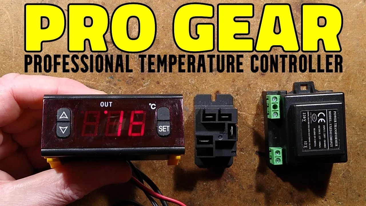
- Why this video is valuable: Provides a detailed look at commercial temperature controller calibration settings (such as adjusting the offset parameter 'E5'). This ensures your temperature readings are highly accurate.
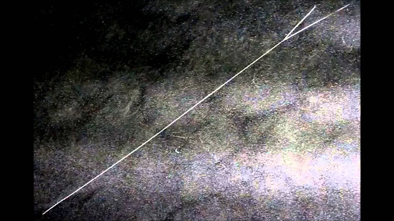
- Why this video is valuable: A diagnostic reference video. This high-contrast footage shows what properly calibrated and optimized cosmic ray tracks look like under correct lighting conditions. It acts as the visual standard for your finished project.
Knowledge Checkpoint
- Describe the symptoms of an "ice bridge" thermal short-circuit on your Peltier stack and outline how to fix it using closed-cell insulation.
- Explain how to calibrate a temperature controller that reads when immersed in a reference ice bath.
- Why is high-intensity, shallow-angle lighting necessary to see the tracks, and why should you avoid overhead light sources?
Course Map
This map outlines the ideal progress path through the curriculum:
Key People Index
- Charles Thomson Rees Wilson (C.T.R. Wilson): Scottish physicist who invented the cloud chamber in 1911. His work on visualizing ionizing radiation tracks earned him the Nobel Prize in Physics in 1927.
- Jean Charles Athanase Peltier: French physicist who discovered the thermoelectric effect in 1834, proving that running an electrical current through a junction of dissimilar conductors creates a temperature differential.
- Thomas Johann Seebeck: Physicist who discovered the complimentary thermoelectric effect (Seebeck Effect) in 1821, which forms the basis for thermocouple temperature sensors used in our calibration modules.
Final Self-Assessment
Complete this checklist once your system is fully built and operational:
- Liquid Loop Integrity: The liquid-cooling loop is run for 60 minutes independently of the electronics with zero leaks or moisture accumulation.
- Clamping Check: The Peltier stack is physically secured using a rigid spring-bracket clamping mechanism with flat, thin layers of high-performance thermal paste.
- Thermal Insulation: The cold-side plate is thermally isolated from the hot-side water block using closed-cell neoprene foam insulation to prevent ice bridging.
- Temperature Target: The bottom cold plate successfully reaches and holds a stable temperature below under load.
- Top Lid Temperature: The top lid heating element maintains a stable surface temperature between and .
- Safety Clearing Grid: The high-voltage clearing grid is wired with a high-resistance safety resistor ( to ) and successfully clears background fog.
- Tyndall Lighting: Side-mounted LED illumination is adjusted to a shallow angle, rendering fine condensation droplets bright against the black background.
- Vapor Saturation: A steady rain of fine alcohol droplets is visible falling toward the bottom plate, creating a stable, sensitive detection zone.
- Track Observation: You can identify and record at least three distinct cosmic ray or background muon tracks within a 10-minute observation window.