Building Acoustic Levitators: Physics & Arduino
Learning Goal: Design, assemble, and calibrate a single-axis ultrasonic acoustic levitator using an array of 40 kHz transducers, a dual H-bridge driver circuit, and an Arduino to generate standing waves for suspending and manipulating micro-particles.
- Prerequisites: Basic knowledge of electronics (voltage, current, parallel circuits), familiarity with the Arduino IDE, and foundational physics (wave properties).
- Estimated Total Study Time: 14 Hours
Module 1: The Physics of Sound and Standing Waves
This module establishes the foundational acoustic physics required to understand levitation. You will learn how high-frequency sound waves travel through gaseous mediums, undergo constructive and destructive interference, and form stationary pressure profiles (standing waves). You will explore the physical characteristics of "nodes" (low-pressure points) and "antinodes" (high-pressure points) to understand how acoustic radiation pressure counteracts gravitational force.
Recommended Videos
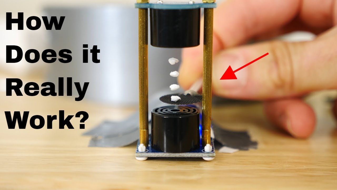
- Why this video is valuable: This video provides an intuitive physical visualization of acoustic standing waves. It breaks down the mechanical interaction between transducers and reflectors, showing how air molecules behave within the resonant cavity to form high-pressure "invisible shelves" that suspend matter.

- Why this video is valuable: Physics Girl demonstrates a practical implementation of a single-axis levitator, linking acoustic wave theory to an actual physical build. She explains the necessity of using high-frequency (ultrasonic) sound to keep the physical apparatus compact and quiet enough for safe human environments.

- Why this video is valuable: A short, high-fidelity demonstration showing the exact physical position of suspended beads within a standing wave pattern. It serves as an excellent reference for what a properly aligned standing wave looks like in practice.
Knowledge Checkpoint
- Explain the difference between an acoustic node and an antinode. Where exactly do levitated particles sit?
- Calculate the wavelength () of a 40 kHz sound wave in air at room temperature (, speed of sound ).
- Describe how acoustic radiation pressure counteracts gravity to hold a particle stationary.
Module 2: Piezoelectric Transducers and H-Bridge Drivers
To build an acoustic levitator, you must generate high-intensity ultrasonic waves. This module covers the operation of 40 kHz piezoelectric transducers, which convert high-frequency electrical signals into mechanical vibrations. You will also study the H-bridge driver topology (specifically the L298N driver), which is used to amplify the weak digital signals of a microcontroller to drive capacitive transducer loads with high-voltage alternating current.
Recommended Videos

- Why this video is valuable: This brief technical explanation from Texas Instruments shows how piezoelectric crystals contract and expand in response to an applied voltage, creating the microscopic high-frequency pressure waves required for ultrasonic output.
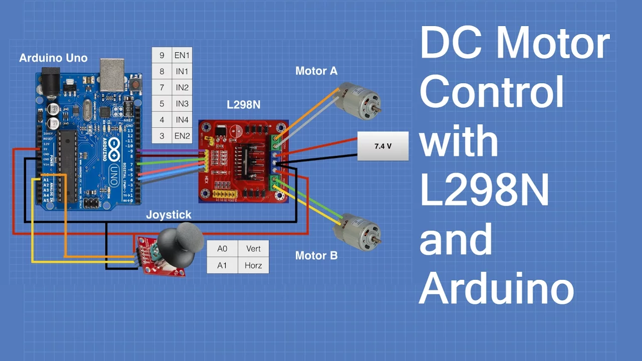
- Why this video is valuable: While typically used for DC motors, the L298N H-bridge driver is perfect for acoustic levitation because it can rapidly switch polarities. This video explains the internal logic, pinouts, and switching characteristics of the L298N module, helping you understand how it processes drive signals.

- Why this video is valuable: This video breaks down a schematic of an H-bridge circuit, explaining how alternating diagonal pairs of transistors switch current direction through a load. This provides excellent foundational knowledge for understanding signal inversion in driver circuits.
Independent Search & Exploration
- Gap Note: Standard H-bridge tutorials focus primarily on low-frequency inductive loads (DC motors). For ultrasonic levitation, the L298N must drive highly capacitive 40 kHz transducer arrays.
- Recommended Search Query:
DIY ultrasonic levitator L298N driver circuit schematicto study how to bypass standard motor driver filtering for high-frequency output.
Knowledge Checkpoint
- How does a piezoelectric crystal behave when an alternating current (AC) is applied across its terminals?
- Draw a simple schematic of an H-bridge circuit and identify which diagonal transistor pairs must be active to alternate current direction.
- What is "shoot-through current" in an H-bridge, and why must you prevent both high and low-side transistors on the same half-bridge from turning on simultaneously?
Module 3: Arduino Programming: Generating 40 kHz Signals
A standard Arduino Uno’s analogWrite() function operates at a default frequency (~490 Hz or ~976 Hz) that is far too low for acoustic levitation. In this module, you will learn to bypass the standard Arduino library and write register-level code to configure the ATmega328P internal timers. You will generate a precise 40 kHz PWM output, configure complementary (out-of-phase) square waves to drive the H-bridge, and insert "dead-time" to prevent electrical damage.
Recommended Videos

- Why this video is valuable: This video offers a clear, register-level explanation of how Arduino Timer Control Registers (TCCRA and TCCRB) and prescalers configure precise timer interrupts. Understanding these internal registers is critical for setting up the high-frequency clock cycles required for a 40 kHz output.

- Why this video is valuable: Julian Ilett provides a practical walkthrough on modifying the default PWM frequencies by directly manipulating the timer prescaler bits. This guide is essential for transitioning from low-frequency DC motor control to high-frequency ultrasonic signals.

- Why this video is valuable: This advanced tutorial explains how to generate complementary (180-degree out-of-phase) square waves with integrated dead-time using microcontroller timers. This concept is vital for safely driving the dual inputs of an H-bridge driver without causing short circuits.
Independent Search & Exploration
- Gap Note: Direct register programming varies significantly between Arduino architectures (e.g., ATmega328P on the Uno vs. SAMD21 on the Nano 33 IoT).
- Recommended Search Query:
Arduino complementary PWM 40kHz acoustic levitatorto find code templates written specifically for your hardware.
Knowledge Checkpoint
- Which Timer Control Registers on the ATmega328P are used to modify the frequency of Digital Pins 9 and 10?
- Why must the two signal lines driving a single H-bridge driver be exactly 180 degrees out-of-phase (complementary)?
- Define "dead-time" in H-bridge control and explain why it is essential for high-frequency switching applications.
Module 4: Mechanical Assembly and Transducer Alignment
This module covers the physical design, structural assembly, and electrical wiring of your acoustic levitator. You will learn to construct a physical frame (often 3D printed or laser-cut) that positions two opposing transducer arrays at a precise mechanical distance. You will also learn the practical steps of wiring multiple 40 kHz transducers in parallel with matched acoustic polarity (phase alignment).
Recommended Videos
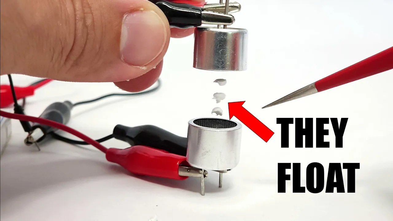
- Why this video is valuable: This video is a step-by-step build guide for a dual-array acoustic levitator. It demonstrates physical assembly, wiring routing, external power connections via the Arduino's VIN pin, and basic testing.

- Why this video is valuable: This video clearly explains the principles of parallel wiring: connecting all positive terminals together and all negative terminals together. This same wiring technique is used to connect multiple 40 kHz ultrasonic transducers in parallel to ensure they operate in phase.

- Why this video is valuable: This video explains how to wire multiple elements in series-parallel configurations to manage power distribution. This is highly useful if you want to scale up your levitator into a larger transducer array.
Independent Search & Exploration
- Gap Note: Ensuring all parallel transducers are wired with matched physical polarity is crucial; if some transducers are wired backwards, their acoustic waves will cancel each other out, ruining the standing wave.
- Recommended Search Query:
how to wire 40kHz ultrasonic transducers parallel phaseto find detailed visual guides on identifying the positive and negative terminals on bare piezoceramic transducers.
Knowledge Checkpoint
- Why must the distance between the top and bottom transducer arrays be a precise multiple of the acoustic half-wavelength ()?
- If you wire two transducers in parallel with opposite polarity, what happens to the resulting acoustic wave?
- How do you identify the positive and negative terminals of a 40 kHz piezoelectric transducer?
Module 5: Calibration, Testing, and Particle Manipulation
Once assembled, your levitator must be carefully calibrated. This final module covers how to use an oscilloscope to check the output voltage of your H-bridge driver, tune the frequency to match the transducers' resonant frequency (~40 kHz), and mechanically align the acoustic axes to maximize standing wave pressure. You will also learn techniques for introducing and manipulating micro-particles (such as expanded polystyrene beads).
Recommended Videos
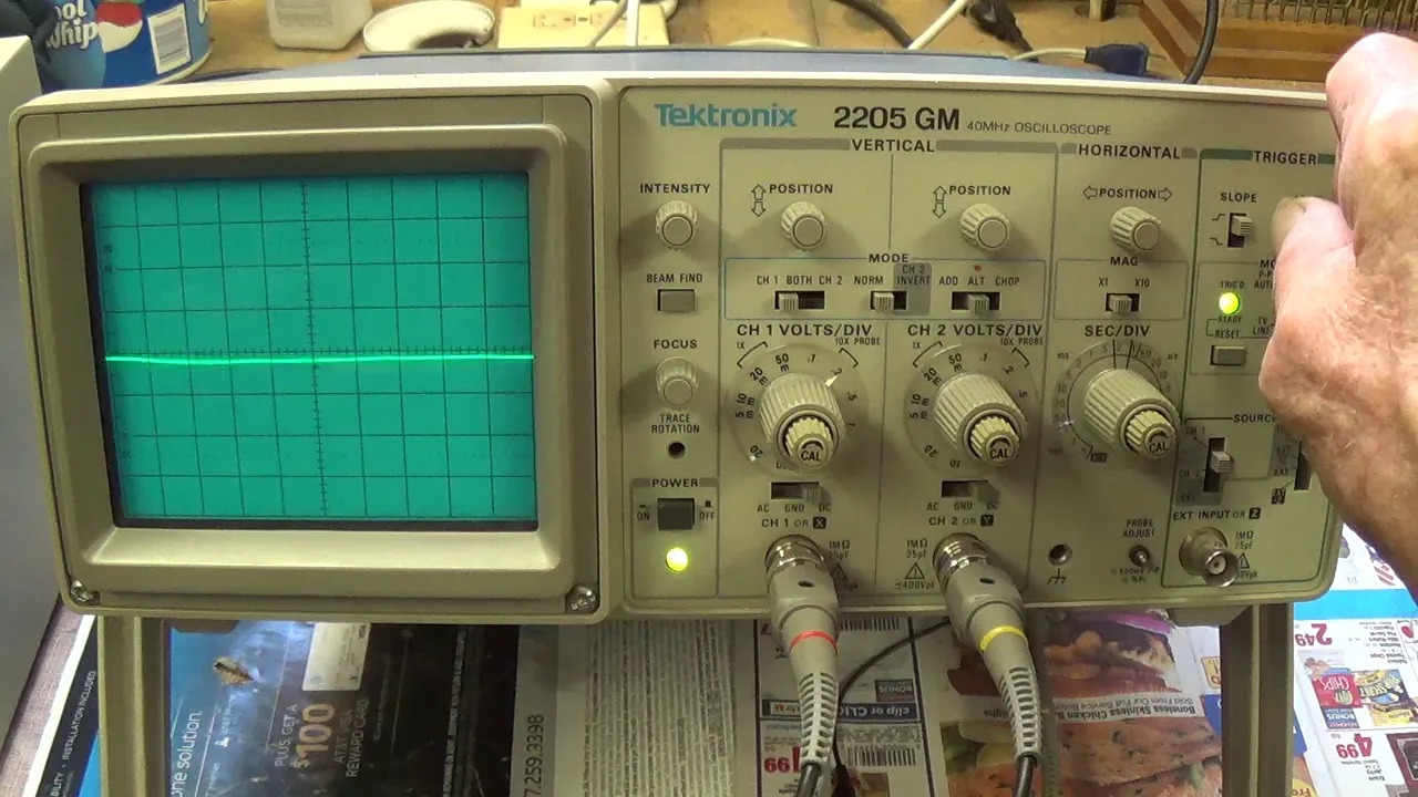
- Why this video is valuable: To calibrate your acoustic levitator, you must measure your drive signal. This video teaches you how to use an oscilloscope to measure voltage amplitudes and calibrate probes using a square wave generator.

- Why this video is valuable: This deep dive shows how to measure the exact resonant frequency of an ultrasonic transducer using an oscilloscope and signal generator. It provides the technical foundation needed to tune your Arduino code to match your transducers' resonant frequency.

- Why this video is valuable: A demonstration of particle trapping, physical manipulation, and spatial control within a phased ultrasonic array. It shows how precision phase shifts can move particles along an acoustic axis.
Independent Search & Exploration
- Gap Note: Budget levitator builds often lack an oscilloscope. You can calibrate your setup physically by tuning a variable resistor or adjusting the mechanical distance until particles successfully suspend in mid-air.
- Recommended Search Query:
oscilloscope calibration acoustic levitator standing waveoracoustic levitation troubleshooting guide particles dropfor specific step-by-step physical alignment procedures.
Knowledge Checkpoint
- How do you use an oscilloscope to verify that your Arduino and H-bridge driver are outputting a clean 40 kHz square wave?
- What physical symptoms indicate that your upper and lower transducer arrays are out of alignment?
- Describe the technique for safely releasing a tiny polystyrene bead into an active acoustic node without disrupting the standing wave.
Course Map
Key People Index
- Dr. David Deak: Pioneer in acoustic wave chamber development and low-frequency resonant wave levitation systems.
- Asier Marzo: Leading researcher in acoustic holographic levitation and contactless robotic manipulation at the University of Bristol and UpnaLab.
Final Self-Assessment
- I can explain the physical principles of sound waves, standing waves, nodes, and antinodes.
- I can calculate the acoustic half-wavelength () in air for any given ultrasonic frequency.
- I understand how a piezoelectric ceramic transducer converts electrical alternating voltage into mechanical vibrations.
- I can describe how an H-bridge driver (such as the L298N) functions to reverse polarity across a capacitive load.
- I can configure the Timer registers on an ATmega328P to change default PWM outputs to a precise 40 kHz frequency.
- I can write Arduino code that outputs dual out-of-phase (complementary) signals with necessary dead-time.
- I know how to wire multiple ultrasonic transducers in parallel with matched acoustic phase polarity.
- I have assembled a physical frame holding two opposing transducer arrays separated by a multiple of the acoustic half-wavelength.
- I can use an oscilloscope to verify output frequency, peak-to-peak voltage, and phase matching on my driver circuit.
- I can successfully calibrate, align, and troubleshoot my levitator to stably suspend small polystyrene beads in mid-air.