

![[임베디드 기초 뿌수기 5-1] 임베디드의 시작, GPIO란?](https://i.ytimg.com/vi_webp/HD4nXj2Dm5k/maxresdefault.webp)




![Timer con Arduino [Parte 1] ❤️ REGISTROS del Micro! # 015](https://i.ytimg.com/vi_webp/GFjwe4UhcZc/maxresdefault.webp)







![Silniki DC | cz.2 - Mostek H | #64 [Podstawy]](https://i.ytimg.com/vi/YMECxKCmrfw/maxresdefault.jpg)


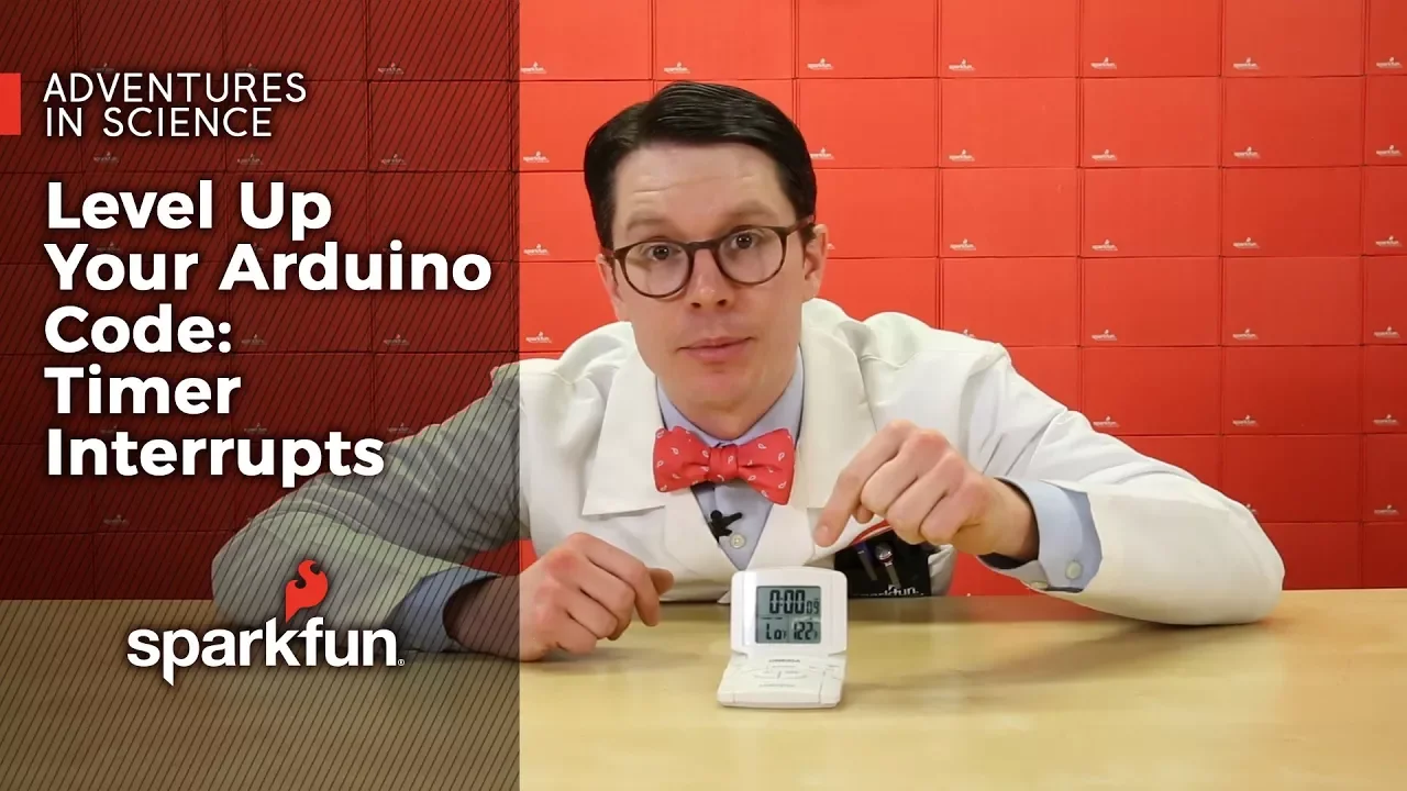

The Arduino's PWM frequency varies by pin: pins 5 and 6 operate at 976Hz using Timer 0, while pins 3, 9, 10, and 11 run at 490Hz using Timers 1 and 2; these frequencies can be modified by adjusting the timer prescalers in the TCCRnB register, though this may interfere with timing functions like millis() and delay().
Arduino PWM Frequency Change Tutorial: Timer Prescaler Guide
Added:Fundamentals of Pulse Width Modulation (PWM), including duty cycle, frequency, and how the standard Arduino analogWrite() function works.
Basic AVR microcontroller architecture, specifically how hardware Timers (Timer0, Timer1, and Timer2) relate to physical GPIO pins on the ATmega328P.
Concepts of register manipulation and bitwise operations (AND, OR, bit-shifting) in C/C++ to configure hardware registers directly.
Familiarity with interpreting hardware datasheets (like the ATmega328P datasheet) to locate register maps and prescaler configuration tables.
Analyzing and mitigating the side effects of timer modification, such as the disruption of time-dependent functions like millis(), delay(), and the Servo library.
Advanced timer configurations, including Fast PWM versus Phase-Correct PWM modes, and configuring custom TOP values using input capture registers (ICR1) for precise frequency control.
Practical applications of high-frequency PWM in power electronics, such as eliminating audible switching noise (whine) in DC motor control and optimizing buck/boost converter efficiency.
Utilizing Timer Interrupt Service Routines (ISRs) to execute precise, time-critical code independent of the main loop execution.
156.4K views1.1Klikes11:09Original Release: 2013-08-16
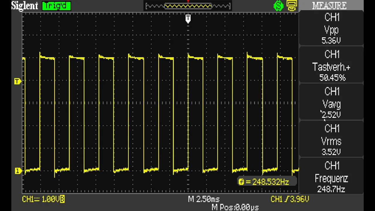
now I want to uh play around with pwm on the Arduino um because I want to drive a buck converter but I want to drive it at a high frequency and the Arduino has a fixed pwm frequency you can vary the pulse width The Marked a space ratio but the frequency is fixed so the first thing I wanted to do is look at the pwm outputs and uh see what the standard frequency is so here's um a little Arduino Nano it's a clone not a genuine one and uh onto analog a z which is uh this pin here and ground and VCC I've attached a little potentiometer module now you got to watch these potentiometer modules because as you can see um the uh wiper is not on the center pin positive is on the center pin and I didn't realize that initially and I plugged it in uh as you would a normal pot and smoke started coming out but anyway once I worked out how to do it um you just uh let's get rid of the magnifying glass you just connect the uh potentiometer up to analog a z and VCC and ground now I've opened a new Arduino sketch but I'm going to go to uh examples and there's one called analog read serial so I'm going to close the original sketch and I'm just going to work from analog read serial so in fact I'm going to load this into the Arduino now let's uh make sure that goes in there are the TX and RX lights and that's gone in okay so now what should happen is if I put up the serial monitor I'm getting a stream of numbers coming out there and if I turn the potentiometer those numbers vary between zero at one end and 1024 1023 at the other so it's reading the potentiometer value and converting it to a digital number so the next thing to do is to uh send the uh analog value from the potentiometer out to one of the pwm pins now only certain of the digital pins are pwm and on the Nano it's a bit difficult to see uh on on a normal Ard know you've got a little tilder on the Nano there's just a DOT so D3 is pwm D5 D6 D9 d 10 and d111 are all pwm pins um D13 isn't which is a shame because there's already an LED on D13 which is the uh L LED that one there um but we can't pwm that so I'm going to have to put an external LED on so I think what I'll do for the moment is I'll put it on I don't know say D9 so I've gone to the ardino website and the reference section and I'm looking at analog right and analog right is the way you set a PIN to pwm um and the syntax is in the example below we need to set a pin as an output in the setup function and we need to do an analog write of uh whatever pin we choose to EV value of our choice now because pwm is runs from not to 2555 and the uh analog read runs from not to 1023 we have to divide the value by four so I've inserted into my sketch the analog right line which is here analog right to pin n which is one of the pwm pins sensor value which I've got from doing an analog read which is up here sensor value is analog read a0 and dividing it by four to convert the range not 1023 to n255 now interestingly I forgot to put up in the setup setting uh pin 9 as an output but it doesn't seem to matter so when you do an analog WR it must do that for you because if we look down here on the board my LED is on and if I turn the potentiometer I can vary the brightness of the LED so now I've put my oscope across the LED and you can see on the screen that we've got um a signal and dead in the middle burnt my potentiometer anyway that works now the frequency on channel one is 49 HZ and if you look at the documentation on Arduino you'll see that they do uh quote the pwm frequency as 490 HZ but I've been digging a bit further into this and it's not the same on all the digital pwm pins if you go to playground. arduino.cc slode pwm frequency you've got a piece of uh code here where you can actually alter the um frequency of the pwm outputs now it makes reference to a post this one arduino.cc yab to uh so and so so and so so I've gone to that and it's called varying the pwm frequency for timer Z or timer 2 and there's a chap here uh what's his name mace gr who has put down all the frequencies that you can uh set up on the various digital pins by putting in different devicer figures and the frequencies are different for Pins 5 and six pins 9 and 10 pins 11 and three so at the moment I'm looking at Pin nine here and that appears to use timer 1 but pins five and six use timer zero and pins 11 and three use timer 2 so I've put a second LED onto the breadboard on digital pin D5 which is also a pwm pin so I'm now looking at D9 and D5 and in the code I've put a second analog right line putting the same uh pulsewidth data but I've got it now on pins 9 and five and if I look at the scope um I can't trigger off the second one because it's not a direct uh multiple of the first one but if you look at the two frequencies on channel one I've got 490 Herz and on channel 2 I've got 976 Herz now that sort of ties up with this pin 9 uh with a divisor of 64 488 Herz well I've got 490 and then up here pin five with a divisor of 64 9 976 HZ well I've got 976 HZ so that makes sense now if you scroll down a bit you've got this chat meon 83 saying MGR I'm afraid that the frequencies in your post for Pins 3 9 10 11 are a little off the correct formula is FAL clock / 510n and then he says that gives frequency of 490 Herz so that's where the M the mystery is it is actually 490 HZ for Pins 3 9 10 and 11 not 488 Herz now I wanted a frequency of about 15 khz and unfortunately that doesn't appear anywhere in any of these three tables there is um in the top table so that's timer zero uh pins 5 and six about 8 khz or 62 and2 khz and in the bottom two tables there's a 31 khz or or 4 khz so I'm going to have to compromise and go for 31 khz so on my pin 9 which is my blue LED that's on D9 I'm going to try and change the frequency to 31 Kilz so there's pin 9 so it's timer one and I'm just going to copy that line tccr 1B equals tccr 1B and uh that binary value or setting and setting will be uh for 31 khz o x01 the top one in that table so I've pasted that line of code tccr 1B equals T tccr 1B uh the binary number and the ox1 into my setup um function and the compiler seemed happy with that and uh I've still got the ability to vary the brightness of both LEDs on the potentiometer and on the scope we now have on channel one I changed the time base a bit there 31.3 it's reporting um what's it say on here 31250 okay my scope's slightly over reading I'm getting 3137 but anyway it's 31 khz and I've still got 976 Hertz on my channel 2 which was the green LED which was on digital pin D5 so that's it I've changed the frequency of the pwm on one of the timers to 31 khz now you have to be aware that this can interrupt um on timer one certain functions if you change timer zero it affects Millies and the delay function timer one I'm not entirely sure what the uh effects will be but just watch out for um side effects
Up Next

82:01
Arduino PWM Tutorial: Analog Output & RGB LED Control
@rendikurniawan6063
268 views•2020-05-09

12:54
Triumph of Orthodoxy Icon: Byzantine Art & History Explained
@BenCallan
2.1K views•2024-08-06

9:49
FastAPI vs Flask vs Django: Choosing the Right Python Web Framework
@TechWithTim
302.5K views•2024-05-26

1:42
Game of Thrones Opening Credits: A Cinematic Analysis
@gameofthrones
46.3M views•2011-04-18
Related Study Plans & Knowledge Roadmaps
Structured learning paths in General & Interdisciplinary Studies
general-studies
Elevator Engineering: History, Physics & Cities
01From Hoists to Safety Brakes: The Dawn of Vertical Lift
02Hydraulic vs. Traction: The Engineering Physics of Elevators
03Modern Speed, Safety, and Algorithms
+ 2 more learning modules
12h5 modules
Explore Roadmap
general-studies
Rubber: Material Science, History & Geopolitics
01Origins of Natural Rubber & Mesoamerican History
02The Chemistry of Natural Rubber & Vulcanization
03The Geopolitics of the Rubber Boom & Colonization
+ 2 more learning modules
12h5 modules
Explore Roadmap
general-studies
Containerization: Evolution, Logistics & Trade
01Ancient Trade & Bulk Cargo: Amphorae to Barrels
02The Industrial Revolution & Cardboard Packaging
03The Containerization Revolution: Malcom McLean
+ 2 more learning modules
12h5 modules
Explore Roadmap
general-studies
Textile Tech: Evolution, Labor & Global Impact
01Pre-Industrial Textiles: Handloom & Cottage Industry
02Mechanization: The Spinning Jenny to the Power Loom
03The Factory System & Global Labor Transformation
+ 2 more learning modules
10h5 modules
Explore Roadmap