
















![Timer con Arduino [Parte 1] ❤️ REGISTROS del Micro! # 015](https://i.ytimg.com/vi_webp/GFjwe4UhcZc/maxresdefault.webp)

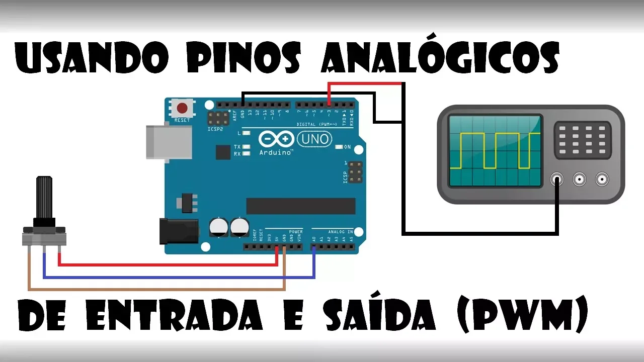
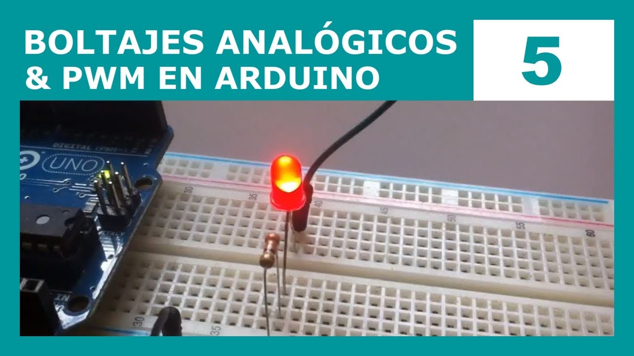
Pulse Width Modulation (PWM) is a technique used in Arduino to generate variable average voltage output from digital pins by rapidly switching the output between high and low states. The duty cycle, expressed as a percentage of the high state within one period, determines the average voltage: 0% duty cycle produces 0V, 50% produces approximately 2.5V, and 100% produces 5V. Arduino uses specific timer pins (3, 5, 6, 9, 10, 11) for PWM generation, with the analogWrite() function accepting values from 0 to 255 to control the duty cycle. PWM is commonly used for controlling LED brightness, motor speed, and other applications requiring variable power output.
Arduino PWM Tutorial: Analog Output & RGB LED Control
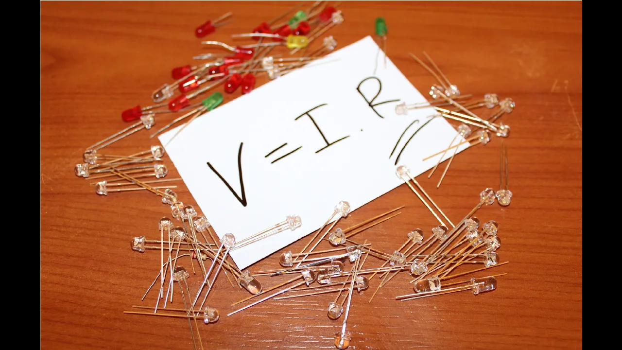
Added:Basic electronics concepts, including voltage, current, resistance, and the application of Ohm's Law to prevent damaging LEDs.
Familiarity with the Arduino IDE and basic C/C++ programming structures like variables, functions, and the setup() and loop() blocks.
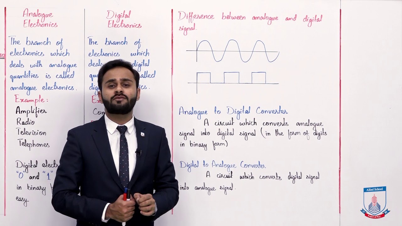
The conceptual difference between binary digital signals (HIGH/LOW) and continuous analog signals.
How standard Light Emitting Diodes (LEDs) function, including understanding polarity (anodes and cathodes).
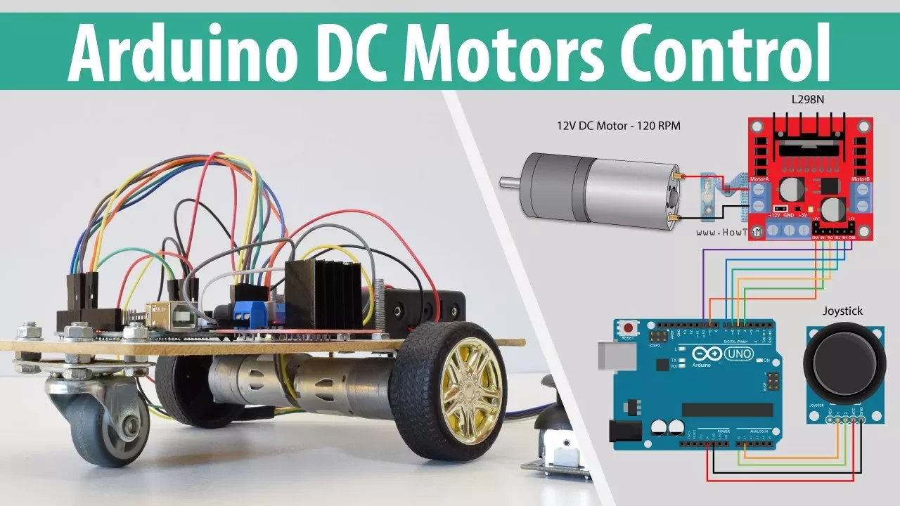
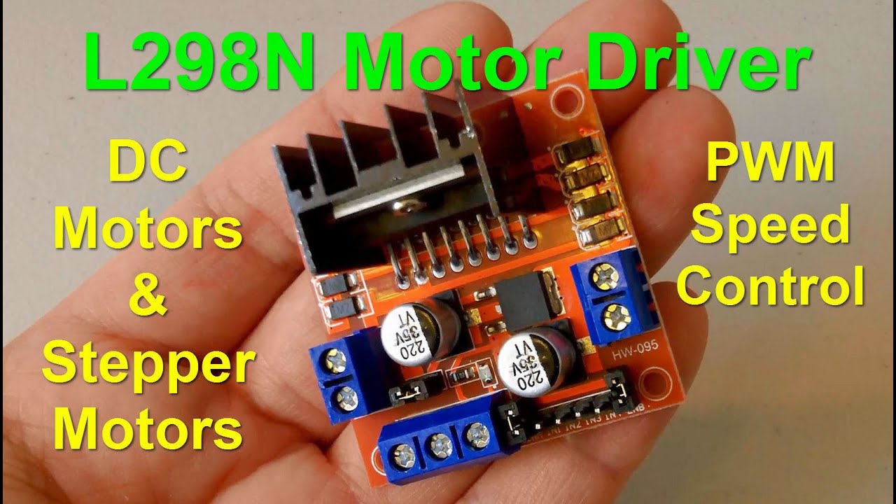
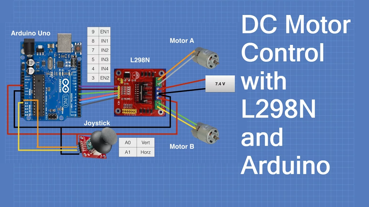
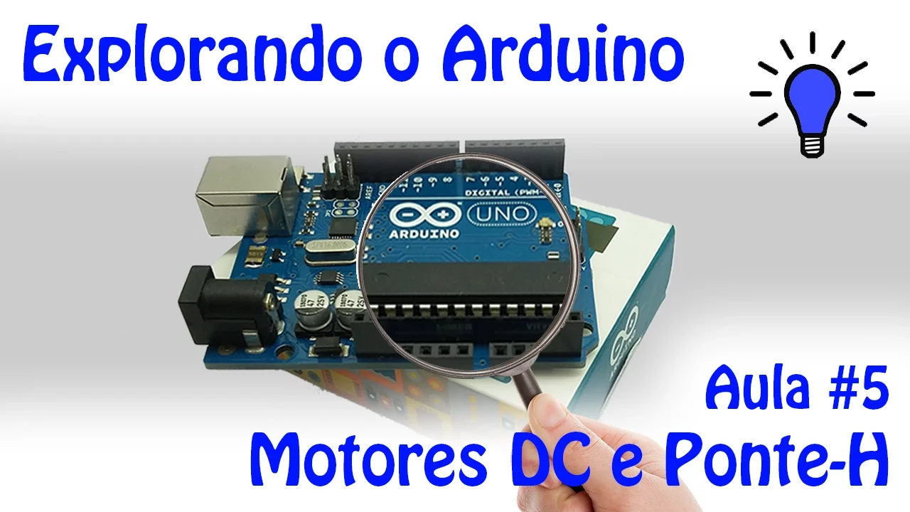
Using PWM to control the speed of DC motors using external motor drivers like the L298N H-Bridge.
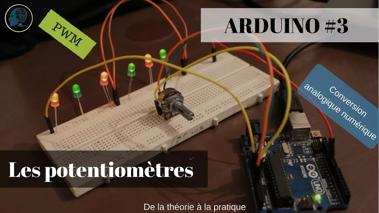
Reading analog inputs (e.g., from a potentiometer) using analogRead() and mapping those values to control PWM duty cycles.
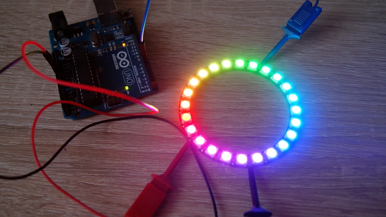
Transitioning to addressable RGB LEDs (such as NeoPixels/WS2812B) to control multiple LEDs independently using a single data pin.
Understanding hardware timers and registers in microcontrollers to configure custom PWM frequencies for advanced applications.
268 views3likes1:22:01Original Release: 2020-05-09
hello welcome back to computer aided measurement and control online class in this discussion now we are discuss about pulse width modulation or PWM in this pulse width modulation we are going to generate some kind of average voltage or we create the output voltage for later before we do discuss about the self or motor or DC motor for next lecture so I think this whose width modulation is very important for you before we are going to sample water I am the sea water so in this objective and we I just a teacher but in this topic and you can see in the chapter four of our textbook and it's about the analog analog output okay and objective in this lecture online nature is to understanding first force with modulation or PWM and also analog output using Arduino you know and learning how to deal with RGB LED in this experiment we are going to use the Arduino you know in potentiometer and this one is I've kind of edgy Blvd and maybe in your Arduino kit you have this kind of thing as UD LGB LED of the common cathode and as designed also same with the internal resistor installed in this PCB board so you just put in the cable directly and also you need to also LED of course alright we're going to next slide in this lecture our topic is analog right function in analog pride function is basically to use to set the analog voltage output value in the digital output pin only this kind of pin and this is a timer pin in three five six nine ten eleven pin for generator pulse pulse width modulation and ardena you know okay and the syntax is you just gift pin in here analog I Big W right rename the value the value is this one between 0 through 255 because it is eight bits value so the range is total is 256 so the range is between 0 to 255 so for example in here for simple calculation if you want to put the output value with the value 63 decimal value between 0 to 255 so maybe originally the voltage is about 1 2 3 5 voltage output value okay this one is very simple analogy so simple operation I think everybody can understand so in X in your textbook so there is the timer pin which is timer there are 3 timers timer 0 a time or one and timer to a special timer in time of 0 it's working with 980 Hertz and mr1 a pin 9 and 10 and also timer 2 is as equal frequency with 3:11 a for timer 2 is a timer used to generate the pulse width modulation for this rate operates a log voltage or on a local food so we are already talked about the function how to write this as similar mollify is a pin of can generate pin pulse width modulation and the number between 0 to 255 in previous slide we already discussed about it and in timer 0 this is calculation of very odd it's about 1 point 0 20 millisecond and number 1 and timer to is a double period okay so next what is actually for sweet modulation in food oh sorry is one mystic what's with modulation okay you save it okay I'm sorry so and when where we are happy post with modulation is actually the modulation technique can create digital variable with bows and these apples can represent the amplitude of analog output signal if you take it average value it will have two analog output signal originally and post reporter Lisa provides a digital output pulse waveform with a adjustable height mark period okay the high the high output state is commonly called a duty cycle understand only high output state is commonly called a duty cycle this was a very important may be only high output state we call it a duty cycle how many percent the boss offer with modulation is call it maybe can ten percent or 50 percent 60 percent something like that we call it using terminology of duty cycle it is the height output state okay this one the circle is expressed as percentage of over a period of the pulse-width before example 50 duty cycles gives an equal a space ratio of the signal okay I took this picture from your textbook as we can see this one is digital output high and low and this kind of signal maybe is using pennies okay actually your signal is like this okay so and book is I think very what could to present okay actually saw signal is like this high n low okay this I see now is called it only is a curve this one is you thin cycle I just type a DC okay duty cycle and this from here to here is call it period which is not only know the frequency for time of zero is about so you wrote 20 millisecond timer 0 and time are one - it's about double their yard something like this ok this call it a duty cycle or only high signal so you doesn't care about the law okay so in the below figure is the stage and if you have the 50% duty cycle and this is this a car if you have equal signal because in our duty Seca this one is 50% off very odd so in period and this one is half a yard with this acre 50% the output value is a HD is in the middle of the signal so you have about 2.5 sorry to 5/4 in afraid value for analog output I hope you understand I will erase this okay or max will be smart clear for you this one I just add so look from your book in the left figure is a higher type wrong every time oh sweet modulation okay I'm sorry okay this one is pulse width modulation pose or line figure as you can see this one is full high on read this one duty cycle 100% so the output voltage is originally also 5 volts this one might be 5 volts so if you use the duty cycle 8t % something like this okay this one I ate eighty percent duty cycle this one is 1:40 period okay this one one period this one is 80% of area and the that is averagely around here okay this our output voltage is athletes live around here about sixty percent is same this one is digital signal of sweet modulation percent duty cycle and it's 140 percent [Music] and this one is average voltage for 40 percent duty cycle for analog output and this one is 20 percent okay and it's really love what would voltage yeah this one zero duty sec oh nothing I think this one is not zero this one I think about five or one percent I think five percent because this has signal I [Music] think the Sun is five percent I think this is wrong I think I'm on because it's a signal if zero percent and you got up soil okay so if we observe the signal in using oscilloscope you know astroscope maybe this kind of device you have monitored here and this one is channel the Sun is many buttons here this one is a little Cirrus cop okay this one is a 10% it's a signal here now this signal is on the high and low okay so nice 20 percent duty cycle 50 percent duty cycle and this one is 40 percent duty cycle [Music] this one is 50 percent fifty second 50 half of period this one is period this one is 50% of period it is hi Sam okay charisa we call it only high on so this one is 60% okay 60% and this one is 70% like people saying like this and 90% like this this one is pulse with modulation or analog output I just stopped from look using timer 0 and this frequency and this affair is an off duty cycle and this one is period is apparently about 120 millisecond you defied it three 980 Hertz very odd okay and this one with with off this one with off on all right okay and this one maximum voltage of the I think of high voltage amplitude and frequency and this one is average value of post with modulation as we already discussed in previously the phosphate modulation if you take it average voltage it can generate the average value of analog voltage depends on duty cycles all right so we began next experiment first experiment because we I don't have oscilloscope but available so we use the Rd not to check the signal pulse width modulation signal through analog input analog 0 this one we just connected sorry we want to check the puss-puss width modulation pulse width modulation signal according to the duty cycle sorry okay we just connect this pin 11 which is the what is 11 times Mar this one time either 0 ok I'm at 0 and this one I think I am where to x re timer 1 number 2 is 11 and 3 this one is Tamar - ok you set em are more to check again reven is a timer - okay yes tomahto frequency about I'm correct 150 Hertz 490 hurt sorry yeah anyhow anyway he just connect and just see the code I hope you don't feel boring with this selector and okay so constrained by the pin WM o sweet modulation we said pin in a band okay and constant by clean analog we use analog put zero and you set V reference voltage reference as v we already studied about the analog input right for previous lecture okay in this experiment we just said how much duty cycle as the input and the serial monitor so we need to the second variable and value is analog input value so we need this variable and we want to convert to voltage this amount of voltage of course we need float variable for voltage okay in foil set up the serial game and the 600 a scissor and in the beginning we write by using analog cry we already studied this one function to generate analog output using pulse width modulation okay you set the pin 11 and we just fell use it all this and nothing zero is a zero fault we just had first zero okay it is zero post feed modulation duty cycle 0 and in for it loop first we have to read the analog input so how to how to do using analog rip and set the pin pin is 0 okay I want to change the color you see 0 okay and convert to voltage just do 5 voltage if I did that this is my value 0 and 2 3 3 4 4 10 bits for analog input ok you already learned this already studied and just print the voltage value in Syria input okay so we just measured for sweet modulation input signal using analog input is 0 you want to see what is voltage input from post width modulation output 11 and then in this function we want to set the duty cycle using serial monitor so in here if Syria available serial dot available okay check the serial monitor available for input for input okay so Secor we check the number first integer fair skinned so only number and the constrain is set the duty cycle lower is zero percent two hundred percent you just give input from zero to hundred percent and then this duty cycle convert to decimal value of 250 500 give a simple calculation to the second multi-play maximum value it assumed value up to the surgeries are not very easy and then we generate the phosphate modulation or pin 11 depends on how much a duty cycle we give input in serial monitor this one okay this only spin 11 okay I hope you don't confuse this and we said any number for duty cycle from 0 to 150 second for 90% we said in Sarah monitor ok I hope you don't confuse with this code okay so come back - okay next video first and this one uses a serial plotter and this one channel common this one is 50% and reset the value 80% in here change the duty cycle 80% something like this and 20% something like this okay using serial plotter not serial monitor Sarah plotter said 50% worse the post generation can be like this 50% period and 50% duty cycle and then type in here 20% to the second change it the value of duty cycle can check the output voltage from pin 11 okay I have the Arduino on my table okay already set everything in here [Music] okay now go to the program so where is it program [Music] this programs him in DBT okay maybe I will repeat again first is pain no matter and terrible you set this variable and Sarah communication and you first set p WM 0 first and we want to measure the pin the ribbon and blot in sorry our monitor this convert the value of all this and then we check this area monitor by giving input T 2 T second how much percentage we give it from the saddle monitor and simulate the BMW based on duty cycle okay so this one for life and you just upload this one and we have to take the cable first connect the pin 11 through a zero okay I already uploaded this one and you can see the serial plotter go to tools and serial plotter control CL okay listen is aerial plotter it's because we put the pulse width modulation first beginning is zero okay and if there any value in here see the input cuz I'm going to put the ten percent duty cycle and click send and this one is for test for ten percent duty cycle this one is 20% see I type this input and just sent Li and of course the period will increase for pi in here you can see 30% this one is 30 percent duty cycle 40% okay and it's only 50% this one is 50% we going to 60% this one's 50% 60% 70% 80% 20% and this person is 5 volts is on on monkey that is force with modulation for in the label because we don't have oscilloscope in here I just have you know itself to check the output value from being in heaven said to this echo if zero duty cycle is gift zero voltage in the Booker there is a big something like that is a thing is wrong about 5% is 5% so on this paper saying there is a signal very little see now generate for 5% okay anyway the response with modulation okay I think very easy okay this one is pulse width modulation to generate the average output voltage under using timer function in happy no no okay for next experiment we are going to fade in the LED based on the analog output signal variation okay I will end this video and I will like to beat making this video again wait a minute okay for experiment - I followed textbook page hundred server and this one we connect led on the pin 11 for timer to timer to time to connect to led a resistor of course Johan call it you call it Johan is it and we are going to fading the LED based on the output value of sweet modulation okay just simply connect to register to 11 time r2 and this one already and go to ground very simple connection so in code course this he said in MW case except in and in the textbook there is no surreal monitor but in here I use the serial monitor to check the value of output in the for loop okay so we need this to check the value of the LED so invite loop in your textbooks we are doing actually I'll put off post with modulation from 0 to 255 with increments of 5 decimal value this one is increment by 5 I plus equal 5 its meaning is the same I equal I plus plus 5 this one is equal like well algorithm so this one is both LEDs 11 set analog right and this one value i from 0 to 255 with increment by 5 I'm sorry I I plus is check the value of I when sorry up bring em to check-in ceremony toy display inside I'll monitor the value of I and delay and then he put the value P W M 0 means led off a bit annoying using her here mouse I will buy a salmon moist IV and delay one second and this one is we want to fading the LED from failure to 5 5 to 0 can hear it here 255 to 0 with increment -5 okay so I hi minus 5 in this algorithm using like this is equal C so an upright in 11 and the value of I answer er bream display that check the value of I and delay hundred okay and then after that led off or one second very simple okay I wish you understand all right can we check the video okay this one is video experiment from 0 to 255 so 2 5 5 to 0 and this one this one is a your monitor check the value decrease and then increase we can play together if we play together he's a very interesting this one is 2 by 5 and the chrysalis is more faster I record separately the video so she cannot be together okay for clearly we do life in here I have to led in here okay and this one is cot is similar in the presentation our sedation I will explain again this one is in 11 okay and in fourth setup we want to display the value of I so it set the cursor our communication is very standard in here and for it loop this one increment by 5 okay from 0 to 255 I less than 2 5 6 or you just type less than 255 is same anyway this one is a same ok so another write in LED I to the PWM signal and rye and pin number comma the number decimal between 0 to 255 okay and then sorry uh please check the value of the I what is I actually this one okay and then delay under really second and after loop you off the LED in hurry be set at BMW tell you this amount is zero no matter is no problem and this one loop 4 to 5 5 to 0 by increment minus 5 this one you can type this same like I go hi minus 5 you can type like this is is I think same our just using this anything is so nice better ok analog right anyway and I will write BNE labor this one to five five tell you from 2 by 5 to 0 and display say I wanna third delay and then after LED obtain a tiny sketch and calm [Music] upload applauding done uploading I have to chase the there is a legging and video I don't know why I think it's close this [Music] way Jonas doesn't appear a very strange very strange oh sorry very strange I'm very strange [Music] thing it's fail of my video oh very strange forgive me you and lost connection very strange I think we have to set the Wi-Fi sorry why Varys why my wife I'm sorry for your waiting I should be using Wi-Fi okay nice connected try again really are you kidding me device IP is same are you kidding me okay I will come after it I saw this with you guys I already solved this problem so now in experiment to explain again this one is spin 11 okay and this program is similar with intubating I already explained and just upload this one and this one is experimental set up an IDE X on my desk and you can see the radio already blinking at the same same program ok it's done uploading so you can see the LED is change the value based on the PWM signal and going to reduce the light can see in off the light you can see the clearly the LED become more brighter and off n come reduce the line something like that anyway you understand I think okay forgive me about that is my connection it's not very good anyway this experiment - I think you can practice in your home using this program this program is basically I change the value of a PWM from 0 to 255 by increment 5 and print the serial monitor ok and off our Reedy on one second and this one change the value from 255 to zero and ready off and I think it's better if without led off the thing is more beautiful can upload and then uploading you can see this area monitor the fabulous increase as I turn off the light you can see the LEDs [Music] decrease the light and increase again like this maybe the delays can change this delay maybe five hundred thirty second a flat again see the LED more brighter much lower then decrease the the number of BMW or these are increased now still increase view so in its maximum and then decrease the number so the light come more low intensity see the know of something like that I hope you understand this experiment think this on if I plot again with delay more lower delay and see the LED or faster bright this and lower brightness something like that okay okay now going to next experiment just leave it this okay this one is the video you already watch it so going to next so next experiment still in experiment 2 but at this time we are going to add the potentiometer in here for channel a 0 in here the schematic diagram is similar from the textbooks page 108 so the code is think I things little bit to check the value of the what value variable so we check the setup begin ok first the pin value in analog is 0 and I you also know pin LED for timer to pin 11 and then if I setup serial communications header begin and the 604 it loop we read the analog read in a 0 this one in analog a 0 okay and I love read or the value in integer value variable okay this one confession to tell you thousand twenty three two two five five maximum okay [Music] in this case the analog breathe is 0 2 1 2 3 because it's 10 bits okay we want to point 4 0 2 2 5 5 so using this equation value out and then for another write in led 11 okay I'll trade you based on the calculation or value and then we display the value and then delay okay I think it's no problem with this so this one is video we check it when we rotate the Redeem all right okay this one is the value of the output variable so changing does maximum two by five and then decrease when we rotate potentiometer counterclockwise setting okay so we have same program here standby in analogue zero and we have in here my desk and it is the uh-huh because the Spearfish program [Music] okay this on the same serie begin consider communication and infinite loop we read the analog v4 potentiometer it's one button see you then analog a zero this one say and the value should be conferred we have to convert to in range zero to 255 so using this equation alright and then I generate the MW PWM sorry loss with modulation based on this tell you from range 0 to 255 so we just check the value in here and display answer our monitor and then delay all right so we just upload load and program now we can you can rotate the potentiometer maybe the light is on it's my finger this one is I'm sorry we have to put the cable what potentiometer coming to a zero so when we we rotate this we do with more intensity more because the value is increased I'm sorry displayed so this one is now maximum value because the potentiometer if the value thousand twenty three so we can reduce the value okay maybe life is Oh the same tightness Leifer like this thing is better like this okay see the intensity of LED changing when I rotate the potentiometer okay can you get it because the it depends on the value of force with modulation duty cycle all right okay this experiment I think very easy for you you can practice and so a home okay that one is experiment to the thing you have if you have any question you can ask me in contact all right okay you watch video again when we rotate this one LED you become more lightness okay so now we are going to work in FDD red green blue LED in red green blue LED is fundamentally a LED package which consists of red green and blue LED is a two type kind of led @gb LGB led Emmy first is common anode or c'mon cathode which is a ground is in here and common anode is positive in this schematic there is no internal resistor so you need you should install the resistor together with this pin all right okay if this is a three internal color LED are combined we can create a combination of color all right in this picture I took from the this link you can click this tree and it can read what is actually our RGB LED okay it's basically it consists of red and green and blue LED and this early B we drive using pulse width modulation signal and change the intensity of the light of the treat of LED okay and this one is packaged in your adrenal kit this one is GB you can find you can find in your and iñaki we then built with the built-in resistor on the PCB and to generate color you just activate the for example in here right yes give it value the M PWM for right two five five maximum and green in for the middle because of course this is red green blue and green green is in the middle and red this pin first in here so defeat this two five five first all red and green middle and blue for the last okay for science called combination between green and blue so this drill and blue combination will give new color cyan and magenta color with red and blue okay and yellow red with green if both at that all activated if the color of white this one is hexadecimal value you can activate also using hexadecimal value but I think is more easy using decimal value by five two five five okay is nothing very easy okay this one is chaotic of a GB led come on cut out I am right I think right common cut oh so you just connect in this in the ground for negative okay so in experiment third third experiment Facebook page and the ten hundred eleven is the same the GB led red green blue negative it's connected brown for writers connect in 11 green connect in time remember this one is timer I'm not - this one is time not one okay number one all right this one a schematic in the event then nine red green blue this one is a DVD okay thing is no problem with you let's connect directly with the cable because this already built-in resistor so you don't worry about this but there is kind of to be led with out the sister is a you should connect with resistor otherwise you destroy your LED okay so in this case we already have let's start in with in GB already so you just put in directly with the cable all right in textbooks we drive a different color color it green I'm sorry this one is blue so a nice blue and don't update this program copy paste so I think sorry [Music] alright the cycle baked so in your textbooks there our function we call it set RGB but in textbook is empty so you should write this and I look right or in our level and based on the value of our and yet whatever input these are you should put it and analog right in G and value of G and enough right pin be in nine value of blue be this one there are three value of G be okay the first is only pin same thing and fight set a DB function to 1 and G be led and for it loop I'm sorry fight setup I think we don't need this addition is not necessary to put set the output it's also working but if you put the output tell you or in mode also working so I think you can delete this function is there not necessary and in for loop first is activated 2 5 5 4 here and delay one second and set RGB for green in the middle 255 and delay one second set RGB for blue delay one second and in the textbooks LED off but in this experiment I delete this function this one not necessary I think miss it's not beautiful when you set off the ad LED I don't know I don't like this so I delete it so the science color cyan combination between green and blue in this magenta red and what is this blue and this one is yellow red and green and white color all is on okay after that there is a for loop we drive the change the value from red first when I is zero we start from red and then changing the middle color so from red variation to green okay because this will increase this one this one becomes zero and this only come the final result is like this first result is two five five zero zero okay and then bill a hundred this one incremented by five okay for loop for loop we try from green to blue we start from zero to five five first and then go to two to five okay because this one - I so will be decreased by 5 and this one will increase until to five five so this one is final result design is first result this will be like this okay I think this one using red is not good and for third loop we going to from blue to add the first begin from zero zero two five five until the failure changing to five five zero zero okay in the textbook stopping delay 20 I change it hundred inhale two more slower and in textbooks use Reedy off but I delayed this function I think not necessary so go to the video I hope you understand for loop I think it's very easy this one I explained from first red to green and green to blue or some blue to red just like that okay liking I think we can delete this I think okay so this one is video see cyan magenta and yellow white and then change red to green from green to blue from blue to red and then repeat again red green blue cyan magenta yellow like that okay this one is final experiment from this class so I hope you understand for LGB already okay so in here I already astir RGB LED this kind of bi so change the cable furs and is this one is similar in BBT first it's a pain of course and there is function called it set RGB based on the value of red green and blue okay from 0 to 255 I see user and then you suit an unlocked right in here in red the value of our so this one is should be like this - Alice red and this one is green do I wish you understand okay I'll enter this on and infinite set up I think this one is not necessary I think this one if you use another up right it's always output so you don't need this set output for pin another if you use analog right you don't need set the output because is known as output so no need okay in for it loop red green from program from Midas copy from fragra okay this is white cyan magenta yellow light and this one this one program from red to green this one from green to blue Sun from blue to red and last one in textbook always off the originating this is not necessary I delete this you can do in your home if you can try and okay upload this program uploading comparing sky uploading so you can see the GP ID now is on by changing the color and color is changing and you see now with all of the light is very can see the RGB LED changing the color from green blue cyan magenta yellow white and changed red to green and then green to blue something like that okay I think you see my explanation if in my explanation not clear you can have question monitor okay so go back to PPT the sign is video I mean go back to program first this put the input value and set RGB set up for it Lou okay no matter for you okay now homework I make it easy I don't want to your life become more difficult so this work is I basically similar in text book age and read 12 okay if you have a different book I think I think is same I wish the same anyway you have to control the pulse width modulation value using potentiometer and to control the RGB value LED in this case in fact force width modulation fairview less than equal under 28 use combination color and and green okay and more than hundred twenty eight combination color green to blue this only spin assignment inside - you can use analog any analog pin for potentiometer and algebra-ready using similar pin 11 and 9 and Brown is basically this one so I don't have any comment for this program anyway if the value equal less than 128 the combination color is red and green I think use this equation and I think for if this one I think is not necessary I think you can delete this Sun is rubbish because this one is cannot be negative fairly well and why they said this less than zero and cannot be more than 255 because you already declare in here the value is maximum 255 so I think on it also this one is not it this one is but if you want to put in a soft fine but I think knowledge all right so there is no question I think because this similar in textbooks 800 [Music] and this one is video if we wrote it so the color from red to green rotate more from green to blue something like that right and if you go back blue to green and green to red okay very easy right I hope you understand for be some work is I think very easy same learning from textbooks okay thank you for your attention for attending this class and I wish you have a good day have a good day and thank you very much
Up Next

3:01
PID Tuning for Self-Balancing Robots: A Practical Guide
@RobusTwoMinuteTutorials
354 views•2025-12-23

12:54
Triumph of Orthodoxy Icon: Byzantine Art & History Explained
@BenCallan
2.1K views•2024-08-06

9:49
FastAPI vs Flask vs Django: Choosing the Right Python Web Framework
@TechWithTim
302.5K views•2024-05-26

1:42
Game of Thrones Opening Credits: A Cinematic Analysis
@gameofthrones
46.3M views•2011-04-18
Related Study Plans & Knowledge Roadmaps
Structured learning paths in General & Interdisciplinary Studies
general-studies
Elevator Engineering: History, Physics & Cities
01From Hoists to Safety Brakes: The Dawn of Vertical Lift
02Hydraulic vs. Traction: The Engineering Physics of Elevators
03Modern Speed, Safety, and Algorithms
+ 2 more learning modules
12h5 modules
Explore Roadmap
general-studies
Rubber: Material Science, History & Geopolitics
01Origins of Natural Rubber & Mesoamerican History
02The Chemistry of Natural Rubber & Vulcanization
03The Geopolitics of the Rubber Boom & Colonization
+ 2 more learning modules
12h5 modules
Explore Roadmap
general-studies
Containerization: Evolution, Logistics & Trade
01Ancient Trade & Bulk Cargo: Amphorae to Barrels
02The Industrial Revolution & Cardboard Packaging
03The Containerization Revolution: Malcom McLean
+ 2 more learning modules
12h5 modules
Explore Roadmap
general-studies
Textile Tech: Evolution, Labor & Global Impact
01Pre-Industrial Textiles: Handloom & Cottage Industry
02Mechanization: The Spinning Jenny to the Power Loom
03The Factory System & Global Labor Transformation
+ 2 more learning modules
10h5 modules
Explore Roadmap