









![LAZO ABIERTO y LAZO CERRADO ✅ [Sistemas de CONTROL] #009](https://i.ytimg.com/vi_webp/CxGFoeJ7SD8/maxresdefault.webp)




The L298n dual H-bridge motor driver is a versatile module that controls two DC motors (up to 2A each) or one stepper motor using TTL signals; it features a 5V regulator with a jumper for power supply management (7-12V with jumper enabled, >12V requires external 5V), where direction is controlled by IN1-IN4 inputs (high for forward, low for reverse) and speed via PWM when enable jumpers are removed, while stepper motors require specific pulse sequences (e.g., 1-3-2-4 for clockwise, reversed for counterclockwise) applied to the phase connectors.
L298N Dual H-Bridge Motor Driver for DC and Stepper Motors
Added:Fundamentals of DC Motors: Understanding how voltage and current drive rotational force, and how reversing polarity changes direction.
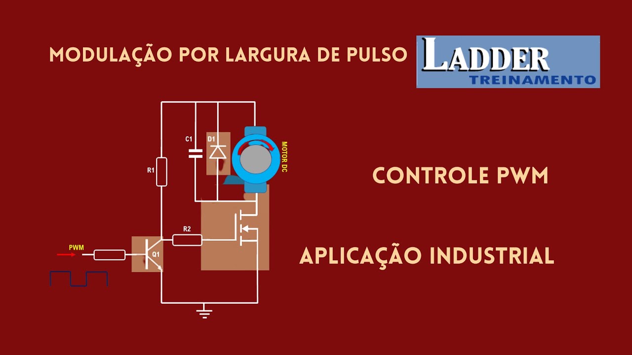
Pulse Width Modulation (PWM) Theory: How duty cycle adjustments regulate average power delivery to control the speed of an electronic device.
Basic Microcontroller Programming: Familiarity with GPIO configuration, digital write commands, and analog/PWM output (e.g., using Arduino).
Basic Circuit Principles: Understanding common ground requirements, external power sourcing, and the difference between logic voltage and motor driving voltage.
Transition to Modern Motor Drivers: Exploring more efficient MOSFET-based drivers (such as the TB6612FNG, A4988, or DRV8825) to reduce power dissipation and heat generation.
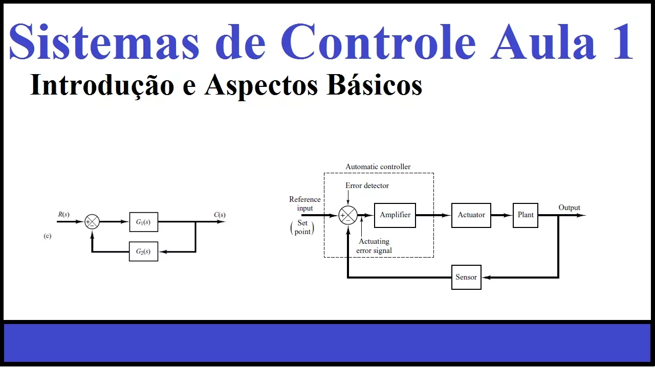
Closed-Loop Control Systems: Implementing feedback mechanisms (like rotary encoders and PID control algorithms) to achieve precise speed and position control.
Electrical Isolation and Protection: Learning about optocouplers, flyback diodes, and transient voltage suppression to protect microcontrollers from inductive spikes.
Robotic Kinematics: Applying dual motor control to build differential-drive mobile robots, incorporating path planning and obstacle avoidance.
207.2K views2.5Klikes9:46Original Release: 2020-05-09
this is the l-29 t8n dual h-bridge motor driver this is a very versatile module that gives you control of DC motors and stepper motors with this module you can control the direction and speed of 2 DC motors up to 2 amps each or one stepper motor these are very inexpensive modules that cost about $3 apiece and you can find them on eBay Amazon or other online stores in this video I'll show you how to drive 2 DC motors to control the direction and speed and I'll show you how to control a stepper motor as well this is motor a connector and this is motor B connector to control 2 DC motors you connect one motor to the motor a connector and the other motor to motor B connector the polarity is not necessarily important to control a stepper motor you need to connect one phase to motor a and another phase to motor B connector you can use a unipolar or bipolar stepper motor these are the power connections you have the power supply input ground and 5 volt input or output this means it can either be 5 volt output or 5 volt input depending on how the module is powered the power supply input range is about 5 volts to 35 volts DC if your power supply is 7 to 12 volts DC leave this jumper in place this jumper connects the power supply voltage to the onboard 5 volt regulator to power the board if the power supply voltage is greater than 12 volts then you should remove the jumper the voltage regulator can only handle up to 12 volts from what I understand if you remove the jumper you will need to power the board with 5 volts at the 5 volt connector if the power supply voltage is 7 to 12 volts then this connection is a 5 volt output instead of an input when the jumper is in place you can use the 5 volts to power your Arduino your pic microcontroller or other devices depending on the power consumption this section is where you control the motors or stepper motor all these inputs are controlled by TTL signals there's specific ranges for TTL voltages but to make this simple zero voltage is low and five volts is high this jumper enables output motor a and this jumper enables output motor B if you are controlling two DC motors and you want control of the speed of those motors you need to remove the two jumpers and provide a variable PWM signal to these two pins with the jumpers in place the motors will have full power or one hundred percent duty cycle in one and in two controls the direction for motor a by applying a high signal or 5 volts to n1r into one of these pins will cause the motor to go forward and the other in reverse the same goes for in three and in for these inputs control motor B depending on which way you connected the motor it will determine which input drives foreign or reverse okay I connected two DC motors to the L 298 and module if you notice the white wire that is feeding into the power supply input that is five volts and since 5 volts cannot turn on the onboard 5 volt regulator I also need to feed 5 volts into the 5 volt input which is the yellow wire the green wire is ground also have 5 volts here then I'm going to connect to in 1 2 in 4 and that will control the motors in 1 and n 2 will control the left motor and in 3 and n 4 will control the right motor note that the 5 volts I have here and the 5 volts on the white wire and the 5 volts on the yellow wire they all share the same ground [Music] two DC motors and I'm using a microcontroller which is the one right there like I mentioned before to control a stepper motor you need to connect one phase to motor a connector and the other phase to motor B connector note that there is easier and more efficient driver boards out there for controlling stepper motors for driving a stepper motor make sure it enable a and enable B jumpers are in place I created this push-button circuit to help me figure out the sequence of pulses that I need to feed into the in wante and for this orange wire is connected to positive 5 volts and when I press one of these buttons it'll feed 5 volts into the corresponding input once you figure out the sequence to move the stepper motor in one direction you just need to reverse the sequence to move it in the other direction okay I have my push-button circuit here to help me figure out the sequence for driving this stepper motor first of all I have two of the phases connected to the driver board one phase is connected to motor a connector and another phase of the stepper motor is connected to motor B connector I also have 12 volts coming into the power supply input as well as ground the five volts is actually an output now so I can take five volts out of that connector if I wanted to so after playing around with the push buttons I figured out that one of the sequences is 1 3 2 4 1 3 2 4 1 3 2 4 1 3 2 4 and that actually moves the stepper motor clockwise so I can just add pulses to the in 1 2 in 4 inputs to drive a stepper motor forward if I wanted to drive the stepper motor counterclockwise I would reverse that sequence and that would be for 2 3 1 4 2 3 1 4 2 3 1 4 2 3 1 4 2 3 1 and that's the sequence for driving the stepper motor in a counterclockwise direction I am going to drive a stepper motor it's a NEMA 17 and here's the pic microcontroller you can forget everything else around it okay I connected a different stepper motor to the motor driver this one happens to be a PM 4 2 - 2 - 2 0 9 so one thing I had to do was modify my code so it can do one revolution clockwise and counter clockwise I'm using the same microcontroller so if you need to control a couple of DC motors or even a stepper motor the L 298 and dual h-bridge motor driver is an option thanks for watching my video please like and subscribe to see my future videos have a great day
Up Next
19:07
BB-8 Droid Build V3: Flywheel & Head Rotation Testing
@jamesbruton
83.1K views•2016-04-08

12:54
Triumph of Orthodoxy Icon: Byzantine Art & History Explained
@BenCallan
2.1K views•2024-08-06

9:49
FastAPI vs Flask vs Django: Choosing the Right Python Web Framework
@TechWithTim
302.5K views•2024-05-26

1:42
Game of Thrones Opening Credits: A Cinematic Analysis
@gameofthrones
46.3M views•2011-04-18
Related Study Plans & Knowledge Roadmaps
Structured learning paths in General & Interdisciplinary Studies
general-studies
Elevator Engineering: History, Physics & Cities
01From Hoists to Safety Brakes: The Dawn of Vertical Lift
02Hydraulic vs. Traction: The Engineering Physics of Elevators
03Modern Speed, Safety, and Algorithms
+ 2 more learning modules
12h5 modules
Explore Roadmap
general-studies
Rubber: Material Science, History & Geopolitics
01Origins of Natural Rubber & Mesoamerican History
02The Chemistry of Natural Rubber & Vulcanization
03The Geopolitics of the Rubber Boom & Colonization
+ 2 more learning modules
12h5 modules
Explore Roadmap
general-studies
Containerization: Evolution, Logistics & Trade
01Ancient Trade & Bulk Cargo: Amphorae to Barrels
02The Industrial Revolution & Cardboard Packaging
03The Containerization Revolution: Malcom McLean
+ 2 more learning modules
12h5 modules
Explore Roadmap
general-studies
Textile Tech: Evolution, Labor & Global Impact
01Pre-Industrial Textiles: Handloom & Cottage Industry
02Mechanization: The Spinning Jenny to the Power Loom
03The Factory System & Global Labor Transformation
+ 2 more learning modules
10h5 modules
Explore Roadmap