
![#2 Instrucciones Básica [ pinMode, digitalWrite, delay ] - Curso Arduino 💻](https://i.ytimg.com/vi/dwet3or5rmQ/maxresdefault.jpg)









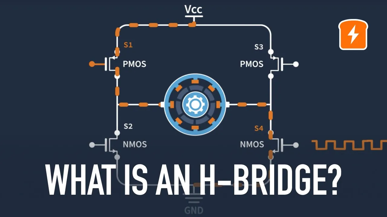


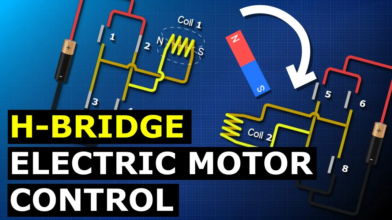




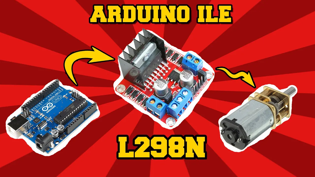









The L298N H-bridge motor controller is an inexpensive module that enables bidirectional control of DC motors using an Arduino by utilizing four switches arranged in an H-configuration to reverse polarity and Pulse Width Modulation (PWM) on enable lines to control motor speed; the module accepts motor power (5-35V), a 5V logic supply, and four digital inputs for direction control, allowing hobbyists to build projects like joystick-controlled robot cars.
Control DC Motors with L298N H-Bridge & Arduino Tutorial
Added:Basic Arduino Programming: Familiarity with the Arduino IDE, writing standard sketches (setup and loop functions), and configuring GPIO pins.
Pulse Width Modulation (PWM): Understanding how duty cycles are used to simulate analog voltage variations for controlling motor speed.
DC Motor Principles & Electrical Constraints: Comprehension of how DC motors operate and why microcontrollers cannot directly supply the current needed to drive them.
H-Bridge Fundamentals: The theoretical concept of using a network of switches to reverse current flow polarity and control motor direction.
Closed-Loop Feedback Systems: Integrating rotary encoders and implementing PID (Proportional-Integral-Derivative) algorithms for precise motor speed and position control.
Advanced Motor Drivers: Graduating to modern, high-efficiency MOSFET-based motor drivers (e.g., TB6612FNG or DRV8833) to minimize voltage drop and thermal losses.
Wireless Teleoperation: Replacing the physical joystick with wireless communication interfaces, such as Bluetooth (HC-05), Wi-Fi (ESP32), or RF modules.
Autonomous Robotics & Sensor Fusion: Implementing obstacle-avoidance or line-following algorithms using ultrasonic, infrared, and Inertial Measurement Unit (IMU) sensors.
1.4M views19.8Klikes36:41Original Release: 2017-03-11
today we'll be working with the l298n h-bridge motor driver you'll learn what an h-bridge is and how to use the inexpensive l298n module with an Arduino to control the speed and direction of a pair of DC motors we'll even build a simple robot car that you can control using a joystick so stay tuned and welcome to the workshop [Music] hey welcome to the workshop today we're going to be working with DC motors and we're going to be controlling them with a component called an l298 NH Bridge we're going to look at how DC motors actually work and even a tiny bit of the history of them because I think that stuff's interesting then after that we'll discuss what an H bridge is if you're not sure of that once we do that we'll exam in the l298n the l298n is a really common H Bridge module that you can use on its own or with an Arduino and we're going to be doing both after we do a couple of experiments with it we're going to actually do something amusing and build a little robot car that we can control with a joystick using an Arduino and an l298n so let's get at it let's take a look at DC motors DC motors are Motors that operate on direct current as opposed to motors which operate on alternating current the first motor was invented by a Hungarian physicist named anos jedlick in 1827 and he called his device an electromagnetic self rotor interestingly enough the self RoR that you see pictured here was constructed in 1827 by jedlick and today can be found in the museum of Applied arts in Budapest and the device is still working working 190 years after he constructed it now the self rotor wasn't a particularly practical motor the first practical motor was invented in 1832 by a British scientist named William sturgeon DC motors are available in several different configurations from tiny little Motors to absolutely huge ones small DC motors are very inexpensive and therefore these are ideal for hobbyists just like us for all of our little Contraptions we can use DC motors to construct robot bases they can be used to create quadcopters they're also often used in model planes and boats and a myriad of other applications so how exactly does a DC motor work well here you'll see a diagram of a very simple DC motor the shaft of the motor the part that does the rotating is referred to as an Armature and on the Armature you will see a couple of coils of wire these coils are connected to the commutator that's that little copper ring at the very front of the Armature that you see the connections to the commutator are called the brush es where the positive and negative voltage are applied on the outside of the motor you'll see a couple of permanent magnets arranged in opposite magnetic polarity now when DC current is applied to the commutator it sets up a magnetic field inside the coils the coil magnets interact with the permanent magnets causing the Armature to rotate now as the Armature rotates the polarity is continually r reversed causing the magnetic field to be reversed and the rotation to continue this type of a motor is referred to as a brushed motor as opposed to a brushless motor and this is the type of a motor that we will be experimenting with today so let's take a look at how an H Bridge actually works in order to simplify things I've drawn an H Bridge using four switches in real life the switches would probably be replaced with transistors although you could build an H Bridge of switches if you really wanted to now why is this thing called an H Bridge well if you look you can distinctly see a letter H in the configuration with a motor sitting in the bridge part of the letter H thus the term H Bridge so how does this all work well you have a positive voltage applied to the top of the HB circuit and a negative voltage applied to the Bottom now watch what happens when we connect these two switches the positive is applied to one side the motor and the negative to the other side and in this case our motor will spin clockwise now let's take a look at what happens when we close the other two switches you will see that a negative voltage is now applied to the one side of the motor and a positive to the opposite side causing our motor to spin counterclockwise this is how an H Bridge functions now there are a couple of different styles of l298 and modules that you'll run across and I wanted to show you the differences between them they work exactly the same and you can use either of them in the experiments that we'll be doing but I just didn't want anyone to get confused if their module didn't look like the one that I was using so here's the one that I'm using and you'll see all of the digital inputs with the enables on either side of this connector here is another common module and here are the digital inputs the enables are actually here and they're jumpered so they're always enabled but you can just pull those jumpers and use them exactly in the same way there's also a 5vt jumper which I've got off on my module it's over here the 5volt jumper on this common module is over here then the motor connections the two green connections on this module are motor a and motor B you will find two connections on this module for motor a and motor B and finally the connection to the 5 Vols the 12 VTS and the ground are all done in the middle of this module here whereas on this module you'll find those same three connections on this connector so otherwise these modules are identical and you can use either one for these experiments and they'll work perfectly fine let's take a close look at the l298n module now the module that you have may be physically different than the one that I'm showing here with the connectors in a different position but they'll be labeled the same and they'll function identically now first we'll look at the power connections there's an input for the motor power which can be anywhere from 5 to 35 volts there's also a common ground which is common to all power supplies then there's a 5vt input now this 5vt is to drive the logic circuitry on the board and it's actually optional it's possible to use the motor power to also Supply the f 5 Vols after that we have two connections for our motors motor a and motor B now here's the jumper that we use to select whether we're using the optional 5vt Supply or whether we are using the internal one in this illustration you can see that the jumper is open I've just got it hanging there so we are using the optional 5 volts input in the way I've shown it after that we have the logic inputs to the controller there three logic inputs for motor a the enable line input one and input two and then motor B has the similar connections enable input three and input four now here's how the inputs work I'll show you motor a motor a is enable line when set the 5 volts enables the motor when it is grounded or set the logic zero the motor is disabled it can also be fed pulse width modulation signals and this can control the speed of the motor and we'll talk about pwm in a few minutes now motor A's input one and input two work as follows if you apply 5 volts to input one and ground to input two the motor will spin in a forward direction if you reverse that and apply ground to input one and 5 volts to input two the motors will run in reverse and of course the motor be inputs work in exactly the same way now pulse width modulation may sound like a complicated technical subject but when it comes to controlling Motors it's actually pretty easy to understand we simply send a series of pulses to the enable line on our motor The Wider the pulses the faster the motor will spin so for example if we send a series of short little pulses to the motor the motor will spin slowly if we increase the width a bit the motor will spin faster increase the pulse width a bit more and the motor will spin even faster if we want to bring the motor to a stop we'll just stop sending pulses and hold the enable line low this will disable the motor if on the other hand we want the motor to run at full speed we'll stop pulsing it and hold that line high and this will cause the motor to be enabled constantly and spin at full speed in order to show you how the l298 works I've set up a little experiment on my workbench what I've done is I've taken my l298 I've removed the 5V jumper so that I can power this with an external Supply I've connected a power supply to it what I've done is I've used a little Buck converter that has reduced my 12vt power supply down to 7.4 volts now you might be wondering why 7.4 volts well the reason for that is is that the two transistors that act as switches in the l298 are each going to have a voltage drop of 7 of a volt so what I need to do is apply 1.4 volts more than my Motors actually require and since these are 6vt Motors I've given it 7.4 volts in addition to the 7.4 volts I've attached a 5V power supply and I'm just using my bench supply for that for now I've attached two Mot Motors to it motor a and motor B and I've also run the 5 volts over to my selus breadboard at this point I've then taken all of the inputs from the l298 and wired them up to the breadboard so that I can experiment with the inputs and send them to either ground or 5 volts okay for the first experiment this is how I've wired the inputs I've set an able one to 5 Vols which is a high input number one is also at 5 volts and input number two is at Ground these are the lines that control motor number a for motor B I've taken input number three and set it to 5 volts input number four has been grounded and the nabal number two has also been grounded so when I do this what will happen is that motor a will move forward motor B however won't move at all and that is because its enable line is set to ground and you can see that as follows okay for the second experiment I'm going to take enable 2 which controls motor B and I'm going to move it high as well in this case both of our Motors will move forward next I'm going to reverse the inputs for motor number a so I'm going to take input number one and ground it and input number two and bring it to 5 Vols this will cause motor a to run in reverse while motor B still runs in the forward Direction [Music] and last but not least I've taken both of the enable lines and grounded them so enable number one is grounded and so is enable number two in this configuration both Motors will simply be off and as you can see they are so now that we've shown how the l298 works with a breadboard let's add an Arduino to the equation and see how we can get it to control the speed of the motor as well as the direction so let's bring in Arduino into the picture I've taken away the 5vt power supply and I've used the 5 volts in ground from the Arduino Uno to power the l298n logic circuits I've hooked the inputs of the l298 n to a series of the digital outputs in the Arduino and the hookup is as follows I've taken the enable one line on the l298 and connected it to digital output pin 9 on the Arduino input one on the l298 is connected to digital output pin 8 input two is connected to Output pin 7 input three to Output pin five input four to Output pin 4 and the enabled to line on the l298 is connected to the arduino's digital output pin 3 again you could use different output pins on the Arduino if you're willing to modify the sketch but just keep in mind that both of the enable lines need to be connected to a digital output pin that is capable of pulse width modulation so let's look at our Arduino sketch to do our motor demo now we're going to start off by by declaring a number of integers uh for motor a and for motor B and these are just the inputs to the l298n the en and ENB are the enable lines for Motors a and motor B and then I in1 I in 2 in3 and I in4 are simply inputs 1 2 3 and four to the board now again you could use different PIN numbers if you wish by just defining different numbers for these integers how however keep in mind that enable a and enable B have to use pins that are capable of pulsewidth modulation pins 9 and pin 3 are capable of pwm so if you're changing this keep that in mind after we've defined these integers we're going to just go through the setup routine and set all of them up as outputs because all of these are outputs from the Arduino because we're feeding these into the l298 NS then we're going to start with one of two functions our first function is called demo one and demo one will run the motors in both directions at a fixed speed so the first thing we're going to do is we're going to turn on motor number a with the input one and input two lines then we're going to set the speed of motor a we're going to be using the analog right command now analog right will write pulsewidth modulation signals out to pwm enabled pins on the Arduino and it can have a range of zero which is basically off to 255 which is full speed we're going to set these to analog right to 200 so it's going to be near full speed but not quite and then we're going to do the same thing for motor B we're going to set it on in One Direction and we're going to set it to also do an analog right of 200 now we're going to run the motors at that speed for 2 seconds so we put a delay of 2,000 milliseconds in here and then we're going to change the motor directions so we're going to take inputs 1 2 3 and four and set them to reverse the motor so we do that over here and then the motor will continue to run at the speed of 200 because the analog right is still 200 we do that for 2 seconds and then we're going to turn the motors off by setting inputs one 2 3 and four all to a value of low and that's basically our first demo now we have a function for demo number two and what this is going to do is it's going to run the motors across all the range of possible speeds it's going to run it up to the full speed and then run it down to low speed so first of all we're going to go and set the motors on again in the forward Direction so we set inputs 1 2 3 and four accordingly and then we're going to take a loop and accelerate it from zero to maximum speed now in this loop we're going to take um an integer we call I and we're going to Loop it between the values of 0 and 255 and so we're going to do an analog right to enable a and enable B it's going to start off with these values being zero and then we're going to delay it for 20 milliseconds then it's going to increment it and the values will be one it'll delay for 20 milliseconds etc etc all the way until it gets up to 255 once we do that we're going to do the opposite thing we're going to run a loop except we're going to decrement it so this is the same thing except we're starting at a value of 255 we're working our way down to a value of zero and we're decrementing the loop and so again we're going to start off with an analog rate of 255 to each of the motors delay by 20 milliseconds and then go to 254 delay by 20 milliseconds Etc until we get down to zero and then finally we're going to write digital wrs to all of the pins low again to turn off the motors and so now that we've defined our two functions in the loop all we simply do is we run demo one and then we delay it for a second and then we run demo 2 delay it for another second and then the loop repeats itself infinitely so this is basically our motor demo so let's take a look at it working all right I've loaded the motor control sketch onto my Arduino and I've temporarily unplugged the USB cable from the Arduino because this sketch will start immediately as soon as the Arduino is powered up otherwise everything's connected up I've got my power supply connected to the l298n board the motors are connected to it as well and the board is connected to the Arduino so as soon as I power this it should start our demo sketch so let's take a look at that [Music] and it runs through it you see It'll repeat it it starts by going forward and it goes backwards and then it gradually comes up to speed and then it gradually reduces speed and so that's our demo step now let's expand upon our circuit and connect a couple of potentiometers or variable resistors up to the Arduino Uno this will allow us to manually control the speed of each motor now the value of each of these potentiometers is not particularly important as long as they are 10K or higher they should work you also want want to get linear taper potentiometers and these are the most common type anyway now one end of each pot is connected to the ground and the other end of it connected to 5 Vols in my hookup I used a stus breadboard to simplify the connections although that isn't Illustrated here the wiper of each pot is connected to one of the analog inputs on the Arduino and I connected pot a to analog input zero and pot B to analog input one again if you wish to use different analog inputs that would be fine you'll just need to modify the sketch accordingly so now that we've hooked the two potentiometers up to our Arduino let's take a look at the sketch that we're going to be using now our sketch starts off in the same way as the last sketch we Define a number of integers for the output pins on the Arduino that we're using as inputs of the l298n and we've got a couple of new integers over here speed control 1 and speed control 2 and these are defined as a0 and A1 these represent the analog inputs in the Arduino now if you wanted to use two of the other analog input pins just change the value of a0 and A1 and you can do that now we have another couple of integers we've defined and these are motor speed 1 and motor speed 2 which represents the speeds of the two different Motors we'll initialize these with a value of zero then we go into the setup which is identical to the last program we set all of the digital outputs and Define them as outputs we don't need to set the analog inputs up as inputs because by Nature they're already inputs then everything is happening in the loop we'll set the motors to a forward Direction by writing to the in1 in2 in3 and in4 pins and then we're going to read the values from the potentiometers using the analog read command now the analog read function uses the internal analog to digital converter that's built into the Arduino this is a 10bit analog to digital converter so we're going to get values from 0 to 1,23 now if you recall when we do an analog right to to send pulsewidth modulation out to our enable lines we can take a value from 0 to 255 so we've got to convert this range of 0 to 1023 to a range of 0 to 255 and there's a couple of ways we could have done this one way would have simply been to divide these values by four and that would have actually work just fine but I chose to use arduino's map function and if you haven't used the map function before it's a good function to get familiar with what map does is it takes one range in our case 0 to 10 23 and Maps it out to another range of 0 to 255 this really works well when you have two ranges that don't evenly divide into each other and so I've set motor speed to be mapped to a value of 0 to 255 and then the last thing I do here is I have found that the motors actually started to buzz when I got to a very very low value and so what I've done is I've simply included these if statements and in the if statements I say that if the motor speed is anything less than 8 then we'll just call it a zero because the motors aren't moving down at that speed anyway they're just making an annoying buzzing sound you may want to adjust this value of eight to suit your own particular Motors and then finally we do an analog right of motor speed to enable a and enable B and that sends the pulse withth modulation out to our Motors and this is in the loop so it disc Contin to repeat read our potentiometer values and send the values out to the two enable lines and that's it for our sketch so let's watch it in action okay now that we've hooked up the two pots and loaded our sketch let's try it out we'll turn the pot for motor number [Laughter] a and I can adjust it speed and motor B same thing [Laughter] so now that we've seen how we can use two potentiometers to control two motors with an Arduino let's take it a step further our two Motors you've noticed have been mounted onto a robot car base and what I'd like to do is actually drive this little car around the room now two potentiometers are going to be a very difficult method of controlling a car plus I have no method of actually reversing it so what I've decided to do is replace the two pots with a joystick now a joystick essentially is just two potentiometers one that controls the vertical or Y AIS and the other one that controls the horizontal or X AIS a joystick also contains a momentary contact switch but we're not going to use that in this particular hookup now let's take a look at how I've hooked the joystick up essentially what I've done is just replace the potentiometers with it a joystick also has two pins one labeled VCC and one labeled ground I've connected VCC to my 5vt power supply from the Arduino and I've connected the ground of course to the ground line now the vertical output I've connected to analog input a0 and the horizontal output is to to analog input A1 again just the same way I had the potentiometers now what I've done is I've arranged the joystick so that when I push the joystick forward the motors will drive the car forward when I pull it backwards the motors of course will drive it backwards when I move the joystick a bit to the left the car will steer to the left and when I move it to the right it'll steer to the right as you can see over here I'm going to push the joystick forward and there go my Motors and when I pull it backwards they go the other direction if I move it off to the left one motor spins faster than the other and when I move it to the right the opposite effect occurs so now that we've looked at that let's take a look at the sketch that makes all of this possible and then we'll take a spin with our little car and drive it around the room so here's the sketch I've come up with in order to control my little car with a joystick now as with all the other sketches you can find these on dronebot workshop.com along with a complete explanation of each sketch but I'm going to go over this one with you right now now we start off the same as we have with our other sketch we've defined a number of integers and these are for the inputs and the enable lines to the l298n then we've got the analog inputs of the Arduino which I've mapped out to Joy vert and joy hores for the vertical and horizontal potentiometer in the joystick as with our last sketch we Define a couple of integers to represent the motor speed for each motor and we initialize them at zero we've also got a couple of new values here for the vertical and horizontal positions of the joystick and they're initialized at 512 now remember that the analog to digital converter in the uino will convert the input voltage to values between 0 and 1023 so so 512 is pretty well in the middle of the range then in the setup we go and initialize our pins as outputs as we did before and we'll also start our Motors off both disabled with enable a being low and enable B being low and also set so the motors will spin in a forward Direction then we go into the loop now we're going to get the joystick positions and put them into the values that we defined for joystick positions using an anal log read command just like we did with the potentiometers in the last sketch now remember the vertical joystick is the one which determines whether we're going forwards or backwards if we push it all the way up we want to go forwards if we pull it all the way back we want to go backwards also the more we push it up or the more that we pull it down the faster we want to go so we're representing both speed and direction with this joystick now the vertical position I will be above a value of 512 if we want to move forward and it will be below 512 if we want to go backwards however we have to consider that most joysticks are not perfect and that the variable resistors or potentiometers inside them have a little bit of a tolerance so I've allowed about 10% and I've decided that any value above 564 means that we are want to go forward where there are value of below 460 determines we're going backwards so in the first case here I evaluate for values below 460 we want to go backwards we'll set the motor directions backwards and then we'll go and determine the motor speed now in this case as we pulled the joystick down the numbers we're reading on the analog input are going to get lower and lower yet we want our motor to go faster and faster so we need to do a bit of math so I take the value and I subtract 460 from it that's going to give me a negative number and so what I need to do is multiply that by -1 in order to make it positive then after that I use the map command as we've seen before to map the values between 0 and 460 to values between 0 and 255 so I can drive my motors with pulsewidth modulation now in the case where the vertical potentiometer is reading above 564 we are going forward so again we'll set our motor direction to forward and we'll determine the motor speed with a map command we don't need to do the fancy math we did before because as we pushed the joystick forward the values are going to go up and up so we'll just map the values of 564 to 1023 to values between 0 and 2 55 if it doesn't evaluate to either of the previous two conditions then the motor stopped and we'll set the motor speeds to zero now we'll do the steering and we do that with the horizontal potentiometer again we used a criteria of below 460 or above 564 if it's below 460 we do basically the same thing we did before we do the mathematics and convert it to a positive number and then we'll map that position to a value between 0 and 255 now we do a little bit of math after this because remember when we want to turn left what we want to do is spin the right motor faster and spin the left motor slower so motor number one is our left one and motor number two is our right one so on motor number one we actually minus this value from the current motor speed which we determined earlier on motor number two we add the value to it so we make motor number one go slower and motor number two go faster now this will likely produce a value in many cases that exceeds 255 or goes below zero so we have a couple of if statements here if the motor speed is below zero then it's equal to zero whether whereas if the motor speed is above 255 then we'll equal it to 255 now if the horizontal is above 564 we want the turn right and we basically do the same thing we'll map the values and then we do the same math to add and subtract only now you'll notice that in this case we are adding to motor speed number one and subtracting from number two because this time we want to turn right again we make sure we don't exceed the values of 255 or zero finally I have the same statement I've always had to prevent motors from buzzing if the motor speed is less than 8 then we'll disc considerer it to be zero and last but not least we use the analog write command to write to the enable lines on both of the two Motors to spin them at the correct speed and then the loop just repeats itself as long as the Arduino is powered up and we can drive our car around the room so now it's time to give our little car a test drive as you've noticed I I've put a very very long wire between the car and the l298 and that's of course so I have a little bit of space to uh maneuver the vehicle so I'm going to stick this down on the floor and see if I can drive it best as I can I'm going to move the joystick forward and our car moves forward if I move it backwards car moves backwards I'm going to move a little off to the right and move a little off to the left and so I can steer the car too it's not that practical with this wire on it but as you can see it's actually a working Little Robot [Music] car now who said arduinos can't be fun okay so that about does it uh we've learned quite a bit in this video haven't we we've learned what a DC motor is how it works even a little bit about the history about DC motors we've learned how an H Bridge works and how we can use the l298n H Bridge controller with an Arduino and even without an Arduino to control a pair of Motors we've taken that knowledge and we've even built this cool little robot car that we can drive around the room using a joystick so I think we've covered quite a bit and I hope you've enjoyed it if you did enjoy it please consider subscribing to the channel and if you have any comments please leave them below the video if you need the code for any of these projects visit dronebot workshop.com where you'll see a detailed article about everything we've covered as well as all the sketches you'll need in order to recreate all of these experiments yourself so thank you once again for joining me and I hope to see you soon in the workshop take care [Music]
Up Next

15:08
Inverted Pendulum on a Cart: State-Space & Control
@Eigensteve
278.5K views•2017-01-29

30:32
Ultrasonic Transducers: Resonant Frequency Measurement and Horn Design
@imajeenyus42
229.9K views•2017-02-22

54:16
Polymer Environmental Degradation: Mechanisms & Stabilization
@iit
1.8K views•2012-07-10

33:39
How a Student's Question Saved a NYC Skyscraper from Collapse
@veritasium
22.8M views•2025-04-26
Related Study Plans & Knowledge Roadmaps
Structured learning paths in Engineering
engineering
Building Acoustic Levitators: Physics & Arduino
01The Physics of Sound and Standing Waves
02Piezoelectric Transducers and H-Bridge Drivers
03Arduino Programming: Generating 40 kHz Signals
+ 2 more learning modules
14h5 modules
Explore Roadmap
engineering
Building Peltier Cloud Chambers: Particle Tracks
01Cosmic Rays & Cloud Chamber Physics
02Thermoelectric Cooling (TEC) Fundamentals
03Custom Liquid-Cooling Loop Design
+ 2 more learning modules
18h5 modules
Explore Roadmap
engineering
Yagi-Uda Antennas: Modeling, Build & VNA Test
01Introduction to RF and Antenna Fundamentals
02Yagi-Uda Antenna Design Principles
03Antenna Modeling and Simulation in 4NEC2
+ 2 more learning modules
18h5 modules
Explore Roadmap
engineering
ECG Monitor Design: Op-Amps, Filters & Noise
01Electronics & Breadboard Basics
02Op-Amps and Instrumentation Amplifiers
03Bioelectricity and ECG Fundamentals
+ 2 more learning modules
18h5 modules
Explore Roadmap