



![Как работает Спутниковый Интернет? Разбираем работу Starlink [Branch Education на русском]](https://i.ytimg.com/vi/RAOAbqRiN4A/maxresdefault.jpg)












![LAZO ABIERTO y LAZO CERRADO ✅ [Sistemas de CONTROL] #009](https://i.ytimg.com/vi_webp/CxGFoeJ7SD8/maxresdefault.webp)




A volumetric display can be created by using a phased array of ultrasonic transducers to levitate and move a small particle (such as a 1mm foam ball) through the air at speeds exceeding 1m/s, creating the illusion of drawing in mid-air through the persistence of vision effect; the system works by calculating the phase shift for each transducer based on the distance from the focus point, with the wave number converting distance into phase, and using an FPGA to generate the precise 40kHz signals needed to control the particle's position in 3D space.
Acoustically Trapped Particle: Volumetric Display DIY Guide
Added:Understanding the physics of acoustic waves, specifically standing waves, nodes, and acoustic radiation pressure.
The principles of phased array systems and how phase shifting allows for dynamic focal point steering in three dimensions.
The concept of Persistence of Vision (POV) and how high-speed scanning translates a moving point into a continuous visual geometry.
Basic electronics and microcontroller programming for driving high-frequency ultrasonic transducers (typically around 40 kHz).
Exploring multi-particle acoustic levitation to create more complex, multi-point volumetric geometries simultaneously.
Integrating synchronized RGB laser projection to map color dynamically onto the levitating particle for full-color 3D displays.
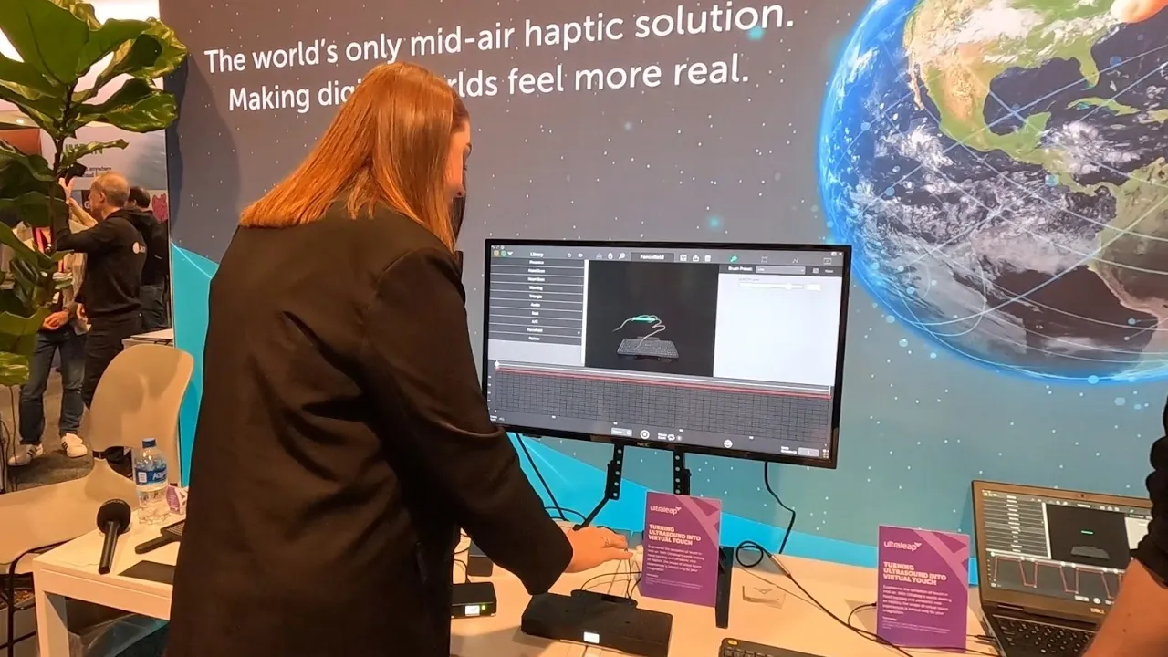
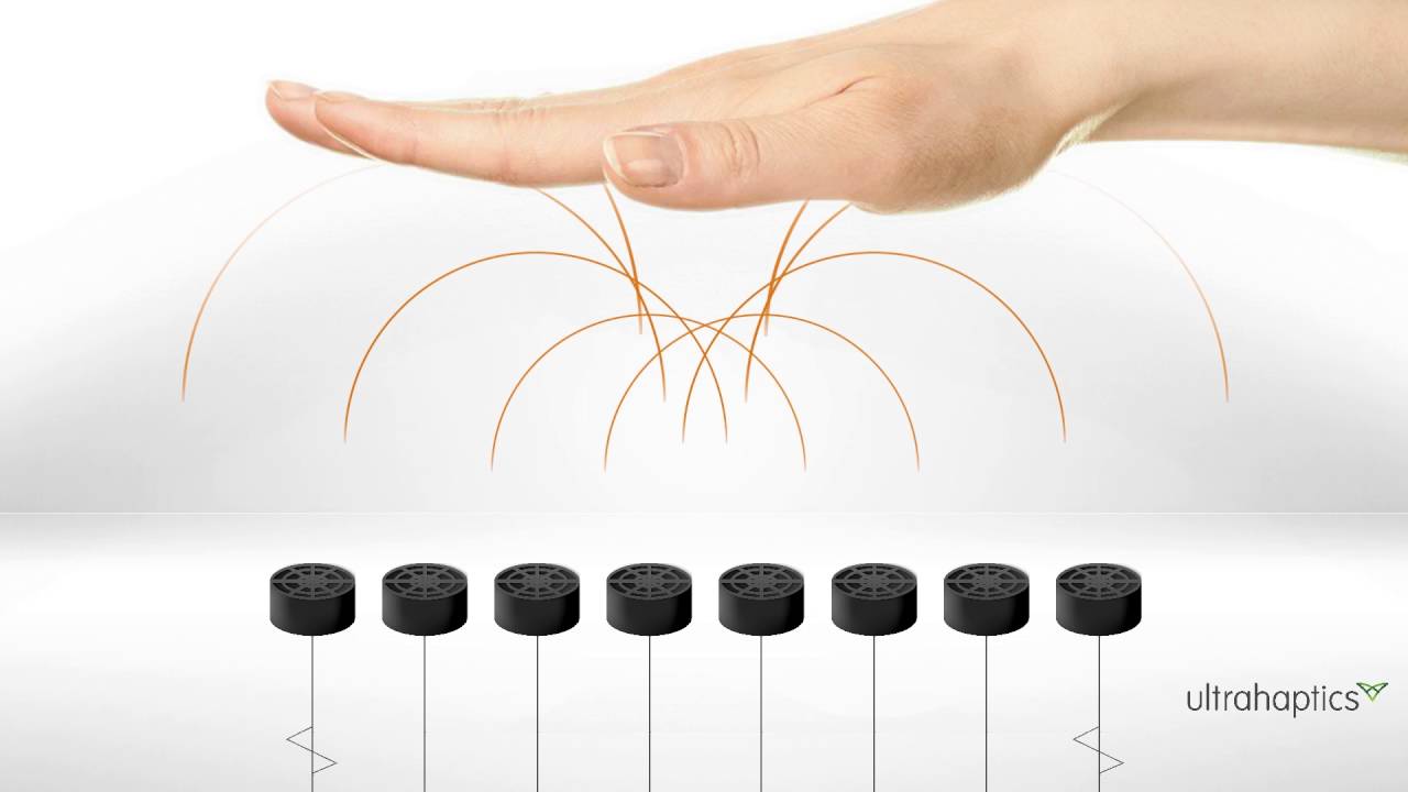
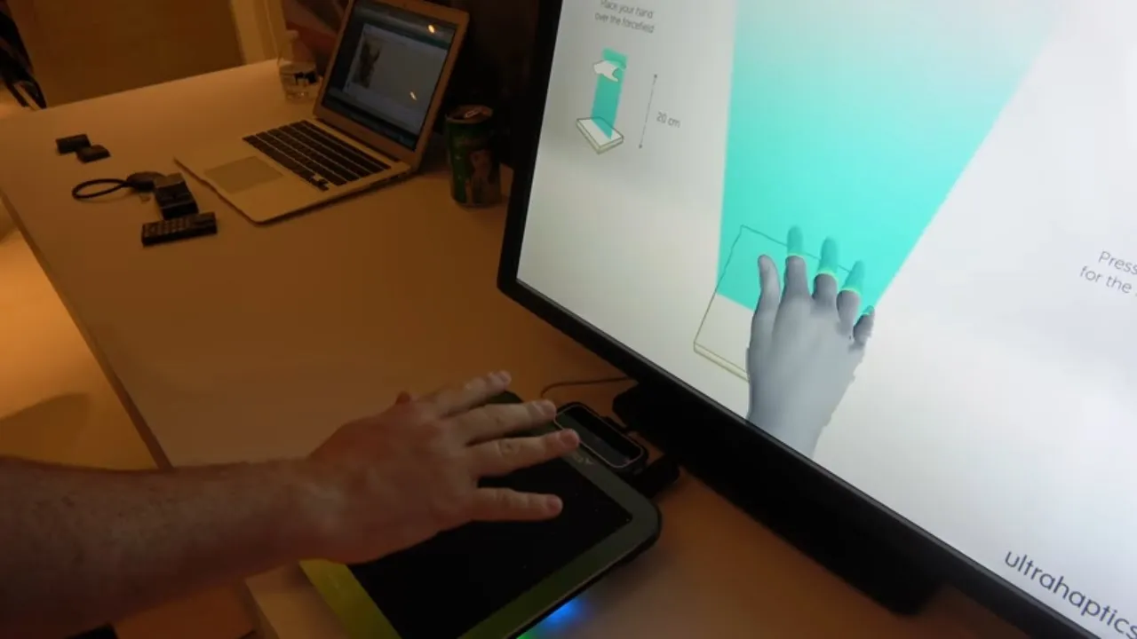
Investigating mid-air haptic feedback systems that use the same ultrasonic phased arrays to project tactile sensations.
Studying closed-loop feedback systems using high-speed cameras to dynamically stabilize and correct particle drift from air currents.
Comparing acoustic trapping with optical trapping (optical tweezers) and their respective scaling limitations in biomedical engineering.
1.7M views79.8Klikes10:19Original Release: 2021-03-14
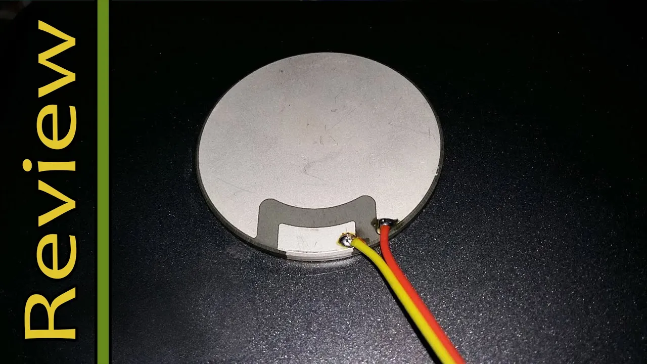
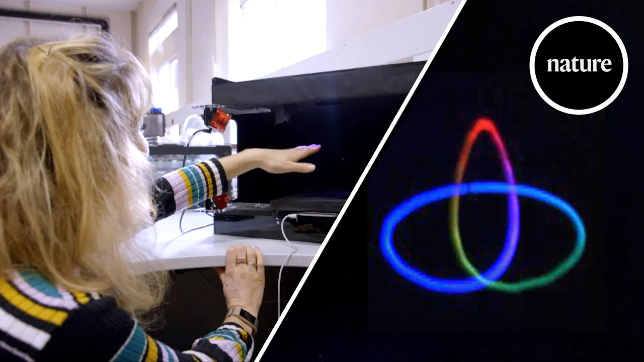
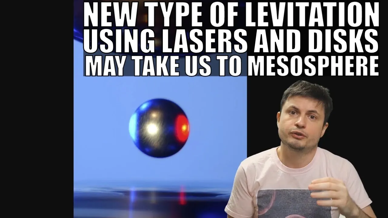
about five years ago I showed one of my kids a clip by physics girl of an ultrasonic levitator he immediately wanted to build one so we bought the kit and we spent most of an afternoon soldering it together he was pretty proud of himself and he decided to make a science fair project on sound I highly recommend you watch the physics girl clip as she gives a great explanation of how it works but essentially there are two opposing sets of ultrasonic transducer emitting waves of 40 kilohertz ultrasound 180 degrees out of phase with each other that creates standing waves of low and high pressure where a light object can hang out the bowl shapes that the transducers sit in helps Focus the sound fast forward about four years and I ran across an interesting paper in the journal Nature of a group at the University of Sussex who took this concept further way further essentially they use the phased array of ultrasonic transducers to move a Styrofoam ball through the air so quickly they were able to draw floating images in midair of course I had to build one the first step to building this was to figure out how it worked the paper was a great help here each transducer needed to be fed at 40 kilohertz waveform but with a phase relative to the other transducers calculated to ensure that the high pressure areas converged at a specific point in 3D space moreover the signals from the downward firing transducers had to be 180 degrees out of phase with the ones firing upwards the function here takes the focus Point as an argument and for each transducer calculates the distance from the focus point to the transducer multiplies that by the so-called wave number that converts a distance into a phase and that limits the resulting phase to plus and minus 2 pi once I had a rough handle on the physics I built the simulation of the system see if it was even possible to do what I wanted here I'm showing how the resulting waveforms interact with each other for one to ten pairs of transducers the focus point is in the middle of the volume you can see how the waves reinforce each other as more transducers are added in the final design I chose to use 100 transducers for each of the top and bottom arrays the simulator calculates the phases for each of the transducers and then determines the pressure wave magnitude for every voxel in the 3D Volume each boxel in this case is one millimeter cubed and this total simulation volume is 100 by 100 by 145 millimeters the simulator uses Cuda and opengl to dramatically speed up the calculations this animation is showing a particle The White Square moving along the pre-programmed path simulation looked about right to me it showed all the standing waves as expected and it showed that it was possible to calculate the phases of the transducers to focus the sound and that it was possible to move the focus point with that validation I decided to build this thing the design consists of two identical boards each with 100 transducers each board also has a controller and memory and something to calculate and generate the phase signals for each transducer a Raspberry Pi is used to control the two boards transducers I Source are 10 millimeters in diameter and rated to 40 volts to drive each transducer I used a mosfet driver configured as a full H bridge to essentially double the power the university group had used figuring I'd be able to move the bead that much faster which actually turned out not to be the case to generate the transducer signals I decided to use an fpga this was partly because I needed a lot of i o pins more than 100 on each board and also because I wanted to be able to calculate and change the individual signal phases at a rate of 40 kilohertz something that seemed to be a stretch to do on a micro I'd hope to find an fpga in a tqfp package with enough I O and gates to be able to run all 100 transducers on each board but such a thing didn't exist it was simpler just to stick two fpgas on each board and have them each run 50 transducers I also added double ee prompts for each fpga to store images on one of the boards I put a Raspberry Pi W as the main controller the pi sends SPI commands to all fpgas simultaneously to keep the fpga synchronized one of the fpgas generates a 40 kilohertz synchronization's pulse that all the other fpgas listen to because I was a little paranoid about all the Emi I might be generating I decided to use rs-485 differential signaling to send the spy and sync signals from one board to the other to illuminate the foam ball I use four 3 watt RGB LEDs at Each corner of the ultrasonic array each color is driven by dedicated LED drivers the drivers can be pwm to change the relative brightness of each color lastly there are four DC to DC converters one to step to 24 volt input voltage down to drive the transducers to separate 3 volt and 1.2 volt converters to drive the fpga and Associated logic and one 5 volt converter to power the pi layout was done on a four layer board a simple python script positioned all the transducers drivers and Associated decoupling caps other than that there's not much special about this layout this is the fully populated PCB I did make a couple small mistakes on layout but overall the boards turned out well one small trick I learned with that early ultrasonic levitator the transducers have a polarity to them while there is a little plus sign on the underside of each transducer it turns out to have no bearing on reality you essentially have to test each transducer to determine which pin is positive testing is pretty simple with an oscilloscope just hook up the transducer to the scope poke the transducer cone with a little piece of plastic and mark the pin that gets you a positive going Spike like the image on the left the fpga code is not super complicated an SPI interface allows the pi to send commands to the fpga one of those commands loads point in color data into a fifo a controller then coordinates the processing of each point into phases that are then used to drive the transducers there's also a separate module to drive the LEDs through the initial test of the system I use my simulation code to figure out the phase for each of the transducers this phase data was then sent to the Raspberry Pi that then sent SPI commands to the fpgas the fpgas then output phase signals to the transducers this simple approach allowed me to easily fine tune the algorithm for determining the transducer phases I just had to change some PC code it was also possible to determine if the ball could actually be moved it was a relief to see that it could at the moment the Precision of the system is 0.1 millimeters The Next Step was to have the fpgas actually do the math to determine the phase for each transducer based on a desired position command most of the code to do this is integer math but there are a few floating Point operations in there as well this simulator helped a lot to debug this portion of the code especially the timing what I ended up with was a pipeline that took in the desired ball position and then calculated the transducer phases for all 50 transducers connected to the fpga this took 94 clock Cycles at 20 megahertz note that these calculations are done 40 000 times a second now that the fpga was doing the math I was able to test how fast I could move the ball this video is showing the ball taking 60 milliseconds to move 60 millimeters in one direction or about 1 meter per second when conditions are right I've been able to double that speed but I can't do it reliably and I don't have the patience to further tune the system here I'm drawing a line by moving the particle back and forth quickly circles are rather easier to draw as you never have to slow down and stop I wanted to replicate the butterfly animation the original researchers had made so I created a simple scripting structure that allowed me to show a particular set of points for a specified number of times and then jump to the location in memory that contain the next animation frame this butterfly animation fits in 8 000 words of memory about the max I could put in the fpga I've not gone around yet to using the external double e problem to store data in this clip the butterfly is moving and rotating while animating I added a simple preprocessor to the points read from Ram in the fpga to multiply the 3D points by a rotation and translation Matrix this was all done with integer math the pi can then send commands in real time to the fpga supplying the coefficients to this rotation and translation Matrix you can also scale the object down in size for this clip the Raspberry Pi is sending these coefficients every 100 milliseconds to the fpga causing the butterfly to move and rotate one last thing if you recall there are some RGB LEDs on the board this allows me to turn on different colors of LEDs at different times in an animation frame to essentially color the Styrofoam ball with light each point has seven bits of color information associated with it which was all I could fit in the fpga's internal Ram and here you're seeing each butterfly wing with a different color so that's pretty much it you can see there's some Distortion in the shapes I think I've ruled out any error in the firmware and I'm attributing these distortions to the cheap transducers having trouble adjusting phases so quickly but it could be something totally different as to next steps there are a few things I'd like to do I like to try moving multiple balls at the same time it should be possible also the original researchers were able to turn this into a haptic device if I modulate the amplitude of the focus point at about 250 Hertz that should stimulate the nerve endings in my finger allowing me to feel the 3D points that's definitely pretty cool and lastly I should be able to create a very directional audio speaker using these phased arrays of transducers I'm not sure I'll ever try that but it sounds interesting anyways let me know what you think happy to answer any questions
Up Next

86:56
Interfacial Rheology Explained: Theory, Measurements, and Applications
@TAInstruments
12.4K views•2013-07-10

12:53
21cm Hyperfine Transition in Neutral Hydrogen: Radio Astronomy Basics
@AaronRobertParsons
12.4K views•2011-10-13

32:32
NMR Spin Physics I: Zeeman Effect, Resonance Condition & Larmor Frequency
@nptel-indianinstituteofsci8064
2.3K views•2024-01-17

27:14
Entropy and the Second Law of Thermodynamics Explained
@veritasium
27.5M views•2023-07-01
Related Study Plans & Knowledge Roadmaps
Structured learning paths in Physics
physics
Nuclear Physics (Decay, Fission & Reactors)
01Atomic Structure and the Binding Force
02Radioactive Decay and Half-Life
03Nuclear Fission Mechanics and Chain Reactions
+ 2 more learning modules
12h5 modules
Explore Roadmap
physics
Soft Matter (Polymers, Colloids & Rheology)
01Foundations of Soft Matter & Thermal Forces
02Polymer Physics and Macromolecules
03Colloids, Surfactants, and Self-Assembly
+ 2 more learning modules
38h5 modules
Explore Roadmap
physics
Analytical Mechanics: Lagrangian & Hamiltonian
01Mathematical Foundations: Calculus of Variations
02From Newtonian Mechanics to Constraint Dynamics
03The Principle of Least Action & Lagrangian Mechanics
+ 3 more learning modules
28h6 modules
Explore Roadmap
physics
General Relativity (Spacetime & Cosmology)
01Foundations of Relativity: Special Relativity
02The Geometry of Spacetime: Equivalence Principle & Curvature
03Einstein's Field Equations: The Mathematics of Gravity
+ 2 more learning modules
55h5 modules
Explore Roadmap