










![12(a). Fundamentals of Sinusoids | CSE250 Fall'24 - [PDS]](https://i.ytimg.com/vi/XCmIw9erWh8/sddefault.jpg?sqp=-oaymwEmCIAFEOAD8quKqQMa8AEB-AH-CYACzgWKAgwIABABGH8gFygZMA8=&rs=AOn4CLBO7V-dsKkNa5su5oJWCiOlsnZ8sw)


![オシロスコープ初心者必見!プロが教える電子機器開発必携ツールオシロスコープを、BARAと一緒に入門しよう! [IBUKA LAB 034]](https://i.ytimg.com/vi_webp/nTZxLbOmXLk/maxresdefault.webp)







![[Szambo technologiczne] Tanie ładowarki USB](https://i.ytimg.com/vi/eZt9tHopefs/maxresdefault.jpg)
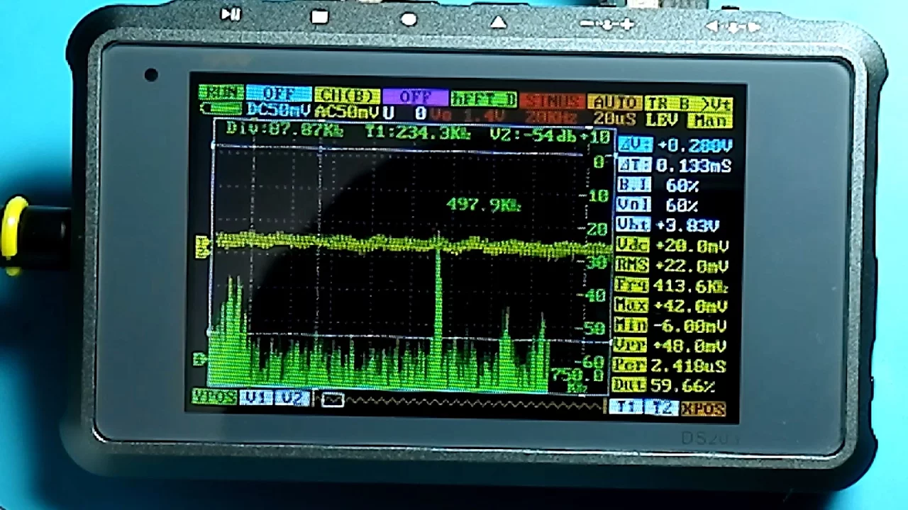


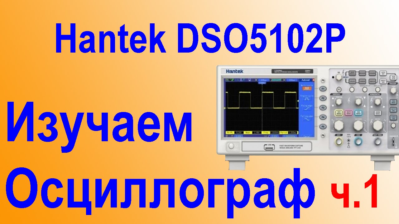
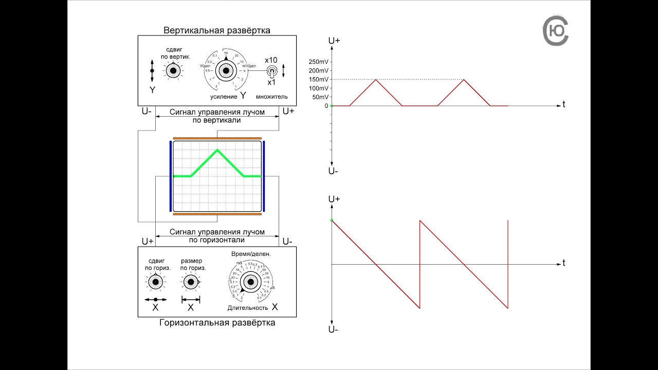
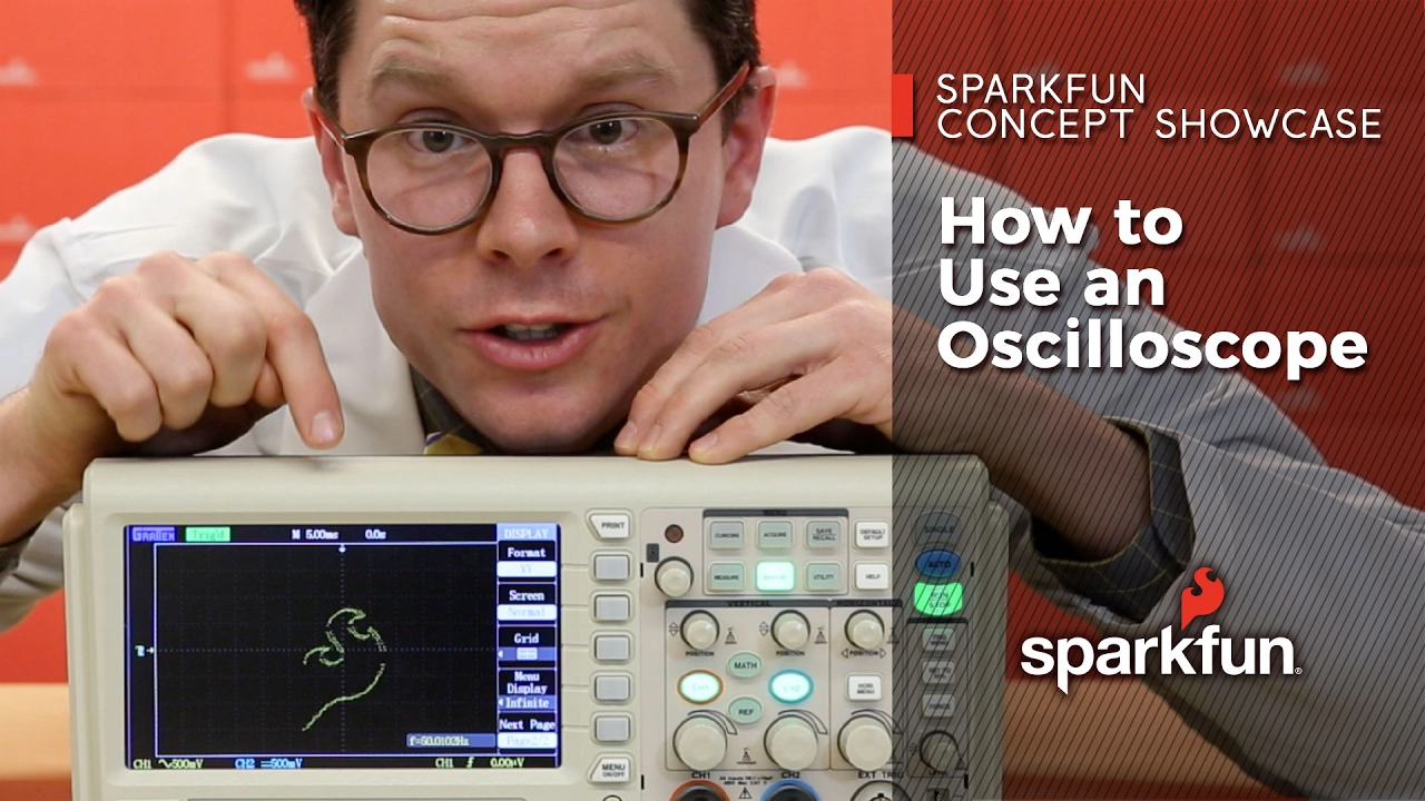
This video teaches beginners how to operate an analog oscilloscope's Y-axis (vertical) controls for voltage measurement, including probe calibration using the onboard square-wave generator. Key concepts include: (1) The oscilloscope probe has an x1/x10 switch that attenuates the signal by 10x, requiring corresponding adjustment of the vertical deflection knob to maintain proper waveform height; (2) Calibration involves connecting the probe to the probe adjust output (which provides a known 0.5V peak-to-peak square wave), setting the vertical deflection knob so the square wave occupies exactly one vertical square on the screen, establishing that each vertical division equals 0.5V; (3) Probe compensation (the tiny screw on the probe) must be adjusted if the square wave appears distorted, ensuring linear response between x1 and x10 settings; (4) The vertical deflection knob controls how much voltage causes the beam to move vertically, enabling voltage measurements by counting how many squares the waveform spans.
Analog Oscilloscope Basics: Voltage Controls & Probe Calibration
Added:well greetings out there in YouTube land and welcome to the beginning of a new video series it's going to be on a topic that I have probably had more viewer requests for than any other topic I can recall I'm going to try to cover the basics of oscilloscope usage and how you can use the oscilloscope to diagnose problems in tube amplifier circuits now this is a massive topic it would take many videos to cover all of the applications of this device but I don't really think you need all that what I'm going to cover is my own basic knowledge of the instrument and you can carry it further if you wish but I think when we get through you're gonna have a pretty good understanding of how the oscilloscope works and how you can use it in a constructive manner to diagnose problems with your tube amp circuits in preparing for this video I watched a bunch of other videos on YouTube that were dedicated to the basics of oscilloscope usage and I'm going to tell you in most cases I got confused watching them they talked way too fast and they covered way too much information they jumped around and the one thing that really bugged me is they would just start flipping switches and to get the desired image on the screen without really explaining to you what they were doing so I'm gonna try to avoid those pitfalls I'm gonna go very slowly and methodically through this and try to explain everything to you and we're gonna try to move in an incremental pattern where we start with the utter basics and build on that so if that sounds like something that will work for you then please stay tuned and let's get started now hopefully you all watched the preceding video in which I discussed isolation transformers and they're used with oscilloscopes I have not yet received the parts that I've ordered to build my own isolation transformer they should be here this week and I will prepare a video of the process by which I build this isolation transformer and then once I have mine and hopefully you have yours we'll be able to proceed on using our oscilloscope to do some troubleshooting and signal checking in amplifier circuits until then until we have our isolation transformer I'm just gonna stick with the oscilloscope and the signal generator and we'll see if we can't learn how to operate the controls so that we'll be ready to do some troubleshooting on an actual amp circuit also in the isolation transformer video I discussed the probes that we'll be using with our oscilloscope we have the little hook to hook onto wires in the chassis under study we have the possibly hazardous ground connection that we know that we need an isolation transformer for the device that we're testing so that the hazard is removed from this and also we have the mysterious x 1 and x 10 switch that was discussed in that video with the x 1 position of the switch we have a 1 mega ohm resistor in series with the signal that's going to be coming in from our electronic device that we're evaluating before it can go into the innards of the oscilloscope now one mega ohm is going to give you quite a bit of protection against a sudden onrush of current or extremely high voltage coming in here to damage your scope now the thing is with this it gives you greater flexibility because say I want to hook onto something that's 400 volts at x 1 then I would have to have a vertical axis here that could show 400 volts now I can click in values for each of these squares but I cannot click in enough value per square to show 400 volts on the screen therefore before I hook on to that I'm gonna switch this down two times ten to cut the 400 volts down to 40 volts which I then can see on the screen and will be a manageable deflection of the sine wave or whatever type of image that I have on my skull so this gives you great flexibility as far as the voltage readings that you connect to one thing you have to remember though is if you go to times 10 remember that the image on the screen is one-tenth as tall as it should be the times 1 you will get the valid height now the oscilloscope probes are connected to the input jack here with a BNC connector they're gonna push on and then this rotates to lock them in place the outer surface here the perimeter is going to be the shield and inside is the little hop pin that is going to bring the signal from our circuit under test into our oscilloscope to be manipulated by the electronics within now let's get to the mysterious screw that many of you have been wondering about this would be a good time for you to attach either one of your probes if you have a single channel oscilloscope or both of your probes if you have a two channel oscilloscope using the BNC connectors get them connected and put the little mysterious screw at the top of both of your probe connections without done let's push the on/off button and turn on the oscilloscope and let it start to warm up now that the scope is on and it's warmed up hopefully you're going to see a horizontal line across the screen if you don't see it don't worry where I'll show you how to find it okay on how to put it there now let's learn these four controls here one two three four as they will help us get this line where we want it and make it appropriate for our viewing number one let's go over here to the position control with arrows up and down just as it implies this will help us position that horizontal line I'm going to position it right on the dotted lines which represent the x-axis of my screen intensity is exactly what you're used to seeing you can make that line just as intense as you want I would back off and make it or I could see it clearly but nothing excessive let's drop down here to the focus knob and sure not just like it says it can be really a fuzzy line or it can be a super sharp clear line which is exactly what I want it to be now what if you don't see the line right now well let's say it's up at the top watch this I'm gonna push something called being fine isn't that what we're wanted what we're trying to do is find the darn being push it look at that it brings it down from up above it says hey I'm up here so then I know did I use my position control to bring it down now what if it was off the bottom of this go is the oscilloscope working now I'm not sure let's push being fine oh no I'm down here Here I am so we'll bring it up from the bottom okay so now we have changed the position of the beam we found it with beam find if it's not showing we have focused it into a sharp line and we have altered the intensity to where it's just fine for us to see but not excessive or damaging to the oscar's of this scope screen okay now what if no matter how much you try to focus you still got like three blurry lines or you've got something that's jumping all over the place and it won't hold still well I'm gonna direct your attention over here to the top right corner of at least of my scope to something called trigger now I will explain this in more detail later but for now try adjusting the trigger until that lines see I went too far I'm gonna adjust it and watch when I get trigger set just right look at rock-solid straight line it's not jumping around if your line is jumping or it's three lines or four lines move the trigger knob for now without knowing exactly what you're doing just move it until the line settles down one other possibility if you can't see the line even now you might look over here at the trigger section and move the slide switch that says mode just move it over to TVLine you'll have no idea why or what this is actually doing but if you move over to TVLine your line may magically appear on the scope now it's time to start using our probes and we're gonna start off with the probe you notice that as the red line there and the red line there I want the probe for channel 1 okay and what I'm gonna do is come over here and if you'll look you should have a little kind of a little stud that comes out the front of the amp and it'll say probe adjust now set your slide switch 2 times 1 and hook the little hook at the end of your probe to that probe adjust that is protruding from the front it may be a loop or like a horseshoe in my case it's a like a little nail head hook your probe onto it and if you have another connection for ground I have it here but it requires a jack to slide in so what I'm going to do with my ground is if you've got a little ground loop hook your ground alligator clip onto it if you don't just hook it on to the exposed piece here of this BNC connector now we have made a closed circuit with our oscilloscope okay we have the probe for channel one connected right down here to the probe adjust stud and it is receiving from a circuit within the oscilloscope a square wave which we're going to use to calibrate our probes that signal is coming down here and is coming in right here into the oscilloscope now to get the image properly on the screen we're gonna have to make some adjustments okay right here where it says AC ground or DC go to AC because square waves are alternating current we're gonna tell the oscilloscope it's gonna see a form of AC over here it says mode now mode is one of those terms it can be a little confusing but it really doesn't matter when you think about that what each of these switches says this one says do you want to see channel one on the screen do you want to see both of them at one time or do you want to see channel two well since I only have the probe connected here in channel one let's set this over to channel one that's what I want to see over here do you want to see channel two upside down or right side up well I don't really care because I'm not looking at channel two yet but when I do it may be important but for now I'm just gonna leave it in the normal position and then over here we've got a dalton chop now god only knows what those mean you know so for now let's just leave it in the alt because ition and we'll discuss this at a later time so a real quick review we've got our probe down here at our probe adjust stud we've got the AC setting here we've got channel one norm and alt now you look at the scope and I've got this you don't tell him what you've got on your scope but let's set an adjustment to where we all have exactly the same thing on our scope okay I came over here and I removed my probe from the probe adjust to look at what the heck this is putting out and it says 500 millivolts okay peak to peak well 500 millivolts is a fancy way of saying 1 a half a volt okay so that's what is being put out from my probe adjust let me put my probe back on that log and look over here how can i reconcile that half of all with what I see here well that's where this knob which is probably one of the two or three most important controls on the whole oscilloscope comes into play remember our little probe was at 1x let's try putting 0.5 remember it's 500 millivolts is going out from our probe into the scope of thanks to our little that little stud down there that I'm connected to let's put point 5 volts over here where the 1x probe setting is and lo and behold how tall what is the amplitude of our square wave now notice this is a square wave okay that's a whole lot easier to work with because it's flat on the top and flat on the bottom so we're going to use it for this purpose okay the output from our probe adjust is a square wave so we're looking at it here and how many squares tall is our waveform if you say exactly one square you win the prize the reason it's one square high is no coincidence we just adjusted this knob so that each vertical square has a voltage value of 0.5 volts so we have an output signal of exactly 0.5 volts we set the scope to give us 1 square deflection on the screen 1 square for every point 5 volts and that's why our waveform is exactly 1 square tall looking at that then looking over at the knob setting you would instantly know that yes I have a square wave coming in here I don't know the frequency yet but that's gonna be something we're gonna learn also I don't know the frequency but I know the amplitude and I know that it is exactly 1/2 volt from here to here now if it made sense to you that setting the channel 1 deflection to 0.5 volts per square with this knob and then in putting into our oscilloscope 0.5 volt square wave and we see this on the screen and sure enough one square of deflection vertically is exactly point 5 volts just as I said it now if that makes sense to you that's it okay all the rest of this is just going to be cake I guess because that's the way oscilloscopes work what we have mastered then is the vertical deflection that is set by this knob we know that it relates to the voltage that's contained within the waveform so now we know about our y-axis deflection controlled by this knob let's go over to the second channel and see what we have by now I hope you're thinking well let's see this button right here our said channel 1 or channel 2 so I'm going to flip over to channel 2 and notice that channel 2 has its own position knob so I'm gonna run that down now I don't see a square wave okay I see a very very intense line but I don't see really a square wave can anybody tell me why I don't see a square wave over here in this channel for those of you said well because I'm only putting my signal into channel 1 this is my channel 2 probe I'm gonna have to hook it up you're right let's do it now I'm gonna take my yellow yellow test probe and hook it up down there to the probe adjust log to receive a point 5 volt square wave okay I'm all hooked up this doesn't look like the other one did so what do you think do you think maybe it has something to do with this knob setting here which on my scope right now is it like 20 to 50 something I mean that doesn't it was supposed to be point 5 let's click this around to where point 5 shows up just like it did here and look what we have isn't that mysterious we have exactly the same square wave with exactly the same 1 square vertical deflection that I set with my channel 2 voltage knob okay isn't that's it that's kind of nice isn't it and we can move it up and down we can move it all over the place it has it's very own position setting okay so I'm gonna set it right there where the base is on the x-axis okay and it's still exactly 1 square of deflection because I told it to deflect one square when you see 0.5 volts and then I fit in point 5 volts down here and it did exactly what I asked it to now the last knob that we're going to master in this video is going to be the little scrawny knob that's in the middle of both of these knobs and it says Cal and it has an arrow now I'm wondering what that's all about okay so I think since the number 2 channel and probe are the only ones that are receiving a signal and they're the ones I'm watching on the scope according to this slide switch that says you're just watching channel 2 let's turn it and see what happens well look at that you see the deflection change what this is is a way to calibrate this screen responds to the knob setting if it isn't exactly perfect this is like a fine tune okay and I don't really think we're gonna need it but I just wanted you wanted you to know what the meaning was at that little knob okay and to be honest with you I never mess with it okay now for the icing on the cake let's try to figure out what that little screw does okay so there's going to be several steps that we have to go through before we can figure that out number one reach down on your probe the yellow one in my case and switch it to times 10 okay now look what happened to my square wave it collapsed it's there it's just flat because now it's one-tenth as tall as it should be so let's crack in a little bit lower voltage for it I'm going to crank my channel to volt knob from 0.5 where I had it all the way over to about 20 millivolts and look what I have a really nice looking square wave so as you can see when the minute I clicked in The Times 10 on the probe I had to compensate by changing the voltage deflection by putting in times 10 my score would wave collapsed and then I had to give it a more and more sensitive deflection value to get it back up to this height okay so you see the interaction and why you have to be careful with your slide switch settings on these probes right now it's at times 10 okay this is what I have now you may not have this you may have something that looks like this like the Raggedy a square wave anybody ever saw well if that's what you have put a tiny little screwdriver down in and crank that tiny screw and calibrate your probe so that it has linear response for x 1 and x 10 that means you'll get the same waveform if it's at x 10 as you did at x 1 now grant it at x 10 it'll be shorter because it's 1/10 that's tall but it will be the same shape well it was so much fun let's try it with the red probe from channel 1 I hooked my red probe up over here to the little point 5 volt square wave output and I've hooked my ground lead right here to the BNC shield and I don't see anything here does anybody have any ideas oh wait a minute how about this remember if you want to see channel 1 on the screen you go to show at channel 1 okay now that looks a little intense to me so I'm going to back off the intensity and once again it maybe it's collapsed let's crack channel 1 over here oh look what we're seeing and when I get to 20 millivolts look what I have looks very similar to what the channel 2 Pro produced isn't it but what if your square wave looked like that well as I recall from channel 2 I turn this little screw here until that top is flat and it's just as square as Abe Lincoln's hat ok so now I have calibrated this probe so that the response then is linear between X 1 and X 10 both of my probes are now calibrated well now as a school teacher kids used to love it when I'd give them extra credit questions so I'm going to give you one now and see if you can figure it out I've got the scope set up here and the way that we're used to seeing it we're on channel 1 we have 0.5 volts it per one square deflection which means that if the amplitude of the wave Rises 1 square then that is an equivalent to 0.5 volts which you know is 500 millivolts however when I shift at times 10 my scope image becomes 1/10 is high now it is if I home in here actually two separate lines one tenth as high as they were when I was at X 1 so here is your question what can I set this knob to where the square wave at X 10 will look exactly like the square wave at X 1 I mean the same height everything the same think about it where can I set this to make that happen if you wish why don't you stop the video so you can have a little time to think about it okay here we go now there's several ways to approach this problem if the output of the square wave generator is 0.5 volts and that output is diminished to one-tenth by switching the probe from X 1 to X 10 then the modified output is going to be 0.05 vaults this is the same as 50 thousandths of a volt one thousandth of a volt we know as a millivolt so this is the same as 50 millivolts this conversion is necessary because it's the way the oscilloscope is calibrated well let's see if it works point-to-point 1.05 there it is exactly the same square wave so by altering this setting to 1/10 we now exactly match a voltage output that was diminished to 1/10 so 1/10 the voltage once out the setting you get exactly the same screen plot now I'm not sure if some of you noticed but there is a shortcut instead of calculating 1/10 of the original 0.5 volts we can simply use this indicator over here when we shift it to a 10x probe to get the voltage per vertical square deflection value okay so you can divide by 10 and use this as your indicator or not do any division and simply use the 10x probe indicator to dial in your point 5 volt value if you got it right then congratulations you're well on your way to the scope Hall of Fame ok that's about it then for this session I think it best that we break it up a little bit so that you can thoroughly digest the information that's been presented I want to take a few seconds here to thank some viewers for some very generous gift first will be from Jim I got this set of ten a dial plates which will really spruce up my homemade amps and second Randy for sending me such an incredible gift that it's going to be the subject of its own video series in the near future I also want to thank all of those viewers who are made patreon pledges and PayPal contributions it's your generosity that keeps this channel on the air and free of advertising should any one else out there in the audience want to join in and help I've included links in the video description thank you okay I think that's about it for this part 1 video I'm hoping you're really anxious for part two to keep on learning what I recommend to you for homework is that you go in here and mess up the knobs the ones that we've learned about ok go ahead and change them all around so that everything's screwed up on the scope then come back and systematically locate where is my scan bring it to the center get it focused get it the proper intensity set your different voltage deflections for it you can use this as your signal generator right here for now until you get your own in part two we'll probably start using the signal generator and you guys that don't have them or going to be it at a loss because we're going to go into sine waves and we're going to be able to generate all sorts of different waveforms to study but if this part made sense to you the y-axis of voltage deflection set by these two knobs in our two channels then the rest of it I don't think is going to be challenging ok so practice study try to get where you're good at it it's like playing tennis and I'll see you again in part two here's that little track team roadster idling I guess he's warming it off before he hits the road nice great sound [Music] I just couldn't resist spending a little more time with his 409 edge and any final look at this craftsmanship and attention to detail it's about ten times harder than it looks really something okay that five-window coupe with the bar on is getting ready to leave I thought you're not gonna check out this end of this day a lot of territory sauce in the car how about this for a nice whole 55 Chevy two-door post look at them straight as an arrow with I'm not a fan under skirts but some people love them there they are [Music] [Music] overall a nice presentable car there goes the 32 roadster I asked the guy in the little Model T truck he said he was built in Canada and it does have a Pinto 4-cylinder which is about all the engine you could fit under that tiny hood he just got it
Up Next
Cryptocurrency Signatures: Hash-Based to Elliptic Curve Systems
@mitocw
40.5K views•2019-07-12

Triumph of Orthodoxy Icon: Byzantine Art & History Explained
@BenCallan
2.1K views•2024-08-06

FastAPI vs Flask vs Django: Choosing the Right Python Web Framework
@TechWithTim
302.5K views•2024-05-26

Game of Thrones Opening Credits: A Cinematic Analysis
@gameofthrones
46.3M views•2011-04-18
Related Study Plans & Knowledge Roadmaps
Structured learning paths in General & Interdisciplinary Studies