








![#2 Instrucciones Básica [ pinMode, digitalWrite, delay ] - Curso Arduino 💻](https://i.ytimg.com/vi/dwet3or5rmQ/maxresdefault.jpg)



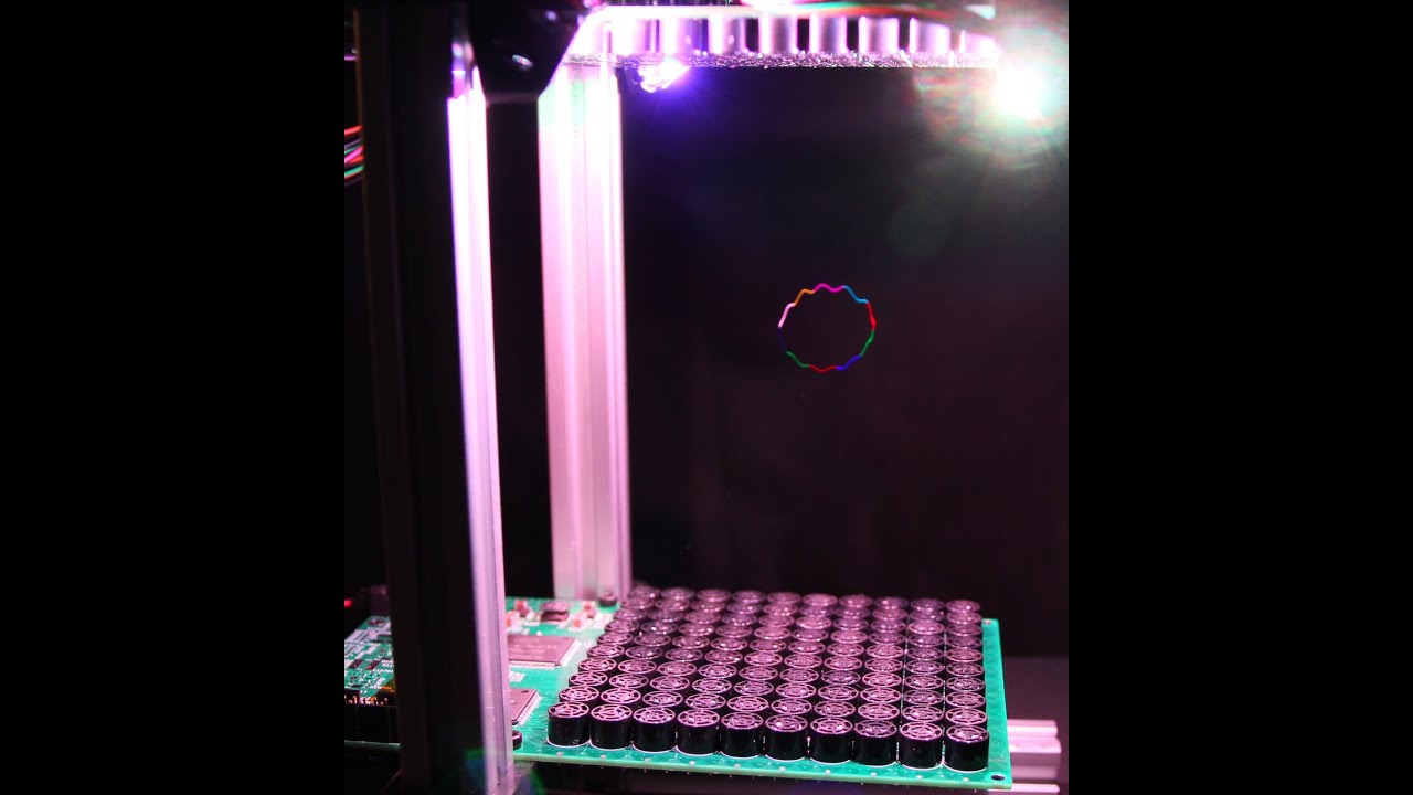
![Three-Dimensional Mid-Air Acoustic Manipulation [Acoustic Levitation] (2014-)](https://i.ytimg.com/vi/odJxJRAxdFU/maxresdefault.jpg)




![Bart Rimez et la microfluidique: des recherches appliquées [L'Objet de la Recherche #11]](https://i.ytimg.com/vi_webp/YTRyHVouBwA/maxresdefault.webp)






Ultrasonic levitation works by creating standing waves from two opposing ultrasonic transmitters operating at their resonant frequency; these standing waves form pressure nodes where lightweight objects become trapped and levitate midair, with the distance between nodes being half the wavelength of the sound wave.
Build an Ultrasonic Levitator: A Step-by-Step Physics & Electronics Guide
Added:Basic wave mechanics, specifically the principles of wave interference, frequency, wavelength, and the formation of standing waves.
Fundamental DC circuit theory, including Ohm's law, voltage, current, and how to read basic schematic diagrams.
Introductory microcontroller programming, specifically familiarity with the Arduino IDE, writing basic sketches, and utilizing GPIO pins.
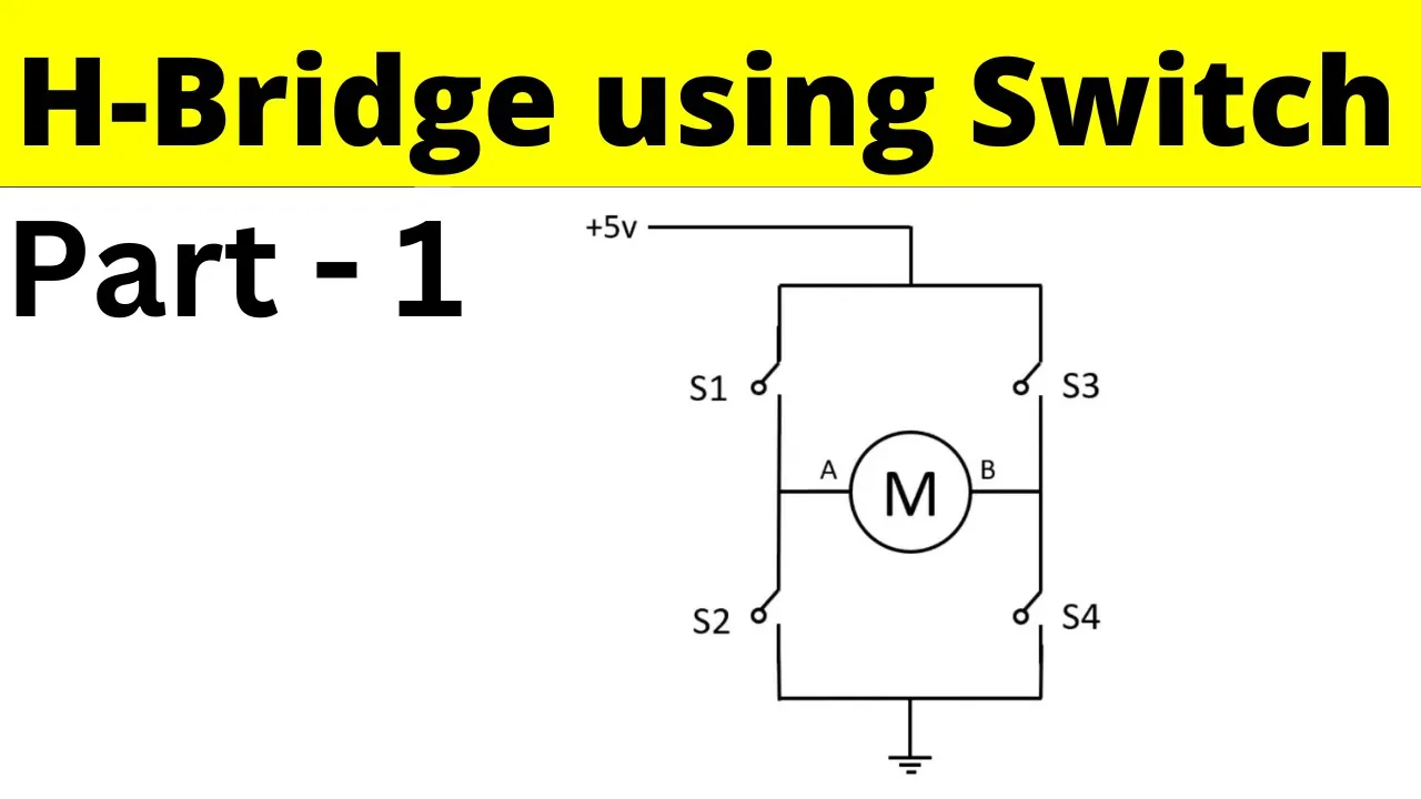
The operational concept of a semiconductor switch and how an H-bridge circuit is used to control polarity and power delivery.
Acoustic phased arrays and phase-shifting algorithms to dynamically move and manipulate levitated objects in three-dimensional space.
Advanced acoustic physics, specifically calculating acoustic radiation pressure and understanding the Gor'kov potential field.
Real-world applications of containerless processing, such as contact-free chemistry, pharmaceutical crystallization, and microfluidic manipulation.
High-frequency circuit design, including impedance matching for ultrasonic transducers and designing custom driver PCBs.
15.4K views150likes32:35Original Release: 2025-07-31
This is an ultrasonic levitator.
Two transmitters facing each other send out waves of sound that humans can't hear. These opposing waves create a standing wave which has nodes of constant air pressure. Lightweight objects like these pieces of foam can get stuck in these nodes and levitate in midair.
In this video, we'll cover all of the physics and electronics you need to build your own.
Let's start by talking about the physics.
Sound waves are made by vibrating air particles that bump into each other.
These vibrations travel through the air as compressions where the particles are closer together and rarifactions where the particles are farther apart. Note that there's no net displacement for any individual particle. While they vibrate back and forth, overall the individual particles don't move from left to right.
Rather than drawing all of the individual air molecules, many times we represent a soundwave by a sine wave as pictured here. The y-axis of this graph represents air pressure, which is higher where the molecules are packed more closely together. A larger amplitude wave with a bigger y-axis value represents a larger change in pressure, which means a louder sound. We define the waves frequency or pitch as the number of wave crests that pass a point in 1 second. We measure frequency in a unit called hertz. Human hearing extends to a range of up to about 20,000 hertz or 20 kHz.
Ultrasonic sound is sound above that frequency that humans can't hear. Now something interesting happens when you aim two identical waves at each other.
that is sound waves with the same amplitude and frequency like the red and blue waves traveling in opposite directions here. The waves interfere with each other and their amplitudes add up represented by the black line. This is called a standing wave because it appears to just oscillate in place without traveling left or right. The standing wave has nodes represented by the red dots where the two opposing waves always cancel out resulting in zero amplitude. Now, here's what that looks like if we go back to representing the individual air particles. Note that this animation was created for a wind instrument, but the concept is the same for our ultrasonic levitator. The resulting standing wave has both pressure nodes where the air pressure is constant and displacement nodes where the air particles do not move. In our ultrasonic levitator, the floating particles get trapped in the pressure nodes. Circling back to our demonstration, we can now understand why the bits of foam seem to snap to certain locations, and I can't get them to hover right next to or touching each other.
They're getting stuck in the pressure nodes, and the distance between those nodes depends on the wavelength of the sound. In this case, that's about 8 mm, and the nodes are half a wavelength apart, or about 4 mm, which is about what we see here. Now that we've covered how it works, let's talk about how you can build one.
So, here's what I didn't show earlier in this video. All of this is being controlled by an Arduino. And if you've never used an Arduino before, don't worry. We have an excellent Arduino tutorial series on our YouTube channel, so you can go check that out. We recommend going through at least the first few tutorials before you dive into a more advanced project like this. You can also find a link in the description to the written instructions on our site, which have a complete materials list if you're not sure where to get all these parts. So, again, if you're ready to dive right in, keep watching. But if you've never used Arduino before, you need to buy the parts. Go check out those links in the description before you continue. Now, the heart of this project is these little ultrasonic transmitters, which you can think of kind of like a speaker that just generates noise that's in the ultrasonic range, so humans cannot hear it. And you have probably seen these in pairs, a transmitter and a receiver that can detect or measure ultrasonic sound if you've ever used an ultrasonic distance sensor with an Arduino project. So these work kind of like a bat doing echolocation. They send out a burst of sound and then measure how long it takes to reflect back to the sensors. So you can obtain the transmitters by desoldering them from one of these sensors, but these sensors have a bunch of other parts on them that would then go to waste. So, you can also just buy them separately in bulk or in pairs where they are usually marked with a T for transmitter and an R for receiver on the back if you don't want to have to salvage your ultrasonic sensors. And again, you can find the links to buy those on the written instructions on our site in the description.
Now, what we're using the Arduino for here is to generate a 40 kilohertz signal. We want to turn this transmitter on and off 40,000 times a second. And that is going to make a little plate inside it vibrate. And those vibrations will transfer to the air molecules and it will generate the ultrasonic sound.
But we can't hear that sound. So if you turn one of these things on, how do you know it's working? And I am going to demonstrate that here with a tool called an oscilloscope, which you might not have access to, but that's okay. I'm just using it for demonstration purposes in this video. An oscilloscope is a tool that will show us a graph of voltage on the screen. And I have the oscilloscope hooked up to one of the ultrasonic receivers. And you can see that if I hold this receiver far away from the transmitter, there's really nothing happening on my screen. There's no voltage. But as I move it closer to the transmitter and hold it in front of the transmitter, we start to see a sine wave appear on the screen. And the closer I get to the transmitter, the bigger or the higher the amplitude of that sine wave gets. And that makes sense if we think about how sound works. The sound is spreading out from a point. And just like how somebody who's farther away from you is going to sound quieter than someone who is talking right in your ear, this sound is going to get stronger as I get closer to the transmitter. So if you do have access to an oscilloscope, that is one way you can demonstrate that your transmitter is working even though you cannot hear the sound yourself.
Now, I should also mention that if you do have access to benchtop laboratory equipment like an oscilloscope, you may also have access to a function generator. And you can use that function generator to generate a 40 kohertz square wave or sine wave and then use that to drive your ultrasonic transmitter instead of using an Arduino.
However, function generators are usually more expensive, something you'd only find in say a university electronics lab and not something people usually have at home, whereas Arduinos are much cheaper and pretty widely accessible. So, in this project and in the rest of this video, I'm going to show you how to generate that drive signal to control the transmitter with an Arduino.
Before we do that, a few more quick notes about these transmitters. One is that some instruction I have found online say you need to check for the polarity that these have a positive pin and a negative pin. With the ones I purchased, I have not encountered that problem, which I can demonstrate here by just reversing the alligator clip connections to the pins. And then we see that I still get a signal on the receiver. So that did not stop it from working. I have also actually not found that much of a difference between the transmitters and the receivers. I'm actually going to hook what is labeled as a receiver up here and use it as a transmitter. So, I'm driving it with that 40 kHz square wave. And we see when I do that, I still get a signal on the other receiver. So, again, this might vary if you buy them from a different supplier than I did. You might need to check the polarity on yours and test to see which ones are transmitters and which ones are receivers because some are not labeled at all. We could go down a whole tangent about the physics of microphones and speakers and how they can sort of work in reverse. So a speaker can act as a microphone or a microphone can act as a speaker and vice versa, but not going to bother with that in this video. Point being, just go with how they're labeled to start. And you may need to test them if they're not labeled to figure out which one works best as a transmitter. You don't actually need the receivers for the build in the project. I was just using that as a demonstration here to show you the results on the oscilloscope.
Switching over to the computer for a minute to look at Arduino code that we could use to generate a 40 kilhertz signal. You'll see that we have a very simple program. And remember that if you are not familiar with Arduino programming at all, you should really go check out our intro tutorial series before you continue. We have a program that just declares a variable to tell the Arduino which pin we are going to use. And then we use the tone function to tell it to generate a 40,000 hertz or 40 kilhertz signal on that pin. However, there is a problem with trying this even though it looks super simple and easy that we will switch back over to the oscilloscope to demonstrate. So here I have the Arduino running the code you just saw and the ultrasonic transmitters aren't even connected. It's just hooked directly up to the oscilloscope to measure the output voltage on the pin where it should be generating a 40 kHz signal. So, we can see this nice clean square wave on the screen. That's the Arduino turning its pin on and off. But I'll see if you can see this if I zoom in a bit here. I have the oscilloscope set up to measure the frequency of that square wave and it's getting 41.67 or 41.58.
It's bouncing back and forth a little bit. KHz, so it's not getting exactly 40 kHz. And you might think, oh well, that's pretty close to 40 kHz, so that's probably fine. But it actually turns out that's a problem. And here's why. The ultrasonic transmitters are designed to be driven at their resonant frequency.
That means they generate the loudest ultrasonic sound when driven with a very specific frequency. As you can see from this graph where the xaxis is the actual drive frequency in kilohertz and the yaxis is the peakto peak voltage or amplitude of the signal measured on a receiver like I showed earlier in the video when it is held 1 in away from the transmitter. And you can see that that voltage is the highest meaning the signal it's receiving is the largest somewhere in between 40 and 41 kHz a little over halfway. So maybe in the 40,600 to 40,800 range. And with the Arduino, when we thought we were sending it a 40 kHz signal, we were actually getting about 41.67 kHz, which is all the way up here, well past the resonant frequencies. So getting much less power or sound output from the transmitter. And for our levitator to work, we really want to be driving the transmitter as close as possible to its resonant frequency. So, we're getting as much sound power or sound output out of it as we can. Now, the disclaimer here is that I collected this data myself using the transmitters I purchased. If you purchase different transmitters or salvage them from an ultrasonic distance sensor like we discussed earlier in the video, yours might have a different frequency response and you would need access to an oscilloscope to measure this yourself.
But the point for now is that we are not going to rely on the Arduino tone function to generate a roughly 40 kHz signal because it can result in something that is too far off.
Instead, we are going to generate our own output signal using the delay microsconds function. Now, if you've used Arduino before or if you've gone through our intro tutorials, you'll see that this code is nearly identical to what you would use to blink an LED on and off, say once a second. The difference is that here we are using delay microsconds. So, this delay is going to be much faster than the human eye can see.
Now you can do the math to calculate that to generate a 40 kHz signal you would need a period of 1 / 40,000 equals 25 micros. That means to generate a square wave you would need to turn the pin on wait half of the period or 12.5 micro turn the pin off then wait another half a period. However, the digital write command takes some time to run and slows your code down. This doesn't matter too much when you're just blinking an LED, but it does matter when you're trying to generate a really fast signal. So, I experimented and found out that if I lowered the delay time to 10 micro on an Arduino Uno R4, I got an actual output signal close to 40 kHz.
Switching back to the oscilloscope with our updated code, we see that I'm getting an actual output signal of 40.32 kHz. That's still a little below our true resonant peak of about 40.6 to 40.8. 8 kHz, but we're going to call that close enough and move forward with this code. Now, we're going to take a look at the hardware. First, let's see what happens if I just connect my two transmitters directly to the Arduino pin that's generating the signal. So, I'm going to take one jumper wire, go from my Arduino pin 3 to a row on my breadboard, and then take another jumper wire and go from the Arduino's ground pin to a row on my bedboard. I'm then going to connect alligator clips to jumper wires. Plug one into the same row as that ground jumper wire, one into the same row as the jumper wire for pin three, and then the other ends of the alligator clips are going to go to the two pins on my transmitter. I am then going to connect my second transmitter in parallel to the first one, meaning the jumper wires are going to go in the same rows. Ground jumper wire there and the other jumper wire here to the row with pin three.
I can test this by holding one of the transmitters over the other and then grabbing a small piece of packing foam with tweezers and trying to release it in between the transmitters to see if it will levitate. However, we can see that this doesn't really work. And this is because the Arduino pins are not really powerful enough to drive the transmitters directly and generate powerful enough sound to get the levitation effect. To do that, we need a more powerful power supply for the transmitters. And that is where an electronic part you may have seen earlier in the video called an Hbridgeidge comes in. Normally, this part is used to drive motors or something that takes more power than the Arduino pins can provide directly. What it allows you to do is interface those lower power Arduino pins with a part that requires a bigger power supply or more than the Arduino can deliver directly. So, as you can see, the wiring for this gets a little messy. We are going to switch over to the computer and a program called Tinkercad, so I can take you through wiring it step by step.
So, here I have an Arduino circuit set up in Tinkercad. This is a free online circuit simulator. There's a video about it in our intro tutorial series, so I'm not going to go over all the basics of how to use it here. I'm going to have the Arduino, the breadboard, and I'm going to go up here to the search bar and type L293D to bring out the Hbridge motor driver.
And I am going to rotate that 90° so the little notch and the dot are up at the top. And I am going to place it across the gap straddling the middle of the breadboard. So, you don't want to do it like this. And technically, you can put it upside down. That is fine. But then all of your connections are going to be reversed from mine. So if you want to fire follow how I am wiring it, I recommend doing like this. Doesn't really matter where you put it in the bread breadboard vertically as long as it is straddling the gap across the middle. Now there are a lot of connections to this thing, so bear with me. First, we are going to do the ground connections. And thankfully, Tinkercad labels the pins for you when you mouse over them. So you will see that this chip actually has four ground connections. That helps it dissipate more heat since motors and things that it tends to drive draw a lot of current which dissipates a lot of heat. So we are going to connect each one of those ground pins to a ground bus on the breadboard. That is the bus marked with a black line blue on some breadboards and a minus sign next to it. Note that the left and right orientation of your positive and negative buses may be switched depending on the bed breadboard you purchase. So don't go with absolute left and right here. Go with which whichever one is marked as minus on your breadboard. I'm going to do the same thing over here on the right. Going to go from the ground bus to those ground pins. And then I am also going to use a longer jumper wire. In the real world you'd be doing this with a jumper wire kit. Here I'm just clicking to add the wires in Tinkercad to connect the two ground buses to each other. And I'm going to connect one of those ground buses to my Arduino. So it is important that your entire circuit have a common ground when we get into higher voltage power supplies later. It is important not to shortcircuit the power supply voltage to the 5 volts from your Arduino. So we are going to keep our power buses separate for now. The L293D also has two power pins. One of them labeled power one here in the top right, that is your logic level voltage. So the control signal coming from your Arduino.
And the one down here in the bottom left labeled power two, that is the voltage that is actually going to power your motors or your speakers or whatever it is you're driving. And again, for now, we are going to keep those separate. So, I'm going to run this one to this power bus, and I'm going to run this one to this power bus. The one over here on the right, I am going to connect to my Arduino's 5 volts. But again, I am not going to connect the two power buses because later on in the video, I'm going to be adding higher voltages, and I don't want to short circuit that high voltage to the Arduino's 5 volts or that could damage your Arduino. Now that we have power and ground set up, we are going to wire the remaining pins on the left side of the Hbridgeidge, which are going to allow us to control our two ultrasonic transmitters. We aren't going to need to use the pins on the right side. They would allow us to control more transmitters if we needed them. Or if you're doing something like building a robot with multiple motors, you can use this chip to control more than one motor. But we're not going to need that here. So, first we are going to wire our enable pin, which is sort of like the master onoff switch. And while we could control that with an Arduino pin, we're just going to leave it on all the time.
So, we can just wire that directly to 5 Vs. Next, we are going to wire our first input that's going to control the transmitters. That is going to go to the Arduino pin that we are toggling on and off, which as you saw in our code earlier is pin three. So, I'm going to wire that to pin three. And then our other input, which is down here, I am just going to wire directly to ground.
So, that pin is always going to be off.
And we'll talk a little later in the video about a trick we can do with that pin to get more output out of the transmitters, but we're not going to worry about that for now. To represent our ultrasonic transmitters, we're going to add two PZO elements in Tinkercad.
This stands for PZO electric. It's the type of material that vibrates to produce sound when a voltage is applied to it. So, we're not going to worry too much about the physics of exactly how these work and that these are marked with polarity, a plus side and a minus sign in Tinkercad, even though we talked earlier about how I swapped those and mine still worked. Not going to worry about it too much. The point is we are going to wire the two pins of these PZO elements to the two output pins on the Hbridgeidge. So, I'm going to take one of my output pins, wire it to the positive side. I'm going to use a red wire for that. My other output pin, and this is where you have to start being careful because you wind up with wires crossing each other, and you don't want things to get too messy. So, that is one transmitter wired. And then I want to connect the second one in parallel or to the same rows on the breadboard that the first one is connected to. So, this one positive side is going to go there. I'm going to use a red wire to represent that. And negative wire is going to go here. And I'm going to use a black wire to represent that. So again, pause the video here if you need to or go to the written instructions linked in the description and you can get a screenshot of this video to take your sorry of this circuit diagram and take your time to build it one wire at a time. Make sure you keep things neat. If you're building this in the real world, use short wires so they don't cross each other all over the place and it's easy to debug. We try to avoid having wires crossing or blocking each other because then it's difficult to see where their connections are. Nine times out of 10 when someone emails us and said they followed the instructions and their project still doesn't work, when we look at their breadboard, there is a wiring error somewhere. So just one misplaced wire in one wrong row on the breadboard will prevent the entire thing from working.
So double check the wiring yourself.
Have somebody else look at it. Maybe they can spot a mistake that you couldn't get up and walk away for a while and come back and look at it again with a fresh set of eyes. There are a lot of connections here. 16 pins total on the Hbridgeidge. Again, we are not using all of them, but there's still a lot to connect and you need to make sure they are all right before you move forward. Now, we're going to switch back over to the camera because this is something I couldn't show as well in Tinkercad. Remember we talked about how the Hbridge is going to allow us to drive our transducers or transmitters with a higher voltage power supply, but we haven't connected that power supply yet. So here I have a 9V battery with a snap connector and a barrel plug on one end that's going to fit into the barrel jack on the Arduino. And that allows the Arduino to provide a higher voltage to the circuit. Now, the Arduino has something on board called a voltage regulator that converts this higher voltage power supply to 5 volts, which is still used by all of the Arduino's input output pins and the 5V pin. But on the Arduino here, we have a VIN pin, and that is going to provide the raw voltage from your power supply. So, what I can do is take a jumper wire, plug one end into the VIN pin and the other end into the power bus on the left side of the breadboard, which you remember from Tinkercad we had left unconnected before. I did not connect that over to the power bus on the right side, which is connected to my Arduino's 5 volts, because I don't want to short circuit those together. So, I'm going to take this jumper wire, plug it into the power bus on the left side, and then thanks to this little red jumper wire here, that is now powering my Hbridgeidge, which is going to power my transmitters with 9 volts instead of 5 volts.
So, if I adjust my camera angle so we can see this a little better, I can now test this and hold my transmitters above and below each other, grab a little piece of foam with the tweezers, and see if I can let it go in there and get it to levitate. And we see that with 9 volts, it doesn't work particularly well. I was able to get this to levitate a minute ago, of course, before I was filming. But I'm not getting it to work consistently with 9 volts. The 9V battery I'm using is a little old. So, I could try this with a fresh battery, but instead, I'm just going to go ahead and move up to a more powerful wall adapter power supply.
So, changing my camera angle again so we can see the circuit better. I'm going to unplug my 9volt battery and I have a 12v 3 amp wall adapter. So that can provide a lot more power and I'm going to plug that into the Arduino instead. Now you need to be careful here because the Arduino can only handle a certain voltage range on this barrel jack. So on the Arduino Uno R3, that's going to be up to 12 volts. On the Arduino Uno R4, it's up to 20 volt. So, if you want to power your transmitters with more than 20 volts, then you don't want to plug directly into the Arduino because you can damage the Arduino board. Instead, you can get one of these little adapters that has screw terminals that you can connect jumper wires to. And instead of plugging into the Arduino, you can still power your Arduino separately with the USB cable. And then you're going to plug your wall adapter into this adapter. and then plug both the power and ground connections from that adapter into the power and ground rails of your breadboard. Again, on the side that you had left open previously, not on the side that's connected to 5 volts from the Arduino. So, there is an option if you do get an even higher voltage power supply and you want to try driving the transmitters with a higher voltage. The other caveat there is that you need to check and see if you can find a data sheet for the maximum voltage your transmitters are rated for.
I actually could not find that information with these. So, I'm keeping it at 12 volts just to be safe for now because that got the demo working. Try higher voltages at your own risk. So, again, I'm going to plug that into the Arduino. My jumper wire is still in place. So, the Hbridgeidge is now being powered by 12 volts. Let's see if it works. So, here we go again. I have my Hbridge, which is now being powered by 12 volts. I have my transmitters. I'm going to hold one above the other and very lightly grab a little piece of foam with these tweezers and see if I can get it to hover. So, this can take some practice. If you grab the foam too hard, it will stick to the tweezers and not come off when you try to let it go in there. So, you want to grab it very gently and then sometimes you can actually drop it and as you move the transmitter up, it will sort of lift it up. And then you can try and grab additional pieces and see how many you can get stuck in there or how many nodes you can get going at once. As you saw in the beginning of the video, I got up to four. You can move this around to see how far away you can get them. Again, it can take some practice. You see there, I have two stuck together now.
And play with the acoustic levitation effect as you move this upper transmitter around. You can see what happens when you move it side to side.
or if you rotate it or move it up and down and see how long you can get things to levitate for or how far apart you can get your two transmitters and how many different nodes you can get something stuck in. You can also play with different sizes of these little foam bits. Try cutting them smaller or larger and see what works best. We have one more trick up our sleeves to get more output out of our transmitters. You may have noticed earlier that only one of the Hbridge inputs is connected to an Arduino pin and the other one is just grounded. Meaning this input is always going to be low or 0 volts. And we are never going to switch the polarity across our transmitters. So this pin alternates between high and low. So for example, there will be a positive 12 volts applied to the transmitter, but it never reverses. If for example I set this pin low to 0 volts and this pin high to 12 volts then there would be 12 volts applied in the other direction giving me a total of 24 volts of amplitude across the transmitter in theory resulting in more power output.
Now when I tried this I found that it worked. Again if you buy transmitters that are truly polar and do not work in both directions then this wouldn't have an effect. But I'm going to show you how I did it in case you want to try it to get more output out of yours. So the trick we are going to use here is another chip called an inverter. And all this does is take a logic signal and flip it. So if the voltage is high or 5 volts coming from the Arduino to the input, it's going to switch it to 0 volts or low on the output and vice versa. And we can do this because we always want these two inputs to just be out of phase or out of sync with each other. We want one to be low when the other one is high and vice versa. So doing that in hardware allows us to avoid messing with the code any further.
We talked earlier in the video about how it's kind of tricky to get a signal that's the right frequency and you have to find the right delay and that gets messed up by the digital write command which takes a certain amount of time. So rather than trying to connect a second Arduino pin to this Hbridgeidge pin and then also toggle that pin in software, we're just going to do it in hardware.
So we have here the 74HC04 hex inverter. Hex because this chip actually has six different inverters built into it. It also has power and ground pins just like the Hbridgeidge.
So we are going to connect the ground pin to ground. The power is going to be our logic level voltage. So, we are going to connect that to the Arduino's 5 volts. And then we only actually need one of the inverters here. We can ignore the other ones. So, we're going to take our signal from the Arduino, wire that to one of the input pins of the inverter. I'm going to pick a different color for that. Say turquoise.
And then we're going to take the output pin, which is going to be the inverse of that voltage and wire it to the other input pin on the Hbridgeidge. So, it's important to delete or remove this wire that was going to ground. And now I am going to have this output go to that input pin. And again, I'll pick another color there. Say I'm going to make that one blue. So, I realize all that was probably a lot to follow. So, I'm just going to demonstrate it. I have disconnected the transmitters and just hooked up my oscilloscope to measure the voltage output from the Hbridgeidge. And I have the auto measurement set to measure the peakto peak voltage or amplitude of this wave. And right now that is right around 12 to 13 volts. But if I take the jumper wire that is currently grounding one pin of my Hbridgeidge and connect it to the output of the inverter as I just demonstrated in Tinkercad, the voltage amplitude or peakto peak voltage jumps up to 24 volts because now we are flipping between positive and negative 12 volts applied to the transmitters. So again, I have doubled the amplitude of the voltage applied to my transmitter. that's going to give me more powerful sound and in theory result in a better or more powerful levitation effect. So, let's try that out. So, here we go again. I have reconnected my transmitters and it might be hard for you to see on camera, but I find it much easier to get started. Now, you may have noticed in the previous iterations I was struggling a little more to get these foam bits to start levitating, and now it is a lot easier. Not all the time, though.
Sometimes they still get stuck to the tweezers or if I move the transmitters a little too much, they will fall out even after I've gotten them started. But in general, with the more powerful signal, I find it easier to get this started and to get multiple pieces of foam balanced in different nodes.
So that was a lot of physics, electrical engineering, and computer science all crammed into one project. And I have really just shown you how to get started here and build a basic working model with two transmitter modules. If you look around on the internet, you will find other builds that show an entire bowl or array of multiple transmitters.
And by controlling the timing or phase between those transmitters, you can move a focal point around in space to actually control the position of an object. So there are some really cool videos about that out there. Again, we are not going to go into that much detail on the build. There's some other good guides out there that you can find, but with this video, we wanted to explain the basic science behind how these things work and the electrical engineering and programming skills you need to get started. So, if you followed along with our tutorial and built your own, please go ahead and leave us a comment below this video and let us know how it went.
You can also find many more projects on our YouTube channel and over a thousand other projects in all areas of science and engineering at our website www.sciencebuddies.org.
Up Next

10:19
Acoustically Trapped Particle: Volumetric Display DIY Guide
@abitembedded
1.7M views•2021-03-14

12:53
21cm Hyperfine Transition in Neutral Hydrogen: Radio Astronomy Basics
@AaronRobertParsons
12.4K views•2011-10-13

32:32
NMR Spin Physics I: Zeeman Effect, Resonance Condition & Larmor Frequency
@nptel-indianinstituteofsci8064
2.3K views•2024-01-17

27:14
Entropy and the Second Law of Thermodynamics Explained
@veritasium
27.5M views•2023-07-01
Related Study Plans & Knowledge Roadmaps
Structured learning paths in Physics
physics
Nuclear Physics (Decay, Fission & Reactors)
01Atomic Structure and the Binding Force
02Radioactive Decay and Half-Life
03Nuclear Fission Mechanics and Chain Reactions
+ 2 more learning modules
12h5 modules
Explore Roadmap
physics
Soft Matter (Polymers, Colloids & Rheology)
01Foundations of Soft Matter & Thermal Forces
02Polymer Physics and Macromolecules
03Colloids, Surfactants, and Self-Assembly
+ 2 more learning modules
38h5 modules
Explore Roadmap
physics
Analytical Mechanics: Lagrangian & Hamiltonian
01Mathematical Foundations: Calculus of Variations
02From Newtonian Mechanics to Constraint Dynamics
03The Principle of Least Action & Lagrangian Mechanics
+ 3 more learning modules
28h6 modules
Explore Roadmap
physics
General Relativity (Spacetime & Cosmology)
01Foundations of Relativity: Special Relativity
02The Geometry of Spacetime: Equivalence Principle & Curvature
03Einstein's Field Equations: The Mathematics of Gravity
+ 2 more learning modules
55h5 modules
Explore Roadmap