Acoustic standing waves form when sound waves reflect back onto themselves at specific distances (multiples of half-wavelengths), creating stationary regions of high and low pressure; small objects can be levitated in these high-pressure nodes, which appear as bright bands in schlieren imaging that reveal density variations in the air.
Acoustic Levitation: Standing Waves and Schlieren Imaging Explained
Added:Deep Dive
The fundamental physics of sound as longitudinal pressure waves, including compressions and rarefactions.

Compression and Rarefaction
1.4K
Sound waves are longitudinal waves where particles oscillate parallel to the direction of wave propagation. The wave creates alternating regions of compression (high pressure, high density) and rarefaction (low pressure, low density). Particles move back and forth, crowding together in compressions and spreading apart in rarefactions. This particle movement transfers energy through the medium without permanently displacing particles. The wave propagates as a series of these alternating high and low pressure regions.
Click to watch →

CLASSES 7, 8, 9, SOUND, COMPRESSION AND RAREFACTION, LONGITUDINAL WAVES, PROPAGATION OF SOUND
3.4K
Compression is the region where particles are crowded together, creating higher density and pressure. Rarefaction is the region where particles are spread apart, creating lower density and pressure. As particles vibrate, they alternately compress and rarefy the medium, creating a series of alternating high and low pressure regions that propagate through the medium. This alternating pattern is the fundamental mechanism by which longitudinal waves travel.
Click to watch →

Pressure Wave and Sound Wave - Compressible Fluid Flow - Fluid Mechanics 1
875
Sound waves are longitudinal waves where particles vibrate in the direction of propagation. When particles come together, they form compressions with high density; when they move apart, they form rarefactions with low density. This compression-rarefaction cycle requires the fluid to be compressible, as pressure changes must create these density variations for sound wave propagation.
Click to watch →

فيزياء وزاري المحاضرة الأولى
15.8K
Sound consists of longitudinal vibrations (longitudinal waves) that contain compressions (regions of high pressure where particles are close together) and rarefactions (regions of low pressure where particles are spread apart). This is similar to the compression and expansion pattern seen in a spring.
Click to watch →

L 5 | PHYSICS | MPPSC MAINS | PAPER 3 UNIT 1 | SOUND | WAVES | MECHANICAL WAVES | BY USG SIR
1.6K
Longitudinal waves consist of compression (regions where particles are close together) and rarefaction (regions where particles are spread apart). These alternating regions of high and low pressure propagate through the medium. Sound waves are longitudinal waves that travel through air by creating these compression and rarefaction regions.
Click to watch →
Deep Dive
The mechanics of wave interference, resonance, and the creation of standing waves with nodes and antinodes.
Waves L3 | Standing Waves | Sonometer Wire | Resonance Column tube | Class 11 | JEE | NEET | PACE
133.6K
Standing waves are formed when two identical waves traveling in opposite directions interfere, creating stationary patterns with fixed points called nodes (zero displacement) and antinodes (maximum displacement); the distance between consecutive nodes or antinodes equals half the wavelength (λ/2), and the frequencies of harmonics are integral multiples of the fundamental frequency (f, 2f, 3f...), where the first overtone corresponds to the second harmonic (2f).
Click to watch →
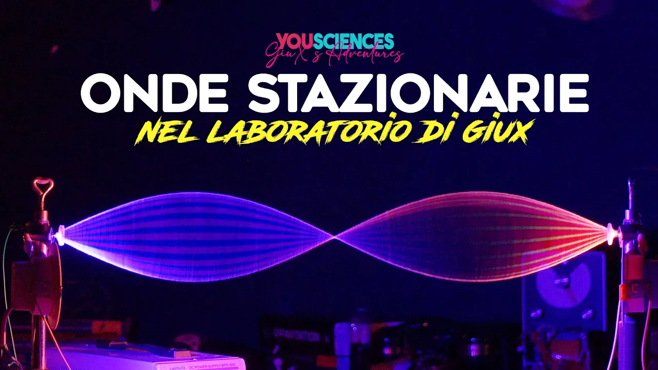
Generare delle ONDE STAZIONARIE luminose e Scoprire come una RISONANZA Separa la LUCE (4K) GiuXlab
21.3K
Standing waves are stationary wave patterns formed by the interference of two traveling waves—one progressive and one regressive—moving in opposite directions. These waves create alternating regions of maximum oscillation called antinodes (ventri) and points of zero oscillation called nodes. The phase relationship between waves determines amplitude: in-phase waves double amplitude, counter-phase waves cancel each other. Standing waves are confined within boundaries created by synchronized motors. Resonance occurs when systems vibrate at natural frequencies, producing maximum amplitude. Harmonics are integer multiples of the fundamental frequency: the second harmonic has wavelength equal to the distance between fixed points, while the third harmonic has wavelength equal to two-thirds of that distance. The number of antinodes and nodes increases with higher harmonics. Wave velocity depends on motor tension and medium density—higher tension increases velocity, while denser materials reduce it.
Click to watch →

Complete Waves Class 11 (Day 14) | "FREE" NEET 2023 Crash Course | NEET Physics | Sachin Sir
88.4K
Standing waves form when two identical waves traveling in opposite directions interfere. Nodes are points of zero amplitude where destructive interference occurs. Antinodes are points of maximum amplitude where constructive interference occurs. The distance between consecutive nodes is λ/2, and between consecutive antinodes is also λ/2. The distance between a node and adjacent antinode is λ/4.
Click to watch →
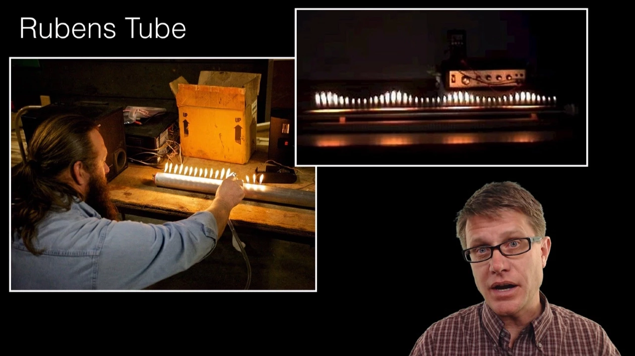
Standing Waves
189.8K
Standing waves are stationary wave patterns formed by the reflection and interference of traveling waves, characterized by nodes (points of no movement due to destructive interference) and antinodes (points of maximum movement due to constructive interference); they occur in systems with fixed boundaries such as strings fixed at both ends (guitar strings), tubes closed at one end (vuvuzelas), and tubes open at both ends (flutes), where different harmonics produce different pitches based on the wavelength relationships that satisfy the boundary conditions.
Click to watch →
MHT CET CRASH Course | One shot ch 6 Superposition of wave class 12 Revision for MHT CET #nie
101.4K
Nodes are points of zero displacement in a stationary wave where destructive interference occurs continuously. Antinodes are points of maximum displacement where constructive interference occurs continuously. The distance between consecutive nodes equals half the wavelength. For a pipe closed at one end, only odd harmonics are produced. For a pipe open at both ends, all harmonics are produced.
Click to watch →
Deep Dive
Basic principles of geometric optics, specifically how light refracts when passing through mediums of varying densities (refractive index).
NDA Physics🔥Optics Part 1|😱Zero to Hero| Kapil Sir
27.7K
Refraction is the bending of light when passing between media of different optical densities. Dense media have higher optical density, rare media have lower. Light bends toward the normal when entering dense media and away from the normal when entering rare media. Snell's Law states that sin(i)/sin(r) = constant for a given pair of media, where i is the angle of incidence and r is the angle of refraction. This constant is the refractive index of the second medium with respect to the first. Refractive index (n) is the ratio of the speed of light in vacuum to the speed of light in the medium: n = c/v. It is also called optical density and has no units. Refractive index is inversely proportional to light speed in the medium. Higher refractive index means lower light speed. Relative refractive index between two media: n_2/1 = n_2/n_1 = v_1/v_2. Absolute refractive index is with respect to vacuum. Refractive index decreases with increasing wavelength, so blue light has higher refractive index than red light. Light speed increases when passing from denser to rarer media and decreases when passing from rarer to denser media.
Click to watch →

فوق المهم |علوم الصف الثاني الاعدادي الترم التاني درس انعكاس وانكسار الضوء علوم تانيه اعدادي
113.4K
Light refraction is the bending of light when passing between transparent media of different optical densities. Unlike reflection (bouncing back), refraction involves changing the light's path. Optical density is a medium's ability to bend light, with an inverse relationship to light speed: higher density means slower light. Glass has highest optical density, followed by water, then air. Light refracts only when striking the boundary at an angle (not perpendicularly). The absolute refractive index (n) is the ratio of light speed in vacuum to light speed in a medium: n = c/v. It is always greater than 1 because light travels fastest in vacuum. It has no units because it is a ratio of two speeds. The relative refractive index of one medium with respect to another is n_relative = n1/n2. Higher optical density corresponds to higher refractive index. These relationships are fundamental to understanding optical properties of materials.
Click to watch →

مراجعة علوم الوحدة التانيه الصف الثانى الاعدادى الترم الثانى
55.5K
Refraction is the bending of light when passing between media of different optical densities. Optical density determines light speed: solids highest, liquids intermediate, gases lowest. When light enters higher optical density, it bends toward the normal (angle of refraction < angle of incidence). When light exits higher optical density, it bends away from the normal (angle of refraction > angle of incidence). The absolute refractive index is n = c/v, where c is speed in vacuum and v is speed in medium. The index is always greater than 1.
Click to watch →

Geometrical optics
136
Refraction is the bending of light when it passes from one medium to another of different optical density, caused by a change in light speed. Optical density measures a medium's refracting power—higher density means slower light speed. The refractive index (n) is calculated as n = c/v, where c is the speed of light in vacuum (3 × 10^8 m/s) and v is the speed in the material. Light bends toward the normal when entering a denser medium (air to glass) and away from the normal when entering a less dense medium (glass to air). The frequency of light remains constant during refraction, though speed and wavelength change.
Click to watch →

REFRAÇÃO da LUZ e REFLEXÃO TOTAL - ÓPTICA - #LIVETODODIA2020 - AULA 61
5.6K
Refraction is the bending of light when passing between media with different optical densities. Light bends toward the normal when entering a more refractive medium and away from the normal when entering a less refractive medium. The refractive index (n) is defined as n = c/v, where c is light speed in vacuum and v is speed in the medium. Vacuum has n=1, air ≈1, water ≈1.33, glass ≈1.5, and diamond ≈2.42. Snell's Law (n₁sinθ₁ = n₂sinθ₂) governs all refraction phenomena. The relative refractive index of medium A with respect to medium B is n_A/n_B.
Click to watch →
Deep Dive
The concept of acoustic radiation pressure and how mechanical waves can exert physical force on matter.
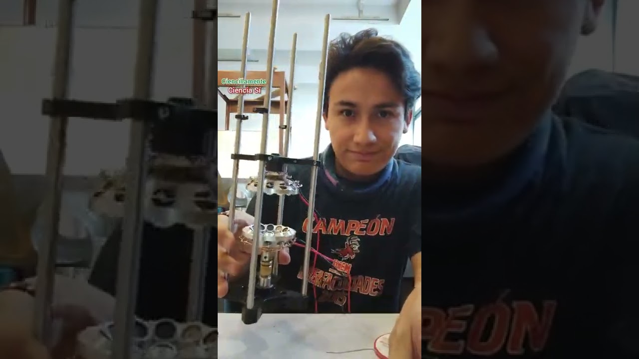
Construyendo un LEVITADOR ACÚSTICO
5.4K
Sound is a mechanical wave that travels through a medium by creating pressure variations. As a mechanical wave, sound carries momentum and can exert pressure on particles through radiation pressure. This pressure can push and move other particles in the medium, demonstrating how sound energy can physically interact with matter.
Click to watch →

Markus Aspelmeyer plenary talk Photonics West 2013: Quantum Optomechanics
3.7K
Radiation pressure is a fundamental physical phenomenon where electromagnetic radiation exerts mechanical force on matter. First conjectured by Kepler to explain comet tail orientation, it was unambiguously demonstrated in 1901 by Lebedev and Nichols/Henley. Radiation pressure underlies many modern optical technologies including laser trapping and manipulation of atoms (the basis of modern atomic physics) and optical tweezing (an important tool in biological physics). A single photon has negligible effect on macroscopic mirrors, but when photons bounce multiple times within an optical cavity, the cumulative radiation pressure becomes significant enough to influence mechanical systems substantially.
Click to watch →

2010) RECLAMAÇÃO - CJ BORGE - ISLAND EFFECT THEORY OF GRAVITATION
1K
Waves, despite having no mass, can exert force on matter because they transport energy and linear momentum. When waves are absorbed by matter, the transferred energy causes heating, and the absorbed momentum creates a pushing effect. This phenomenon is known as radiation pressure, where electromagnetic radiation (which has no mass) exerts pressure on surfaces. Pressure is defined as force divided by area, and this principle explains how waves can push matter.
Click to watch →
Matter Waves | Radiation Pressure | Physics | JEE 2026 | Siva Sir
1.5K
Matter waves are probability disturbances associated with particles that transfer energy. Radiation pressure is the force exerted by light on surfaces due to photon momentum transfer. Despite photons having zero rest mass, they carry momentum p = h/λ, enabling light to exert mechanical pressure on objects. This principle underlies technologies like solar sails.
Click to watch →

Давление звукового излучения
84.2K
Acoustic radiation pressure is a phenomenon where sound waves exert a steady force on objects. The video demonstrates this using an ultrasonic transducer at 40 kHz, which causes a lightweight polystyrene plate to deflect. Wilhelm Albert discovered this in 1903, a student of Pyotr Lebedev. The demonstration shows that while sound waves oscillate 40,000 times per second, the plate experiences a constant force causing steady deflection. Radiation pressure is approximately 0.1 Pascal, about one million times smaller than atmospheric pressure. A common misconception is that radiation pressure might be caused by an air current, but experiments with a fabric screen showed the effect remained unchanged. Theoretical analysis reveals that radiation pressure arises from momentum transfer in wave packets, where the pressure equals air density multiplied by the second-order velocity and the speed of sound. In stationary sound fields, air slowly moves away from the source toward the target surface, and when a horn prevents this return flow, radiation pressure persists.
Click to watch →
Prerequisite Knowledge
- Concept 01The fundamental physics of sound as longitudinal pressure waves, including compressions and rarefactions.
- Concept 02The mechanics of wave interference, resonance, and the creation of standing waves with nodes and antinodes.
- Concept 03Basic principles of geometric optics, specifically how light refracts when passing through mediums of varying densities (refractive index).
- Concept 04The concept of acoustic radiation pressure and how mechanical waves can exert physical force on matter.
Subsequent Learning
- Step 01Dynamic 3D manipulation of objects using phased array acoustic levitation (acoustic holography).
- Step 02Real-world applications of acoustic trapping in microfluidics, such as contact-free handling of biological cells and chemical droplets.
- Step 03Containerless processing in material science and chemistry to study crystallization and high-temperature reactions without wall contamination.
- Step 04Advanced Schlieren and Shadowgraphy optical setups used for visualizing supersonic airflow and thermal gradients in aerospace engineering.
- Step 05Mathematical modeling of acoustic trapping forces, specifically using Gor'kov's potential theory.
Acoustic Levitation
Visualizing Waves
Acoustic Levitation
0:04Playing Section
- 1
Demonstrates levitating objects using high-frequency sound waves.
- 2
Explains standing wave formation between speaker and reflector.
- 3
Shows how pressure zones suspend small objects in mid-air.
Limitations of Standing-Wave Levitation and the Near-Field Alternative
While standing-wave acoustic levitation successfully suspends lightweight particles at nodal points, it has severe payload limitations and is highly susceptible to instability from acoustic streaming—vortex air currents that can disrupt and eject trapped objects. To overcome these limitations, researchers utilize Near-Field Acoustic Levitation (NFAL). Instead of relying on standing waves and reflectors, NFAL exploits the 'squeeze film' gas pressure generated between a high-frequency radiating surface and a closely positioned flat object. This alternative mechanism can support much heavier payloads (up to several kilograms) and provides greater stability, making it far more suitable than standing-wave systems for industrial applications like handling fragile silicon wafers and glass panels.
Deep Dive
Dynamic 3D manipulation of objects using phased array acoustic levitation (acoustic holography).
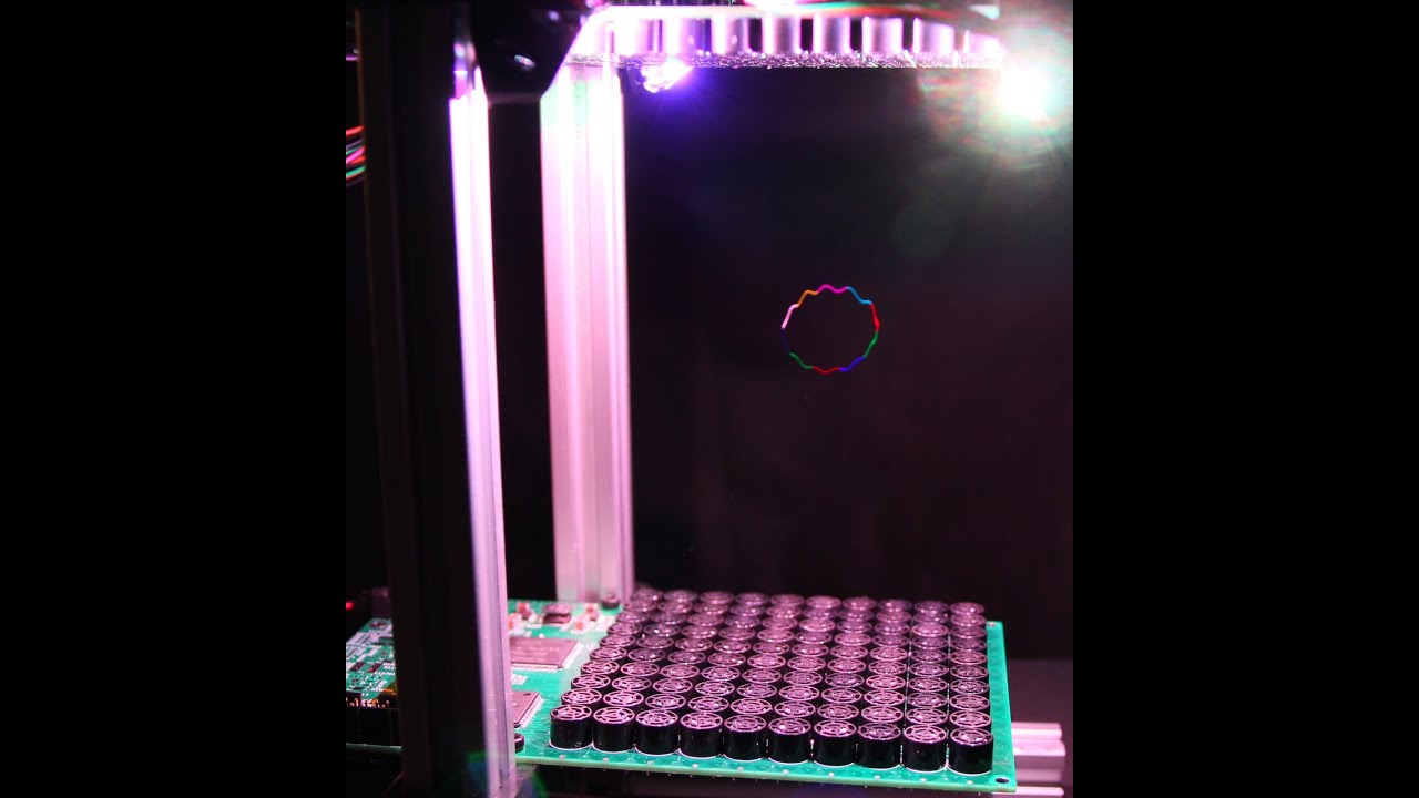
Hologram V0.1?
15.2K
By using phased arrays of ultrasonic transducers emitting 40 kHz sound waves, it is possible to create standing waves in 3D space that can levitate small objects like foam balls and move them rapidly to form floating images; the system calculates individual transducer phases based on the distance from each transducer to the desired focus point, using the wave number to convert distance into phase shifts, enabling real-time image rendering and animation in mid-air.
Click to watch →
![Three-Dimensional Mid-Air Acoustic Manipulation [Acoustic Levitation] (2014-)](https://i.ytimg.com/vi/odJxJRAxdFU/maxresdefault.jpg)
Three-Dimensional Mid-Air Acoustic Manipulation [Acoustic Levitation] (2014-)
4M
This study presents a method for three-dimensional mid-air acoustic manipulation of millimetre-sized particles using ultrasonic phased arrays. Unlike previous acoustic levitation techniques that relied on ultrasound beams aligned parallel to gravity, enabling only one-dimensional movement along a fixed axis, this system generates localized ultrasonic standing waves at arbitrary positions in 3D space. The manipulation is achieved by opposing ultrasonic phased arrays that create and move standing waves in any direction, not limited to vertical alignment. The force acting toward the center of the ultrasound beam is harnessed to position and move objects in all three spatial dimensions. The researchers experimentally confirmed that various materials can be levitated and manipulated using this approach. The technology builds upon the known principle that ultrasound standing waves can suspend small particles at their sound pressure nodes, but extends it by introducing spatial control through phased array technology. The system allows for dynamic, arbitrary positioning of levitated objects without physical contact. The work was published in arXiv in December 2013 under the title “Three-dimensional Mid-air Acoustic Manipulation by Ultrasonic Phased Arrays” and is associated with the University of Tokyo and Nagoya Institute of Technology. The method represents a significant advancement in non-contact manipulation of small objects using acoustic forces.
Click to watch →
كيف نرفع الأجسام بالصوت؟ | سحر الفيزياء الذي لم تره من قبل
73.8K
Acoustic levitation requires two essential devices: a transducer that converts electrical energy into mechanical sound vibrations, and a reflector that bounces sound waves back toward the source. When these waves interfere, they create standing waves with nodes (points of minimal pressure) and antinodes (points of maximum pressure). Objects are placed at nodes while surrounded by high-pressure antinodes, creating a stable levitation zone. The distance between transducer and reflector must be precisely calculated as an integer multiple of half the wavelength to create multiple levitation points. This technology has significant industrial applications: in semiconductor manufacturing, it prevents contamination by handling materials without physical contact; in chemistry, it allows samples to be analyzed without reacting with containers; and in foam research, it enables studies free from gravitational effects.
Click to watch →

波動で物体を浮かせる原理 #音響浮揚 #実験 #ホログラム
181.6K
Acoustic levitation works by creating standing waves through the interference of sound waves from a source and a reflector, where the distance between them maintains a multiple of half the wavelength, generating high-pressure nodes that can suspend objects in mid-air; this technology has evolved from simple 2D suspension to 3D manipulation and holographic displays.
Click to watch →
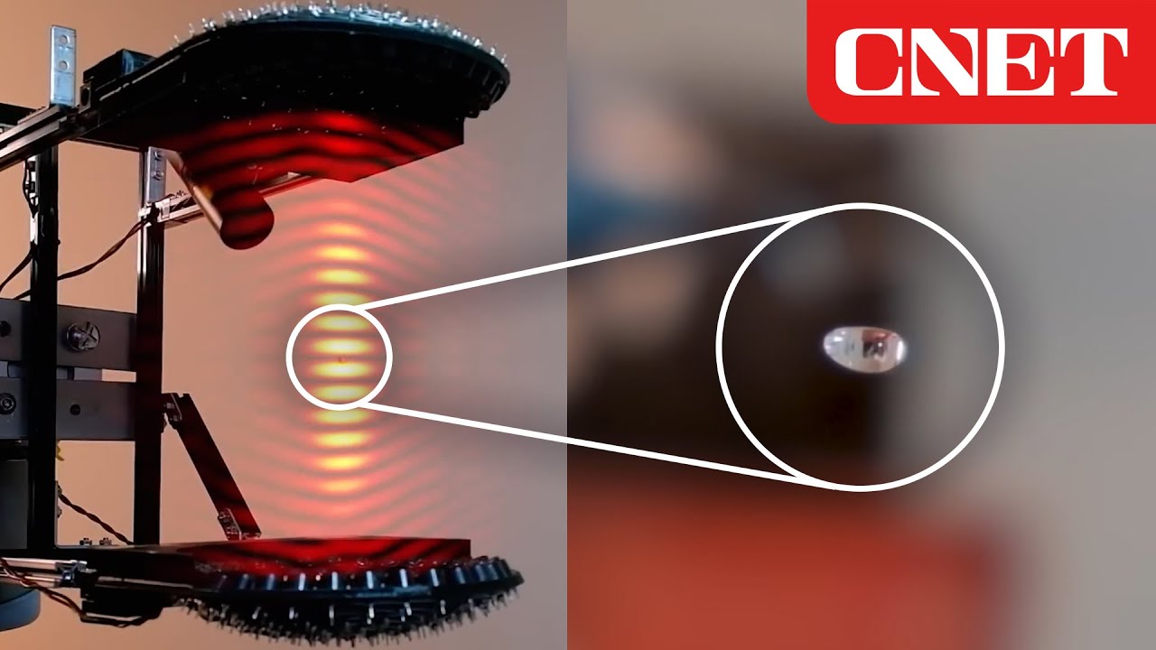
Defying Gravity: LeviPrint Uses Sound Waves to Levitate Objects
254.6K
Acoustic levitation uses high-frequency sound waves (approximately double the highest human hearing frequency) to create standing wave patterns that trap and manipulate objects in mid-air, enabling touch-free assembly of complex structures by positioning objects in low-amplitude regions of the interference pattern; this technology offers advantages over traditional methods including reduced cross-contamination, versatility in handling different object types (spheres, sticks, glue droplets), and ability to move parts through tight spaces, making it promising for biomedical applications and precision manufacturing of small components like watches and camera parts.
Click to watch →
Deep Dive
Real-world applications of acoustic trapping in microfluidics, such as contact-free handling of biological cells and chemical droplets.

Terasaki Talks Presents: “Manipulation of Micro/Nano Particles Using Acoustic Waves”, Present...
316
This section explores advanced applications of acoustic manipulation technology. Endoskeletal droplets containing solid particles within liquid droplets offer potential for photoacoustic imaging applications. Researchers developed microfluidic devices to generate uniform endoskeletal droplets with precise size and composition control. Acoustic fields induce unexpected clustering behavior and internal disk alignment, where competing primary (upward) and secondary (sideways) acoustic forces determine orientation depending on frequency. Single droplets align horizontally; two-droplet clusters show intermediate angles; three or more droplets exhibit systematic frequency-dependent orientation changes. This enables frequency-controlled light shutter applications and manipulation of organized cell clusters. For model organism research, acoustic manipulation addresses challenges in handling C. elegans worms: contactless trapping, reversible immobilization in 15-20 seconds versus irreversible heat-based methods, and fluid streaming to modulate swimming exercise intensity for studying Parkinson's disease effects on dopaminergic neurons.
Click to watch →

Lecture on Acoustofluidics
1.5K
Acoustic trapping concentrates particles or cells at specific locations using localized acoustic fields. Unlike acoustic separation, trapping holds particles against fluid flow. Cells trapped acoustically can be cultured successfully without damage, demonstrating that the acoustic forces used are gentle enough for biological applications. This enables long-term cell observation, drug screening, and cell-cell interaction studies in controlled microenvironments.
Click to watch →

Steven Cummer | Sept 6 | ME Departmental Seminar
231
Acoustic tweezers use radiation forces from scattered acoustic waves to trap and manipulate particles in fluids without physical contact. When particles scatter acoustic waves, the resulting force can hold them in specific locations. Standing wave patterns created by multiple transducers create stable trapping points where particles accumulate. The acoustic contrast factor (depending on particle and fluid densities/bulk moduli) determines whether particles are attracted to pressure maxima or minima. This technology has biomedical applications for cell handling, sorting, and assembly.
Click to watch →

Tweezers of sound can pick objects up without physical contact | Acoustic trapping
3.2K
Researchers at Tokyo Metropolitan University have developed mid-air acoustic tweezers using a hemispherical array of ultrasound transducers that can trap and manipulate millimeter-sized particles without physical contact, offering a versatile alternative to laser-based optical trapping by utilizing sound waves instead of light, which can work across a wider range of particle sizes and materials.
Click to watch →

ME Seminar Series WN 2023: Tony Jun Huang
444
Acoustic fluidics enables unprecedented control of cellular interactions and large-scale biological processing. For cell communication studies, precise intercellular distance control (from 50 microns to contact) reveals signaling dynamics, demonstrating that 3-micron separation prevents molecular transfer. HARMAN (Harmonic Acoustics for Non-Contact Dynamic Selective Manipulation) creates programmable 1D, 2D, and 3D cell patterns with virtual acoustic hands, enabling complex tissue engineering constructs. Digital acoustic fluidics automates droplet operations including generation, splitting, and merging at programmable rates. For clinical applications, the technology processes blood at >100 mL/min, separating platelets from red blood cells with superior preservation of platelet function. Three-dimensional zebrafish manipulation enables whole-organ imaging without sacrifice. These capabilities span from single-cell precision to industrial-scale processing, demonstrating acoustic fluidics' transformative potential across basic research and clinical translation.
Click to watch →
Deep Dive
Containerless processing in material science and chemistry to study crystallization and high-temperature reactions without wall contamination.

Minimum Duration Flameballs | STS-83 | End of Mission Episode 23
687
TEMPUS electromagnetic containerless processing suspends metal alloys using electromagnetic levitation, eliminating container contamination. Experiments study undercooled metallic melts, metallic glasses based on zirconium alloys, and quasicrystals with poly-tetrahedral short-range order. Oscillating drop techniques measure surface tension of undercooled liquids. Dendrite morphological stability examines branching structures formed during solidification. Nucleation studies investigate solidification velocity under different flow regimes. Alloy undercooling experiments use video and temperature measurements. These techniques enable processing of materials impossible on Earth, producing metastable phases and unique microstructures with novel properties.
Click to watch →

AFTherMat Webinaire#4 Emmanuel de BILBAO, Emmanuel VERON, Vincent SAROU-KANIAN 20221201
146
Aerodynamic levitation enables containerless synthesis of advanced materials by allowing samples to reach very high temperatures without container contact. This eliminates heterogeneous crystallization and contamination. The technique is particularly valuable for synthesizing transparent ceramics and glasses, as well as for studying metastable phases. For YAG (Y3Al5O12), levitation enables non-stoichiometry levels 10 times higher than conventional methods (0.3 vs 0.03), allowing modification of crystal field environments for optical property control.
Click to watch →

Enhance Success of Crystallization: Choosing Crystallization Method
1.1K
Containerless crystallization uses a layer of vaseline (high-density oil) beneath paraffin oil, with drops dispensed between them. Since the drop doesn't touch container walls, nucleation is reduced. This setup produces larger, fewer crystals compared to standard microbatch. It is useful for optimization when fewer, larger crystals are desired, though it is more complex than standard screening and typically done manually or robotically.
Click to watch →

STS-65 Post Flight Presentation
1.5K
Containerless processing techniques allow scientists to heat and manipulate materials without physical contact with container walls. Using electromagnetic levitation furnaces, small samples can be heated to melting temperatures and then re-solidified without contamination from container surfaces. This approach produces purer materials with more uniform properties compared to traditional container-based methods. The technique is particularly valuable for studying material behavior under controlled conditions and developing advanced materials for technological applications.
Click to watch →

A One-week Online FDP on “Advanced Materials processing and Characterization Methods”.
386
The floating zone method grows crystals without any container by using electromagnetic induction to levitate and melt a rod of the material. Two rods (feed rod and seed rod) are positioned parallel to each other, and an induction coil heats the region between them, creating a molten zone that floats between the solid portions. The molten zone is slowly translated along the rods, causing solidification and crystal growth. This containerless approach eliminates contamination from crucibles and is particularly suitable for growing high-purity crystals of refractory materials. Large crystals up to 10 cm in length can be produced using this technique.
Click to watch →
Deep Dive
Advanced Schlieren and Shadowgraphy optical setups used for visualizing supersonic airflow and thermal gradients in aerospace engineering.
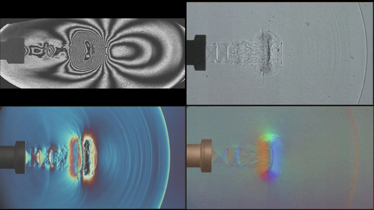
Schlieren Imaging Systems for Flow Visualization | UNSW Canberra
44.8K
Schlieren imaging systems make invisible density variations in fluids visible by exploiting the fact that light travels at different speeds through media of different densities; these systems use optical setups to reveal shock waves, wakes, and other flow phenomena that are otherwise imperceptible to the naked eye, with applications ranging from supersonic aerodynamics to everyday phenomena like opening fizzy drinks or popping balloons.
Click to watch →
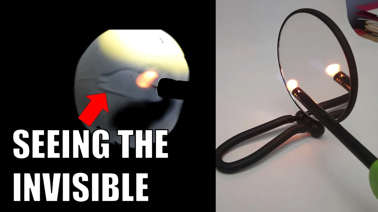
DIY Schlieren Imaging and Shadowgraphy | Science Project
4.6K
Shadowgraphy and schlieren imaging are optical techniques that visualize invisible air currents and density variations by detecting how light bends through regions of different air density. These methods use a point light source reflected off a concave spherical mirror toward a camera, revealing phenomena invisible to the naked eye such as fuel jets before ignition, air movement around flames, and temperature-induced density changes. The complete home setup requires minimal equipment: a camera (including cell phones), a flashlight modified into a point light source, and a concave mirror (makeup mirrors work effectively). Key steps include finding the focal point by moving a black paper toward the mirror until the light spot becomes most focused, then positioning the light source at twice the focal length. Optical alignment requires careful adjustment so reflected light enters the camera lens, with exposure settings adjusted to prevent overexposure. Shadowgraphy captures basic density variations, while schlieren imaging adds a light block that blocks exactly half the focused light, dramatically increasing contrast to reveal subtler phenomena like cold air around ice cubes. Image quality depends on both component quality and alignment precision—small adjustments of millimeters or degrees significantly impact results. Starting with simple setups and progressively upgrading components allows exploration of increasingly subtle density variations.
Click to watch →
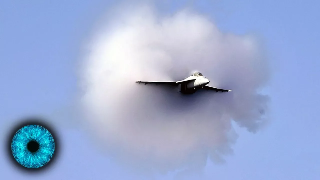
Fliegen wir bald mit Überschall? - Clixoom Science & Fiction
36.2K
NASA has developed schlieren imaging technology, originally invented over 150 years ago by a German physicist to visualize invisible air density changes, which now enables engineers to design quieter supersonic aircraft by making shock waves visible; this breakthrough could allow commercial supersonic travel between continents in approximately three hours without the disruptive sonic boom that previously made such flights impractical over populated areas.
Click to watch →
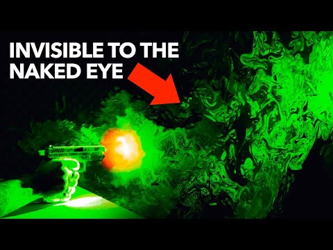
The Science Behind Dogs' Incredible Sense Of Smell
6.8M
Flow visualization reveals invisible air movements through optical techniques. Schlieren imaging detects density variations by observing light refraction changes using mirrors and razor blades at focal points. Shadowgraph casting shadows of density variations onto walls provides simpler visualization. These methods visualize supersonic bullet bow shocks, where sin(θ) = speed of sound / bullet speed, enabling Mach number calculation. The darkness of shock images correlates with sound intensity, as louder firearms create more pronounced pressure changes. These techniques also reveal invisible gunshot residue plumes and human thermal plumes containing skin cells, demonstrating how optical methods make invisible phenomena observable for scientific analysis.
Click to watch →
Schmidt Cassegrain Telescope (SCT) Modification
16.6K
Stagnant air in front of the primary mirror creates thermal gradients that degrade optical seeing conditions, causing distorted star images even when properly focused. Installing fans and baffles forces turbulent airflow over the mirror surface, breaking up these static air layers. Qualitative observations show that after running the fan system for about an hour, defocused star images transition from showing dynamic optical turbulence (waves passing through the doughnut pattern) to appearing relatively uniform, indicating improved seeing conditions in the air column just in front of the mirror.
Click to watch →
Deep Dive
Mathematical modeling of acoustic trapping forces, specifically using Gor'kov's potential theory.

Del laboratorio al sonido: cómo separamos células con ultrasonido
342
When an acoustic field is applied to cells in a fluid, a radiation force is generated that moves particles toward regions of different pressure (nodes or antinodes). Gorkov's theory (1960) describes how this force depends on particle size, wavelength, acoustic energy, and the acoustic contrast factor. The acoustic contrast factor determines whether particles move toward nodes (regions of minimum pressure) or antinodes (regions of maximum pressure) based on their physical properties relative to the surrounding fluid.
Click to watch →
The Mind-Blowing Science Behind Levitation: Can We Defy Gravity?
416
Fundamental mathematical theory for acoustic levitation, developed by Gor'kov, states that the particle being trapped is a spherical asymmetry. However, this asymmetry alters the force and torque applied to an object during levitation and shifts the site of the trapping. This theory provides the mathematical foundation for understanding how sound waves can precisely manipulate and control small objects in mid-air.
Click to watch →
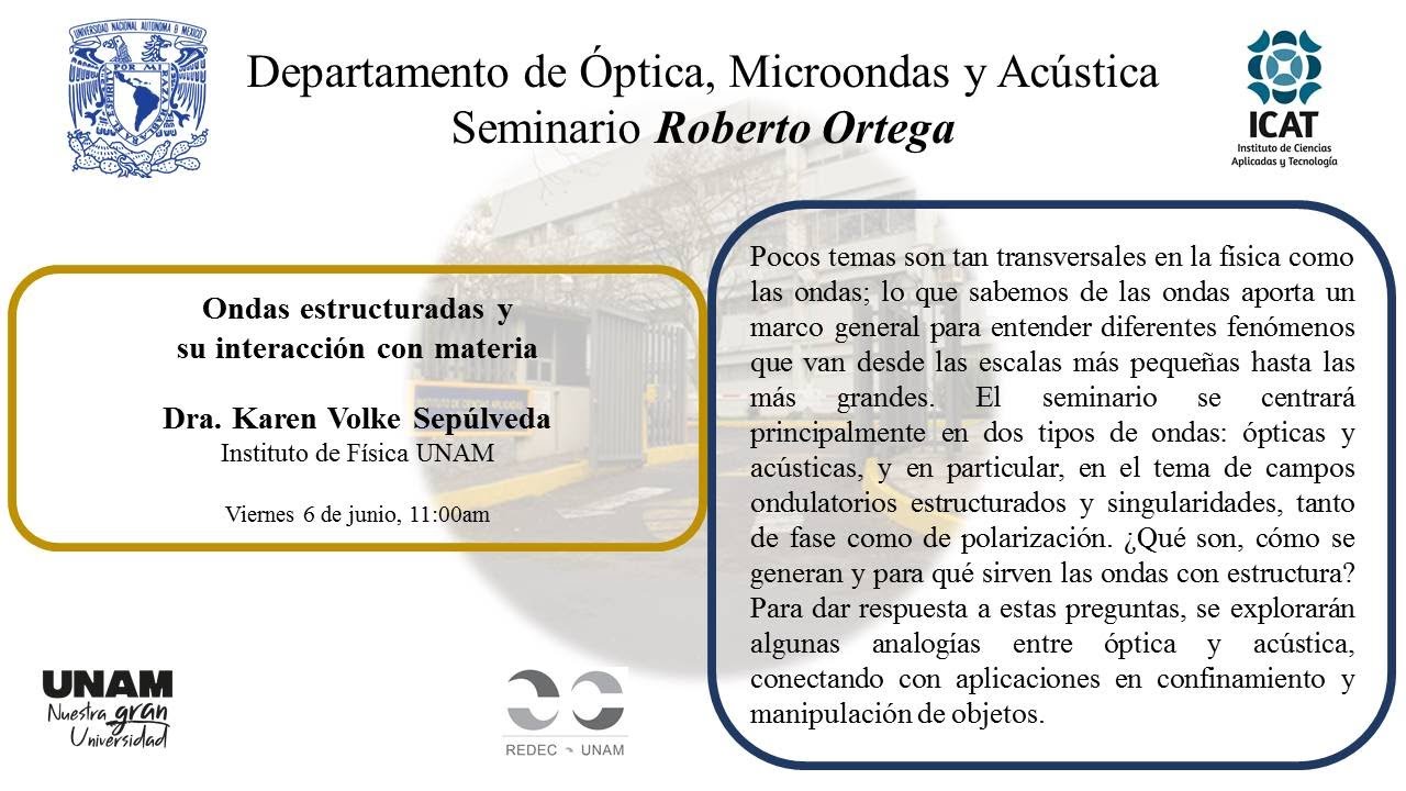
Ondas estructuradas y su interacción con materia
114
Radiation traps enable non-contact manipulation of matter across scales from atomic to millimeter levels. Optical traps operate in fluids using visible light, while acoustic traps work in air using ultrasonic frequencies (1-20 MHz). Radiation forces arise from momentum exchange: optical forces use the Maxwell stress tensor, acoustic forces use the Brillouin tensor. In the Rayleigh regime, optical forces depend on refractive index contrast, while acoustic forces include terms for both particle velocity and pressure. The Gorkov potential describes acoustic trapping, but the generalized Lorenz-Mie theory (developed for optics in 1988, adapted to acoustics in 2013) is required for arbitrary particle sizes. Single-beam acoustic traps were only successfully demonstrated in 2016—approximately 30 years after optical tweezers—because acoustic particles typically migrate toward pressure nodes rather than antinodes. Standing wave levitation traps use stationary acoustic waves where pressure nodes coincide with displacement antinodes, enabling non-contact positioning of matter for chemical analysis, microgravity simulation, and delicate sample manipulation. Higher-order modes in acoustic cavities expand trapping capabilities beyond fundamental standing waves. By controlling phase in different quadrants of spherical transducer arrays, researchers generate cosoidal and sinusoidal modes with increasing complexity. Mode order m determines the number of lobes in the pressure distribution (2m lobes). These higher-order modes enable trapping of larger particles, irregularly shaped objects, and particles in different regions of the acoustic field. Structured wave approaches increase trapping versatility, enabling manipulation across unprecedented size ranges and geometries.
Click to watch →

Perpetual Computing: Technologies for Banishing Batteries - Dr. Joshua Smith
196
Acoustic levitation uses standing ultrasound waves to create acoustic radiation forces that can suspend objects in mid-air. The Gorkov potential describes the acoustic potential energy landscape created by these standing waves, with minima (nodes) and maxima (antinodes) where particles tend to collect. Most objects are attracted to pressure nodes. To lift objects off a surface, mirror image methods from electromagnetics can model how rigid boundaries affect acoustic fields, allowing engineers to design transducer arrays that create upward-pointing potential minima above the surface.
Click to watch →

TastyFloats: A Contactless Food Delivery System
272
The acoustic force required to levitate a food morsel depends on several factors: (1) Radius of the particle being levitated, (2) Compressibility of the levitated morsel in air, (3) Pressure and velocity of air due to emitted acoustic waves, and (4) Ratio of density between the food and air. Under the assumption of one-dimensional sine standing waves and assuming food density is much greater than air, the minimum acoustic force depends on the density of the levitated food morsel, wave number, and speed of sound in air.
Click to watch →
Acoustic Levitation
Visualizing Waves
Acoustic Levitation
0:04- 1
Demonstrates levitating objects using high-frequency sound waves.
- 2
Explains standing wave formation between speaker and reflector.
- 3
Shows how pressure zones suspend small objects in mid-air.
Limitations of Standing-Wave Levitation and the Near-Field Alternative
While standing-wave acoustic levitation successfully suspends lightweight particles at nodal points, it has severe payload limitations and is highly susceptible to instability from acoustic streaming—vortex air currents that can disrupt and eject trapped objects. To overcome these limitations, researchers utilize Near-Field Acoustic Levitation (NFAL). Instead of relying on standing waves and reflectors, NFAL exploits the 'squeeze film' gas pressure generated between a high-frequency radiating surface and a closely positioned flat object. This alternative mechanism can support much heavier payloads (up to several kilograms) and provides greater stability, making it far more suitable than standing-wave systems for industrial applications like handling fragile silicon wafers and glass panels.
The fundamental physics of sound as longitudinal pressure waves, including compressions and rarefactions.
The mechanics of wave interference, resonance, and the creation of standing waves with nodes and antinodes.
Basic principles of geometric optics, specifically how light refracts when passing through mediums of varying densities (refractive index).
The concept of acoustic radiation pressure and how mechanical waves can exert physical force on matter.
Dynamic 3D manipulation of objects using phased array acoustic levitation (acoustic holography).
Real-world applications of acoustic trapping in microfluidics, such as contact-free handling of biological cells and chemical droplets.
Containerless processing in material science and chemistry to study crystallization and high-temperature reactions without wall contamination.
Advanced Schlieren and Shadowgraphy optical setups used for visualizing supersonic airflow and thermal gradients in aerospace engineering.
Mathematical modeling of acoustic trapping forces, specifically using Gor'kov's potential theory.
2.8M views82.3Klikes4:34@NatSciDemosOriginal Release: 2017-02-23
I'd like to show you an example of levitating small objects with sound waves.
Let me just remind you how a loudspeaker works: It's just a diaphragm that...repeatedly pushes on the air, producing high pressure waves that move away. And that's what we have here with this little gizmo, it does the same thing except it's at a very high frequency-- twenty-eight thousand Hertz, which is way above our human hearing range.
So these sound waves move upward, and up above I have a glass plate, which is going to reflect the sound back down again. When the distance between the glass plate and the loudspeaker is just right, then those sound waves that are moving down will interfere constructively with the sound waves coming up, and give us regions of high pressure and low pressure, which don't move around they stay in one spot.
It's in those high pressure zones that I'm going to try to levitate a small ball.
So let me turn on the power, and even though I can't hear it, I'm still going to use ear protection.
As I said before, the distance between the reflector and the loudspeaker is just right. If I change it--which I'm going to do--you'll see that this standing wave disappears, and the balls are no longer suspended there.
We've now set up the little loudspeaker and the reflector in front of this mirror, which is part of our Schlieren optics setup. The purpose of that is to be able to actually see where there are regions of high pressure and low pressure in the air, especially the air between the reflector and the loudspeaker. So let me turn up the volume, and before I do that, I will put on my protective hearing.
And if I adjust the height of the reflector, there's a point at which you see bands of white light and dark.
This is the standing wave, and it only happens when the distance between the reflector and the speaker is some multiple of a half a wavelength.
So every single one of those bands is half wavelength! If I go up a little higher, then it disappears again. But if I continue to go higher, then it will come back when I'm at another... multiple of a half wavelength away.
Now, it's in these bands that I'm going to place the little balls.
You can see the little ball settles down where there's a bright band, and that is the high-pressure area.
And I know it's high pressure, because you see there's a white band right next to the reflector, which is where the highest pressure will be?
If I again change the height, the standing wave goes away, and the little balls will fall down.
Up Next

9:24
How to Build an Acoustic Levitator: Physics of Sound Levitation
@physicsgirl
689.7K views•2017-12-14

12:53
21cm Hyperfine Transition in Neutral Hydrogen: Radio Astronomy Basics
@AaronRobertParsons
12.4K views•2011-10-13

32:32
NMR Spin Physics I: Zeeman Effect, Resonance Condition & Larmor Frequency
@nptel-indianinstituteofsci8064
2.3K views•2024-01-17

27:14
Entropy and the Second Law of Thermodynamics Explained
@veritasium
27.5M views•2023-07-01
Related Study Plans & Knowledge Roadmaps
Structured learning paths in Physics
physics
Nuclear Physics (Decay, Fission & Reactors)
01Atomic Structure and the Binding Force
02Radioactive Decay and Half-Life
03Nuclear Fission Mechanics and Chain Reactions
+ 2 more learning modules
12h5 modules
Explore Roadmap
physics
Soft Matter (Polymers, Colloids & Rheology)
01Foundations of Soft Matter & Thermal Forces
02Polymer Physics and Macromolecules
03Colloids, Surfactants, and Self-Assembly
+ 2 more learning modules
38h5 modules
Explore Roadmap
physics
Analytical Mechanics: Lagrangian & Hamiltonian
01Mathematical Foundations: Calculus of Variations
02From Newtonian Mechanics to Constraint Dynamics
03The Principle of Least Action & Lagrangian Mechanics
+ 3 more learning modules
28h6 modules
Explore Roadmap
physics
General Relativity (Spacetime & Cosmology)
01Foundations of Relativity: Special Relativity
02The Geometry of Spacetime: Equivalence Principle & Curvature
03Einstein's Field Equations: The Mathematics of Gravity
+ 2 more learning modules
55h5 modules
Explore Roadmap