


![Piezoelectricity [Year-1]](https://i.ytimg.com/vi/urJN4aPs4oE/maxresdefault.jpg)



























To measure the resonant frequency of an ultrasonic transducer, connect a sine wave signal generator to the transducer with a 100 ohm resistor in series, using an oscilloscope to monitor voltage and current; the resonant frequency occurs where current draw is maximum and current and voltage are in phase. When designing a horn, calculate the half-wavelength using the speed of sound in the material (approximately 5,800 m/s for aluminum) divided by the resonant frequency, then iteratively shorten the horn while measuring resonance until it matches the bare transducer frequency. Critical considerations include: always attach the intended tip or tool before tuning, mount the horn at a node point to minimize damping, avoid using square wave excitation which creates false resonance indications from harmonics, and note that temperature slightly decreases resonant frequency.
Ultrasonic Transducers: Resonant Frequency Measurement and Horn Design
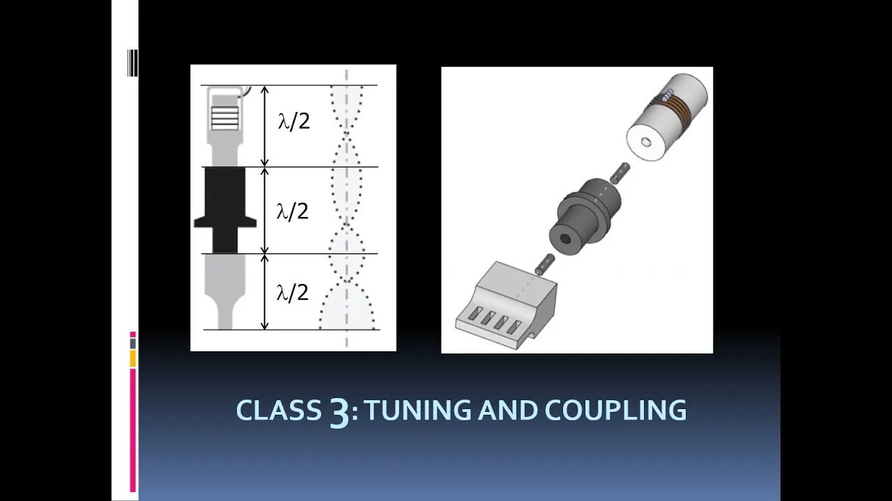
Added:hello in this video I'm going to show how I measure the resonant frequency of an ultrasonic transducer and also show how to correctly machine and tune a suitable horn for screwing onto the end of it so this is the circuit that that I'm using I've got a sinewave signal generator putting out a few volts and this is connected to both the ultrasonic transducer and 100 ohm resistor in series this resistor will allow us to measure the current flowing through the circuit an oscilloscope is connected to uh channel one is connected to the signal generator output that tells us the voltage applied and channel 2 is connected to the 100 ohm resistor which tells us the current flowing and by adjusting the frequency of the signal generator we can look at the current draw and find the resonant frequency where the current draw is greatest so I've got my signal generator here oscilloscope and this is the ultrasonic transducer this is a bear transducer I'm going to start off with that and then attach various horns and show you how the resonant frequency shifts so let's set up the cameras and do some measurements so we're starting off with the bare transducer you can see there's nothing attached to the end of it these sort of transducers are usually used for attaching directly to the bottom of an ultrasonic cleaner tank we're currently set at about 13 khz and I'm going to increase it gradually 20 23 24 25 26 and you can see the current starting to increase 27 28 something looks to be happening now so I'll move to a finer adjustment keep on increasing the frequency until that point there which is the resonant frequency where the current draw is a maximum if we increase the frequency further the current decreases now you'll also notice that the yellow waveform that's the voltage decreases slightly that's simply because the signal generator can't actually deliver very much current so its output voltage drops ever so slightly but that's that's no big deal so looking at this again we can see that below resonance the current lags the voltage by 90° this makes sense because the transducer appears as essentially a simple capacitive load whereas at resonance both current and voltage are in Phase so the transducer appears as a pure resistive load which makes it quite easy to drive with an inverter because you don't have to worry about leading or lagging currents now if we set this to the resonant frequency I'll show you what happens if we load the transducer when I do that just by placing my the pal of my hand on the end of it you can see how they the current drops quite dramatically so by loading it I'm increasing its resistance or its impedance because it's an AC circuit so it draws less current show you that again whenever I uh hold it tightly in my hand it reduces the current draw what we really wanted to know was the resonant frequency and the resonant frequency is 28.58 khz so we're going to make a note of that and we're now going to try working out how long the horn should be for attaching to the end of the transducer now let's say we're going to make the horn from aluminium which is probably the easiest material to work with the speed of sound in aluminium depending on who you read uh depending on the alloy the speed of sound can vary quite a bit so it's impossible to work out an exact number uh you have to work out something make it a bit longer then measure it actually do it in in practice so I'm going to take for a speed of sound uh 5,800 m per second so uh if you can see that calculator there we've got a frequency of 28.58 khz so one wavelength is going to be 5,800 m/s divided by 28.58 khz which is about 20 cm so half a wavelength Trying by two would be better half wavelength is 10 cm So in theory if I cut a piece of aluminium Rod 10 cm long screwed it on the end of the transducer it would resonate at the same frequency in practice that is highly and likely to happen so what I've got this is just a piece of scrap Rod I found in the off Cuts box this I've made to 11 cm long so it's a little bit longer personally I would make it longer still another cmet just to be in the safe side I've droll and tapped one end of this for the adapter stud that allows it to attach to the end of the transducer so let's screw this on and see what resonant frequency we get for the transducer plus horn system so we take our transducer make sure the face is clean screw in the adapter stud and then take our horn blank and screw it on I'm just going to do this uh hand tight in practice you might want to use a wrench to be absolutely sure it's attached so we've got our transducer and Horn which we hope will res lower than the resonant frequency of the transducer alone so we can shorten the horn and bring the resonant frequency up so looking at the waveforms we'll go back down and start at a low frequency again it's always best to start at a low frequency and work up higher let's see what we've got 15 16 17 18 20 coming up to [Music] something about there okay nice resonance there at 25.2 khz so let's make a little note of that 25.2 khz that's obviously too low so we'll take the horn off of here again take it over to the lath and remove a couple of millimeters from the end bring it back screw it on check it again and see how much that has increased the resonant frequency [Applause] by so we've shortened this blank by 2 mm let's reattach it and see what effect that has had on the res frequency before we had a resonance at 25.2 one and we now have a resonance at it looks like 25.4 4 so it has increased it slightly we would repeat this process gradually removing material checking it every time until we got to a frequency that was as close as possible to that of the original bear transducer now instead of continuing that tuning process with this piece of metal since it wouldn't really show much um I will show you the finished result with the horn that I made previously this is a stepped horn and it has already been tuned so let's attach that and see what resonant frequency we get increase our frequency here and we get resonance looks like at 29.5 khz and you might be thinking wait a minute that's higher than the original resonant frequency of 28.5 or so indeed it is that's because when I originally designed this horn I wanted to use it for doing ultrasonic drilling which requires a little drill tip like this that's a steel pin soldered into a brass bolt now the addition of that drill tip to the horn will shift its resonant frequency slightly so as I was shortening this horn and measuring the frequency each time I made sure to do it with the drill tip attached and this is very important you have to decide in advance if you're going to have a drill tip or or end effector or anything else attached to the end of this and then tune the horn with that in mind you can't simply have a plain horn tune it and then decide you want to add something to it and uh drill a hole in the end that will will totally change things so if we screw in the drill tip and tighten it up and look at the resonant frequency now again I'll start low and increase we can see that the resonance occurs at 28 khz and this was close enough for me to the original resonant frequency of the bay transducer so that is a tuned horn which matches the transducer pretty much perfectly now just for interest sake I'm going to show you some other tips that I use just to see what variation of frequency there is some of these I haven't actually measured so it'll be interesting to see this is a come on Focus this is just a plain flat tip which I made to screw into the end here let's [Music] see oh that's a little bit higher frequency actually have I got no sorry it isn't that is 26.9 khz so it's a little bit lower but not too far off I'd guess within maybe maybe 1 Kilz of the original res frequency would be would be good now this is an interesting one if I screw in a little piece of threaded rod with a nut I can show you how you can actually tune the frequency that in there and that resonates at what looks like 24.5 khz if I screw the rod further in it now resonates at 25.3 kerz so it increases so you could tune it to an extent with uh with such a device it's important to note that not all tools shall we call them things that you screw on to the end give a sharp resonance uh this was an attempt I made to do ultrasonic cutting with a a scalpel blade if I screw this in taking care not to chop my fingers off and try and find a resonant frequency uh you'll find that there isn't actually a very clearly defined resonance there's maybe something there there's maybe something there but that's at 31 khz which is much much higher so for whatever reason that sort of tip doesn't give a sharp resonance it may be that all this stuff here for one of a better term doesn't give a nice clean reflection to the sound waves bouncing up and down inside here so not all tips uh work so work so well I've also made a simple extension for this horn I use this for sonicating uh liquids because this is all very when this is held in the clamp in the mounting clamp it's all very uh bulky um so screw this in now again the length of this piece was machined was adjusted so that the resonant frequency of this entire thing fit it all on the camera this entire system again match that of the bear transducer so we screw that in and find the resonance which is 28 1 khz again very close to that of the original transducer when we've got this extension horn attached I'll show you something interesting we've got it adjusted to exactly to Resonance now I'll zoom in a little here this distance here is a half wavelength and there will be a point of Maximum vibration an anti- node at the tip and a point of Maximum vibration an anti- node at the tip of the previous horn as well in between them there will be a point of zero vibration a node now watch what happens to the waveforms if I for a start pinch the horn in the center at the node nothing very much happens if I pinch it at the end you can see I'm loading the horn significantly because the the current drops likewise if I pinch it here the current again drops this illustrates how important it is when you're actually mounting this whole Affair to have it attached at a noal point that's the purpose of this Ridge in the this first horn here that gets sanged between two O-rings in a little clamp that I made up and the last will show is this thing which I made for trying ultrasonic soldering it's a piece of aluminium bar with a piece of threaded Rod acting as a soldering tip this was heated with a small gas torch again we can screw that in and its resonant frequency is 28 khz just under 28 khz so again it's a good frequency match so that's covered the basics of um measuring resonant frequency tuning horns Etc I'll finish up with a couple of um minor points and then just run through a summary again of the whole procedure I mentioned back at the beginning that it's very important to use a sine wave in this particular circuit for measuring resonant frequency um you cannot or rather it's much much harder to do by simply connecting the transducer to the output of an inverter a square wave inverter and trying to measure the frequency that way and I'll show you why let's I've gone back to the bear transducer again so there is at resonance 28.57 khz now let's say we switched to a square wave for this um how do we do that waveform square wave okay you can see for a start that the current waveform is pretty weird looking you get spikes at the transitions because again this is a capacitive load driven with a square wave waveform and you'll get large currents flowing and you can see how the it's a bit hard to tell exactly what the resonance is for example there I might think there's a resonance or something where in fact there isn't apart from the difficulty of actually distinguishing the signal um using a square wave can give you sort of false indications of resonant frequency if I go to 1/3 of the resonant frequency which is 28.57 / 3 9.5 khz um change it time base here a little you can see that we are actually getting resonance in the current waveform at the 28 khz this is because the transducer is being excited by the third harmonic of the square wave applied similarly if we applied a frequency of 1/5 the resonance um which is 28.57 / 5 that's 5.7 khz again there we get it excited by the fifth harmonic so in short trying to measure resonant frequency by using a square square wave exitation waveform is don't do it it's not worth the trouble use a nice sine wave and make life easy on yourself um with a sine wave it's very clear where the resonance occurs the last thing I wanted to check is whether the resonant frequency is affected by temperature significantly because these transducers do warm up through operation so I'm going to set this to Resonance there and I'm just going to warm it up with a little gas torch here right finally got it lit and we'll just heat this up see if there's any change in resonant frequency it'll take a little while to warm up so started off at 25.4 3 and sure enough it's shifting to a lower frequency 25.4 1 25.3 9 still just luk warm to the touch keep on heating oops 25.
37 that's maybe 40° or something so higher temperature does decrease the resonant frequency slight LLY um but not particularly significantly so it's quite interesting I've never tried that before so it's good to good to check okay so hopefully I've explained how to measure the resonant frequency of a transducer or transducer plus horn system and also also giving you some ideas on how to correctly determine the length of a suitable horn I'm just going to run through brief summary again of the procedure first of all you have to set up your sinewave signal generator and oscilloscope to measure this I can't stress how important that is don't try to use your inverter to to do this it's it's too complex get a signal generator if you don't have one they're cheap enough to buy and get in scope again big borrow steel whatever it just makes your life so much easier measure the resonant frequency of the bare transducer without anything attached to it just to remind you what bear transducer looks like again that is a bear transducer no horn nothing okay measure that calculate an estimate of your required length for a horn as I say the speed of sound value that you get can vary depending on alloy depending on who you read so pick a number calculate half wavelength and add a couple of centimet it's just aluminium it's cheap enough so again make your life easier so you make an overdimensioned horn you make a horn that is too long initially with a suitable fitting for attaching it to the trans obviously measure the res measure the resonant frequency of the transducer plus your horn plus any desired tip or tool that you want on the end of it again don't go through this whole process with a plain ended horn and then realize oh I want to do ultrasonic drilling drill a hole in the end put a tip in and find you've changed the res frequency you have to think in advance what you're going to do use this for and plan accordingly shorten the horn little by little until the resonant frequency off the entire system matches that of the bear transducer uh this can take some time um especially for example this horn where it does have a threaded fitting on the the end if you shorten this progressively you'll have to redrill and thread the hole again it's laborious but you just have to do it also I maybe didn't stress this in the video I demonstrated how when I had this extension on I demonstrated how holding it at the node compared with the anti- Noe varied the the damping on the transducer if you've designed a horn such as this one which has a mounting point this Ridge for example you have to keep that mounting point in the middle of the horn as you shorten it which means you must shorten it from both ends I hope that makes sense for example when I was shortening this horn I had to machine Material off both this end and the other end which again meant redring and threading that hole As It Go shorter um if you just remove Material off one end obviously your mounting Point won't be in the middle anymore and you'll lose efficiency so keep shortening the horn until the res frequency matches that of the be transducer at that point you can now connect your transducer horn and tip assembly to your inverter and adjust it's oscillating frequency to match the resonant frequency of the transducer build a setup with a a sinewave generator and a scope measure the bear transducer estimate horn length measure your horn keep shortening it until you get a resonance that matches the original transducer and then connect it up so I hope hope that answered some questions this is the the most critical part of the entire system building the driver is in many ways relatively easy you're just building a inverter oscillator um the the concept of the the ultrasonic transducer horn resonance mechanical resonance electrical resonance that's probably a little unfamiliar to most people it was to me when I started playing with this I didn't understand how you know mechanical resonance worked uh in conjunction with a an ultrasonic transducer so it it took me a lot of playing around to to determine it but like I say once you've got the set up it's not really that difficult a process to go through um okay that's probably long enough if you've got any questions let me know and I'll try to help I hope you found that interesting bye for now
Up Next

Arduino Timer Interrupts: Timer Registers Explained
@homelabs4390
1.9K views•2022-05-15

Using Low-Cost Transducers for Ultrasonic Sensing Applications
@TexasInstruments
72.8K views•2015-06-18

Polymer Environmental Degradation: Mechanisms & Stabilization
@iit
1.8K views•2012-07-10

How a Student's Question Saved a NYC Skyscraper from Collapse
@veritasium
22.8M views•2025-04-26
Related Study Plans & Knowledge Roadmaps
Structured learning paths in Engineering