

![[경희대 김동한] 2021-1 어드벤쳐디자인 (3)](https://i.ytimg.com/vi/cNlfj842O_A/maxresdefault.jpg)













![[스무디] C언어 55. 비트연산자 and or xor not](https://i.ytimg.com/vi/ayjrkdAJWsc/maxresdefault.jpg)
















This video explains how to configure Arduino timer interrupts by understanding the Timer Control Registers (TCCRA and TCCRB), including the prescaler bits (CS0, CS1, CS2) for setting clock division ratios, the Waveform Generation Mode bits (WGM00, WGM01, WGM02) for selecting CTC mode, and the Timer/Counter Register (TCNT) and Output Compare Register (OCRA) for controlling timer behavior. The video demonstrates how to use bitwise operations (OR, AND, left shift, right shift) to set specific bits in these registers, enabling precise control over timer interrupt behavior such as triggering interrupts at specific count values rather than maximum overflow.
Arduino Timer Interrupts: Timer Registers Explained
Added:Basic C/C++ programming concepts and familiarity with the Arduino IDE environment.
The conceptual difference between hardware interrupts and CPU polling (using loop and delay).
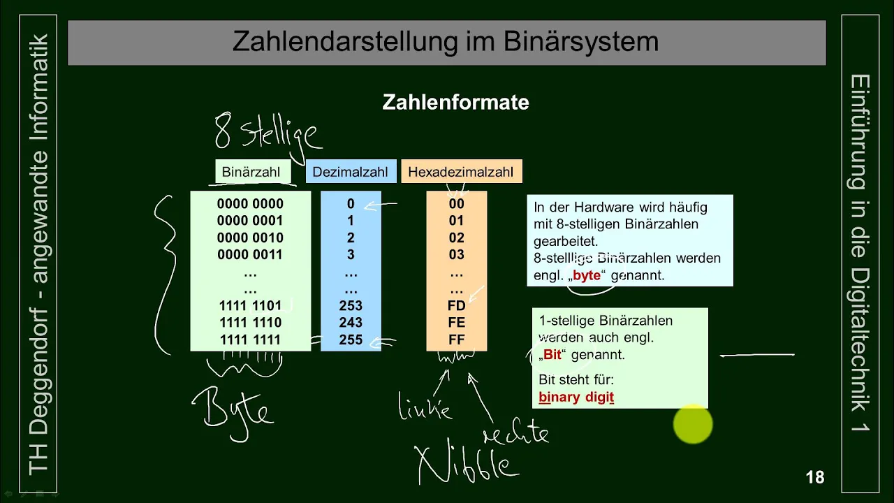
Fundamentals of binary and hexadecimal representation, including how bytes correspond to hardware registers.
Basic bitwise operations in C/C++ (AND, OR, NOT, and bit-shifting) to manipulate individual bits.
Writing and optimizing Interrupt Service Routines (ISRs) to execute time-critical tasks.
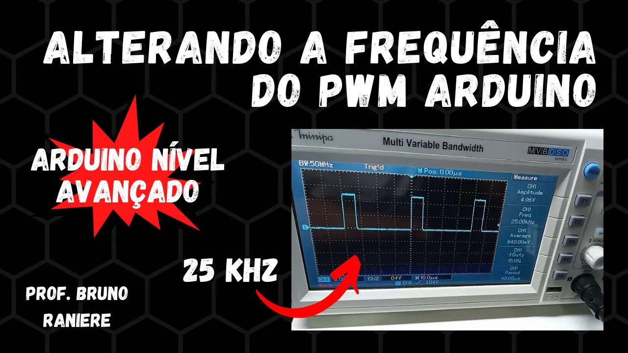
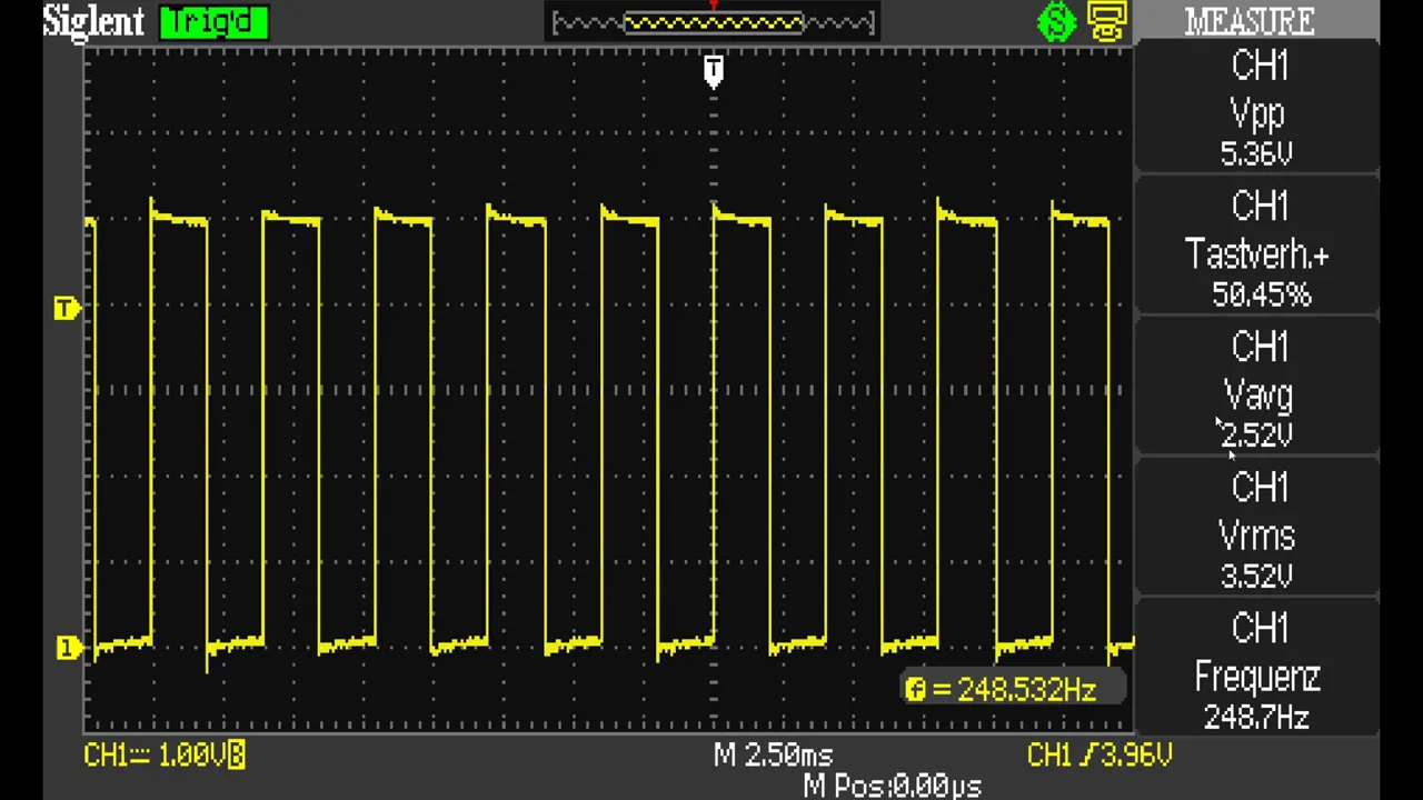
Configuring timer registers for Pulse Width Modulation (PWM) modes, such as Fast PWM and Phase Correct PWM.
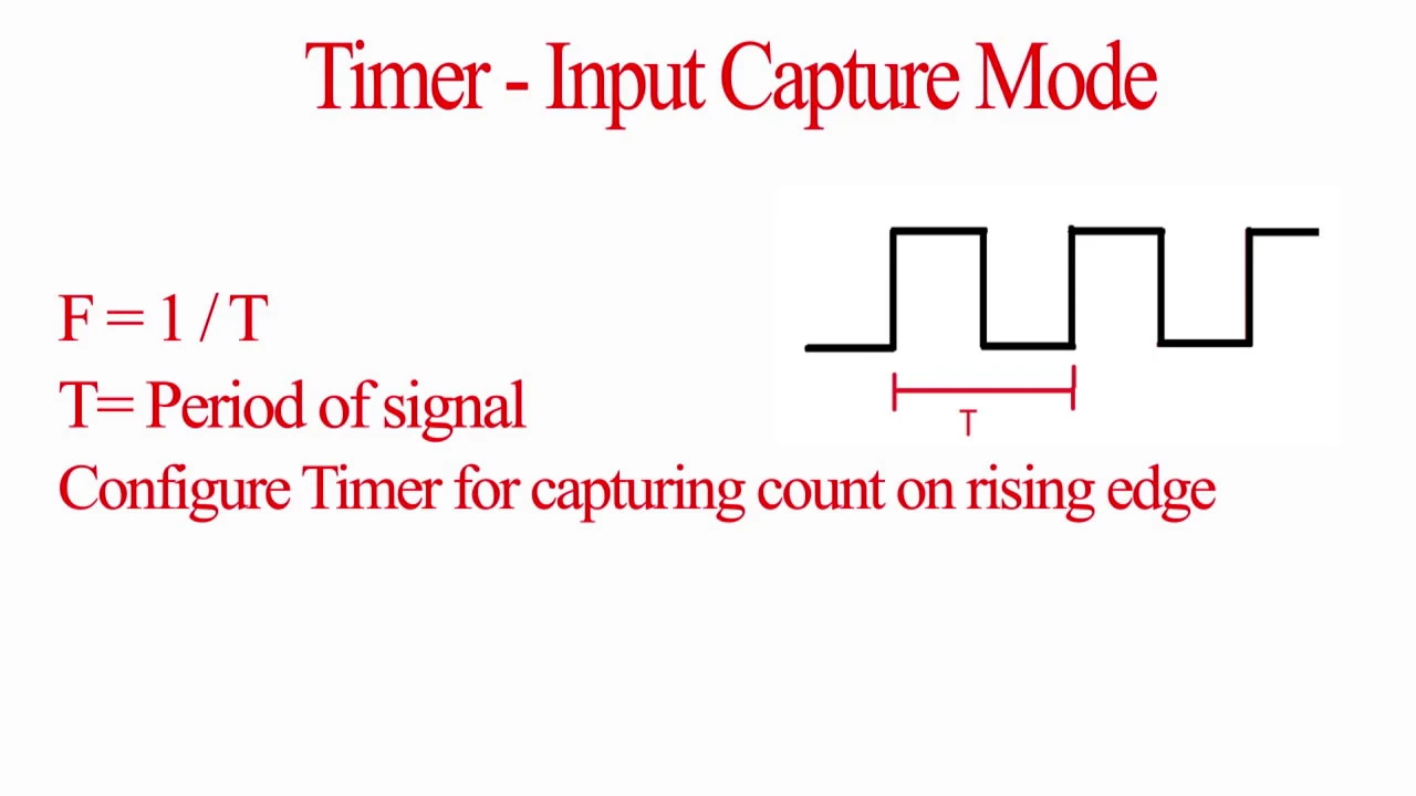
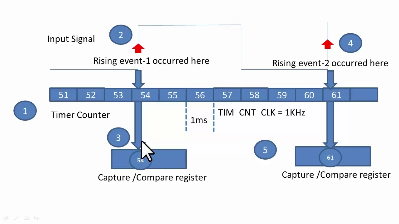
Utilizing Timer Input Capture to measure the frequency, period, and duty cycle of external input signals with high precision.
Transitioning from timer concepts to full bare-metal programming on the ATmega328P, including ADC and GPIO register manipulation.
Designing non-blocking, cooperative multitasking systems using hardware timers instead of the standard delay() function.
1.9K views29likes9:05Original Release: 2022-05-15
hello and welcome to another video on timer interrupts in this video we will be proceeding to talk about the registers so our goal in the series of videos is to understand the arduino timer interrupts and as i have said earlier there are three timers timer 0 1 and 2.
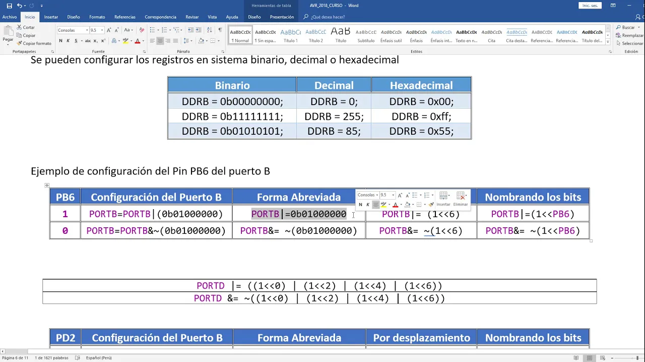
in this particular video we'll be talking about the related registers with these timers and their associated interrupt vectors so the first register that we shall be talking about is the timer control register this is basically a 16 bit register which exists in two parts tccr xa where x refers to the timer 0 1 or 2 and tccr xb so here i have circled 3 bits 2 bits in the control register a path a and one bit in the control register part b these are the w g m bits then there are three bits which i have underlined the cs001 and zero two bits these are a part of the tccr xb register these three bits help us to set the prescaler that i just spoke about so here are details from atmos datasheet on the microcontroller 80 328p so this says that to maintain a prescalar value of 8 you need to maintain the bets as 0 1 0 for 64 it needs to be 0 1 1 and so on so this is going to be our guidance for setting the bit values to get the desired value of prescaler that we want before we dive deeper into setting the bits for the desired value of the prescaler i will be talking a bit about bitwise operations the first bitwise operator is the bitwise or operator it operates as per this truth table as you can see here that if an existing value is 1 and i apply a 1 to it then the result remains 1.
so this table clearly indicates that if i apply a 1 to any value 0 or 1 then the value gets set as 1.
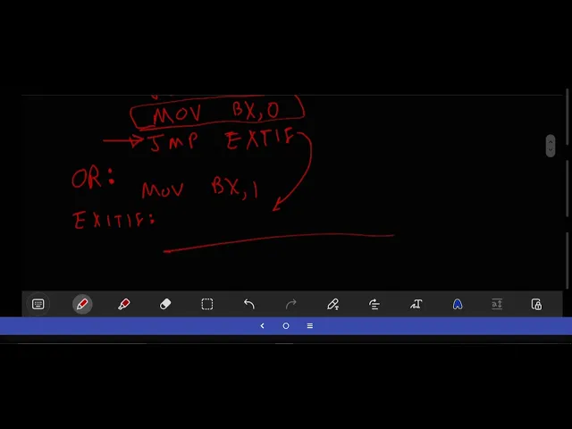
on the other hand if i apply a 0 through a bitwise or operator then the original value gets retained so if i want to set the fourth and the fifth bits to one then i would be doing a bitwise or operator as illustrated here then there's a bitwise and operator so the bitwise and operator if i apply a value of 0 then the bit gets clear if i apply a value of 1 then the bit remains unclear so this is kind of useful in clearing some of the bits so here i show an example in which the bits at fourth and fifth position get retained and the remaining bits get clear the third bitwise operator that's important in this context is the left shift operator its syntax is as shown here so if i do one left shift third bit then the third bit gets set as one and all the other values are zero similarly we have a right shift operator now we will see the use of these operators in setting the desired prescaler value so as per the table that i just showed you the prescaler value for 256 has to be 1 0 0 and this has to be set in the tcci 1d register so the first step is to do a bitwise or for the tccr 1b value with a left shift operator operated on cs12 so what i am doing is i am doing a bitwise or with the value bit 0 0 0 0 0 and cs 1 2 is third bit so that bit is set to 1 and the other 2 bits are 0.
so as i had just seen what a bitwise or does is that the zeros retain the bits and or with one always gives one so what this does is that all the bits in the tcc are 1b register retain as it is except for the third bit which gets set to 1 and that's what we want to do so the next value that i have to set is to set the cs 1 1 bit to 0.
in order to do this i first set the cs 1 1 bit to 1 then i invert the value using this tilde and then i do a bit wise and of the result with a tccr 1b value so basically i am doing a bitwise and with bit 1 1 1 1 1 1 0 1 that is there's a 0 at the cs 1 1 position and at all other positions we have a 1 and when we do bitwise and just as we had seen a little while later 1 retains the bits and a bitwise and with 0 gives us 0. so this basically clears the bit at cs11 sets it to 0 and leaves the rest unchanged similarly we do tccr 1b and equal to tilde 1 left shift operator cs10 so this again sets this bit the right most the left the right most bit to zero and so we by operating these three commands we are able to set the prescaler value to one zero zero or an effective value of 256.
the second thing that i would like to talk about is the waveform generation mode bits in this i shall be talking about the ctc mode which involves setting the wdf gm 02 to 0 wgm01 to 1 and wgm00 to 0.
so by setting this what happens is your timer on compare match mode is initiated what this means is that the timer can either go to a maximum value or overflow instead of doing that i set an intermediate value in the ocr a register and this intermediate value decides when the timer would get triggered for example if for timer 0 the intermediate value happens to be 100 then instead of going up to 255 timer 0 will trigger an interrupt when it hits the value of 100 and when this interrupt gets triggered because the ctc mode is enabled the timer gets reset to zero now there are two further registers the tcnt x register which is basically the actual timer or counter register this is the register which gets incremented as the timer runs in case of timer 0 and timer 2 it's a 8-bit register and for timer 1 it's a 16-bit register and then we have the ocr xa register which stores the value for the a value that is the output compare register a value so this is the threshold at which the interrupt would get triggered in case we don't want it to count up to the maximum value and so now we have three modes one mode is to let the timer run up to the [Music] overflow limit the other is to get it to trigger an interrupt when it reaches value a and one more option is to let it trigger an interrupt when it reaches value b and how do we select between these three modes for this we have the ti msk or timer counter interrupt master mask register and in this by setting the relevant bit we can decide which mode the timer would be operating on so this completes our discussion of all the registers to summarize the timers are associated with specific registers and in these registers there are specific bits which need to be set to certain values by setting it to these certain values we get the timer to behave in specific ways and these specific ways are enabling the timer itself getting the timer to trigger an interrupt when it reaches the maximum value triggering the timer when it reaches a certain specific value intermediate value and on reaching this intermediate value the timer can be configured either to restart set it back to 0 or it can be set to even continue the count thank you that's all for this video and i'll have one more video in which i will be covering a practical example with this
Up Next

30:32
Ultrasonic Transducers: Resonant Frequency Measurement and Horn Design
@imajeenyus42
229.9K views•2017-02-22

16:00
Using Low-Cost Transducers for Ultrasonic Sensing Applications
@TexasInstruments
72.8K views•2015-06-18

54:16
Polymer Environmental Degradation: Mechanisms & Stabilization
@iit
1.8K views•2012-07-10

33:39
How a Student's Question Saved a NYC Skyscraper from Collapse
@veritasium
22.8M views•2025-04-26
Related Study Plans & Knowledge Roadmaps
Structured learning paths in Engineering
engineering
Building Acoustic Levitators: Physics & Arduino
01The Physics of Sound and Standing Waves
02Piezoelectric Transducers and H-Bridge Drivers
03Arduino Programming: Generating 40 kHz Signals
+ 2 more learning modules
14h5 modules
Explore Roadmap
engineering
Building Peltier Cloud Chambers: Particle Tracks
01Cosmic Rays & Cloud Chamber Physics
02Thermoelectric Cooling (TEC) Fundamentals
03Custom Liquid-Cooling Loop Design
+ 2 more learning modules
18h5 modules
Explore Roadmap
engineering
Yagi-Uda Antennas: Modeling, Build & VNA Test
01Introduction to RF and Antenna Fundamentals
02Yagi-Uda Antenna Design Principles
03Antenna Modeling and Simulation in 4NEC2
+ 2 more learning modules
18h5 modules
Explore Roadmap
engineering
ECG Monitor Design: Op-Amps, Filters & Noise
01Electronics & Breadboard Basics
02Op-Amps and Instrumentation Amplifiers
03Bioelectricity and ECG Fundamentals
+ 2 more learning modules
18h5 modules
Explore Roadmap