








![Chargeur solaire fait maison [ de puissance ˃ 300 W ] , pour ma grosse batterie lithium !](https://i.ytimg.com/vi_webp/9Rz1I2fQnfQ/maxresdefault.webp)




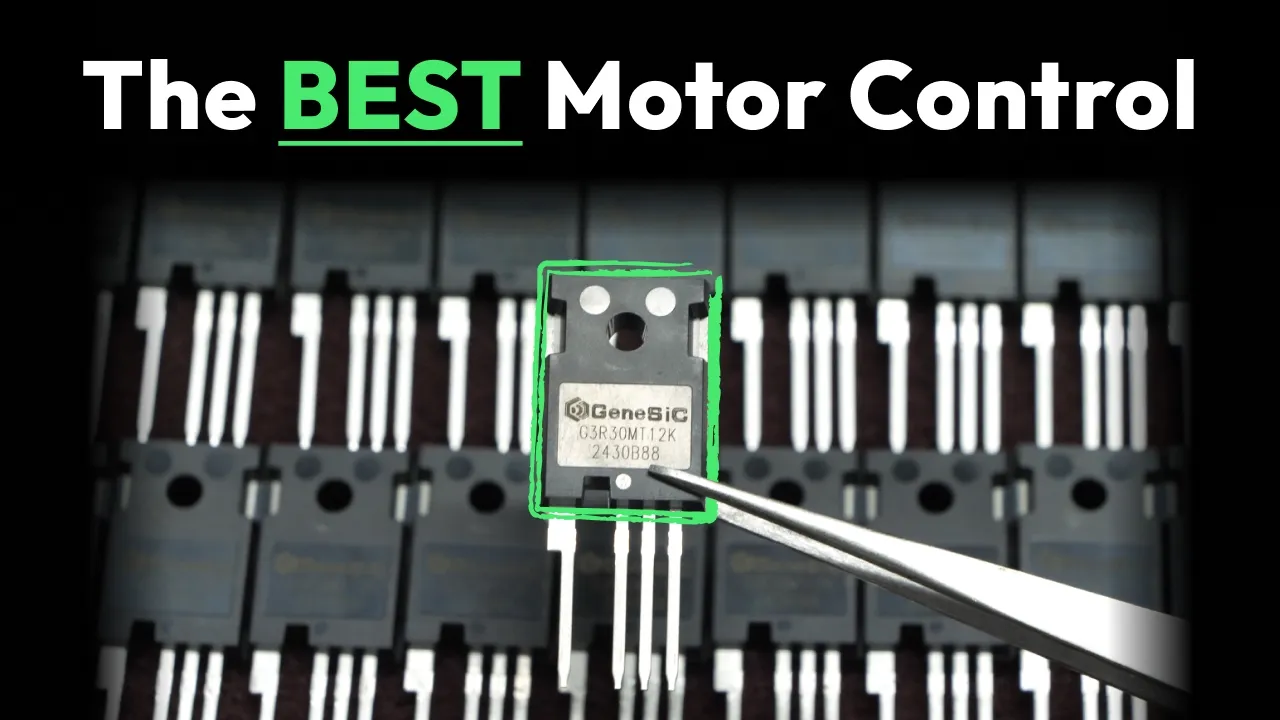








This tutorial explains how to generate complementary PWM pulses with dead time using the Arduino Nano IoT's TCC timer. The PWM frequency is calculated using the formula: F_PWM = F_CLK_TCC / (N × (TOP + 1)), where F_CLK_TCC is 48 MHz, N is the prescaler value, and TOP is the PR register value. For 33 kHz PWM with prescaler = 1, TOP = 1453. The dead time is inserted using the waveform extension control register, which prevents shoot-through in complementary PWM pairs (pins D2 and D6 are paired as WO0 and WO4). The timer must be disabled before modifying protected registers like the waveform extension control, and synchronization must be checked after enabling the timer.
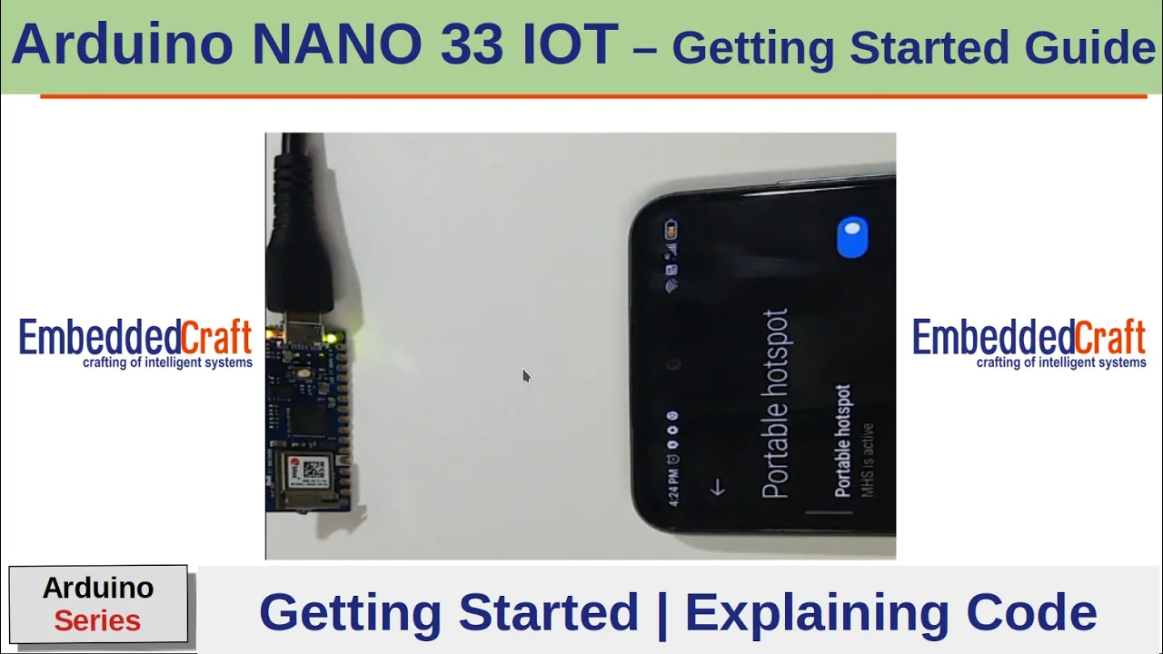
Arduino Nano 33 IoT Complementary PWM with Dead Time
Added:Basic Pulse Width Modulation (PWM) principles, including concepts like duty cycle, frequency, and resolution.
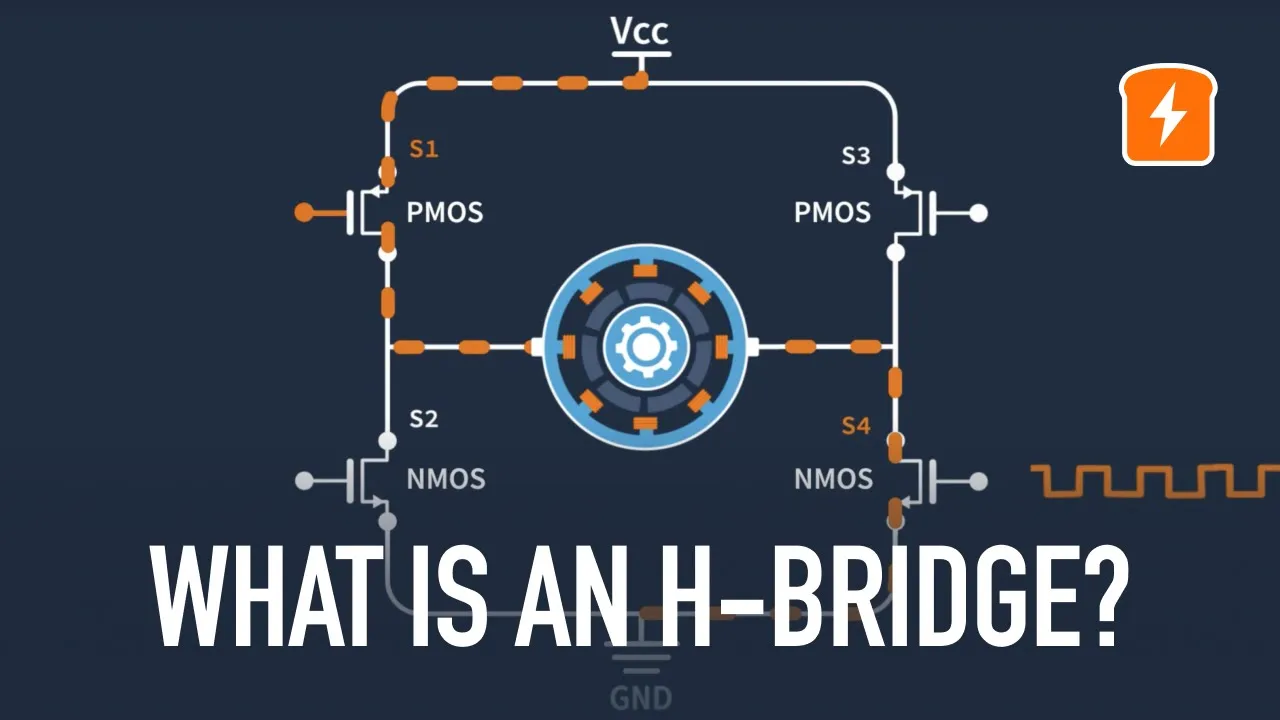
The fundamentals of H-bridge and half-bridge switching topologies, particularly the concept and dangers of shoot-through current.
Introduction to direct register programming in microcontrollers, moving beyond standard Arduino API functions like analogWrite().
Understanding the SAMD21 microcontroller architecture (specifically the Timer/Counter for Control applications - TCC peripheral) which powers the Arduino Nano 33 IoT.
Designing and driving synchronous buck/boost converters or DC-AC inverters using the generated complementary PWM outputs.
Implementing Field-Oriented Control (FOC) or sinusoidal commutation for Brushless DC (BLDC) motors.
Developing closed-loop control systems (such as PID loops) to dynamically adjust PWM parameters based on real-time feedback.
Exploring Direct Memory Access (DMA) to update timer registers automatically without CPU intervention for high-frequency control applications.
525 views8likes30:12Original Release: 2021-09-03
okay welcome back to the second part of this tutorial of the peterbeem pair with the dead time so uh in this sections we're going to study the timer setting so we need to learn how to set the register values for the pwm pulses so before we start i think we need to look at the data sheet of this timer counter for control applications so called tcc so we look at the block diagram basically they have a one counter which is either can counting upwards or counting downwards so if it is a counting upwards it will be compared with the top values if it is counting downwards it will compare with the bottom values so apart from that it also have a 4 compare or capture channels so called ccx so they have a cc0 cc one c2 cc3 so there's four compare channels for you to use so we'll learn how they're using the top and compare values to generate the pdf pulses and for after the comparison they will have a 8 output so called a waveform output from 0 up to 7. so this is the the output which is connected to our digital pin when you want to get the pwm this is the pin connected so if you look at the pin up yeah this is w o right w o zero so this is a cc0cc one okay so let's start with the functions descriptions okay so in this uh tcc they are able to generate seven types of waveform so the seven type of waveforms okay so listed at the below so the one we're going to use in this tutorial is the normal power swift modulations okay so we just use a normal power suit so or so called single sloop they'll only have single directions either counting upwards of downward for the dual slopes means though which is able to counting upwards and downwards together so what we need is just a normal pwm which is a single slope then the other two is the normal frequency and match frequency so normally this is used for the timer interrupts functions okay and we refer to these tables they have the mpwm or they call it a single slope pdf and the register they use is the pr register which is used as a top values okay this has to remember the p e r register is used as the top values okay then let's look into the descriptions on how this normal power simulation functions so if you look at the description basically this paragraph explains how the functions works and they tell you that the period of the pwm is a generate is controlled by the top values and the cci register is the one which control the duty cycle of the waveform so there's a two resistor which will control your pwm pulses which is the top values and we discussed before the top value in mpwm is using the per register so basically pr is referring the period and the ccx is the one which control the duty cycle okay so this is a two register into the monitor manipulate or change the value so that we get the period and the duty cycle we want our so-called frequency and duty cycle we want for our pwm pulses so the next part is explaining how it works we ran up counting and when down counting so basically that is same just one is counting upwards and one is counting downward the operations function is the same so we just refer to the upcounting and this figure also referring to the accounting okay so when is up counting the wo waveform output is set at a start so this is the waveform output means the the pin so the pin values so when they start counting upwards your waveform will start at the logic one so whenever they start counting your waveforms will go to logic one okay then uh it's set at the start or compare match between cow and top so whenever they reach the top they also will go to the set okay so either at the start or when they meet with the top values they also will go to the set so this is the same then they will clear go to zero means they will go to zero on compare match between cow and ccx so this is dotted line means the ccx value so means they match with the ccx value they'll go to zero right until they go to the top they go back up again okay then they meet so this is so there's this in this this is cycle they they make the ccx at the top so they will they will remain at that high level so nothing change so this is the complete pwm pulses this is this is the complete pwm process so from here you can know that basically the top is determining the period then the ccx depends what is the duty cycle of your pwm pulse when you're doing up counting okay so let's say i might have i want to have a higher d cycle i can just put my increase my ccx value to to higher values so they are mid at here then only they will go to zero at at this point so my waveform will become here so let's say i want to have a longer period so i just increase my top values so that it will go up higher again so let's say this is my new top okay so and this is my ccx so it will go down here then it will go there so compared to this one this one will be a longer period so this is how you change the period and the uh duty cycle by changing the value pr and also ccx okay so uh the period where we determine uh the the period determined by the step size so the clock cycle every clock they will count one values one one one by one until they reach the top so let's say i have a 10 10 count indeed the whole period there just times with the frequency of my clock then i will get the the the period one or whatever i just time one or f i will get the period of the whole pwm pulses let's say that my top value is a 10 right then i will get my period of my pwm pulses okay so the next part we need to know what how to get the frequency right so this is the formulas of for you to get the frequency of your pwm then the fgls fg clock underscore tcc is the one we use which is the 48 megahertz remember just now we are doing before this we're doing the clock we are setting it as this one so it's a 48 megahertz okay so 40 megahertz then divide by the n values times with the top plus one okay so it's a divided by the n value the end value is basically the prescaler the prescaler is a it can be one two four eight sixteen sixty four two five six and one zero two four which means you can change the you can resize the 48 megahertz maybe it's too high frequency you can lower it by giving it a 2n so means that divide by half it will have a 24 megahertz okay then divide by the top values plus one okay the top value is the one we define the pr register right so in here it's basically uh described how is the normal pivot functions this explains the functions how it works and this explains how you get the frequency so this is the two important [Music] information you should know about this single slope pwm generations so after we study all this thing then we will go to the register function register so how to set up our pwm by using the register so the first one is the control register a and if you uh look into the property this two thing you need to know this one is the enable protected so means this resistor cannot be modified or you cannot write any values into this resistor if the timer is enabled already so you must disable your timer in order for you to change the values in this control air resistor okay then there's another one is called right synchronize but they only refer to two bits which is the enable bit and also the software reset this two bit so means this this two bit when you want to change this to bit you must do something called a synchronized width for them to be set only you able to proceed so if you look at this look at the coding here you may find something like this one yeah enable right after i set i i do that enable so you can see before i set everything up i cannot do the enable i only do enable after i set everything up so initially they are disabled when we reset the microcontroller are in disable the timer so you you set all the pwm values or setting you want then you enable it so when i enable i need to wait for it to be sync so i need to check the sync busy bit of the enable there's one register called synchronization register synchronization resistor this register synchronization bc so they will check on this enable bit whether it's done or not right if you look at the description of the sync enable this bit is set when the synchronization of nlp between clock domain is start so it will be clear whenever it's complete right so that's why you need to check if it's still at one then you you won't go up from this while loops you will keep remaining here when it's zero then you go up from revoir zoo then you continue to the next coding so this is why you need to do the synchronization okay so you be noticed about this two things enable means if you enable the timer you cannot change the values in the controller you need to in the register you need to disable it only you can change and the second one is right synchronized means you after you write something you must wait until it's synchronized with the clock right for this two bit enable and software is set so the one you need is the enable bit so in this register the control a register the thing we need is just the enable and also the prescaler okay enable and the prescaler okay this is a prescaler laser enable so so the others we don't need because this is for the capture so we didn't use the capture mode then the other is a lock standby mode and resolution this is to change the resolutions but i think we donate for application we don't need to change the resolution to higher bit or lower bit okay so that this is the two thing you need to change so if you look at the prescaler so the prescaler is here right so you are able to change the clock frequency by changing the values in this bit 8 to bit 10 so if i put 0 at bit 8 to be 10 it will be a divided by b by 1 so if i put 1 at here it will deploy by 2 so for our code i put it at divide by one okay so if you want to change it to other uh prescaler you can just change it here okay this is defined in the arduino code already everyone should have this thing so you just change to two four whatever you want so in my code here i want 33 kilohertz i need a 33 kilohertz so i'm using 48 megahertz i just divide by one then i get my pe out it's a 1453 so that i get 33 kilohertz using the formula in here using the previous formula just now the one frequency function [Music] yeah using this formulas okay so i'm using this formula to get so my one is uh 48 megahertz then my n is a one my top value is one one how much one five four three is it one four five three plus one then it will be equals to megahertz it will be equal to uh 33 kilo hertz okay so if you don't know what is your p i should put p r here right then you just uh manipulate the equations bring it here and there then you'll get your pi equals one four five three in order for you to get to the tricky luts okay so this is the first part control then i'm using prescaler one if you want you can change the particular according to your application how much frequency you want okay then uh the limit of your setting you need to refer to the peer value the pr value is basically uh 18 bits only right start from bit 0 up to bit 17 okay if you want the higher one you need to deal with the resolutions if you want to higher bit you need to deal with the resolution already so that you can use the this this bottom part zero up to five okay but in our application i use 18 bit should be enough for me because my pr value is only one four five three it's within 18 bits i think it should be enough for 18 bits for most of the equations if you need then you need to do something in the resolution part okay you can refer to this resolution part yeah resolution part either that you know you can use uh what kind of a resolution you want okay then for control a the next one is enable one just just enable bit so if you want to start using it you just set it to one as the one we do it here okay and it will be so basically we've done this two thing this is to set the pr then this is to set the prescaler and this is to do the enable then this one is to set the waveform you want so this is in another register so let's look into the another register so waveform so let's go into the waveform yeah so in this part um there's quite a lot of other functions which we don't need in our normal pwm generations uh the swap we don't need the priority channels this is just to change the uh priority of uh our uh single slip and slow so whether you want to go up or down but we just use the default one so we don't need to chain it then the circular also don't need so the ram also donates so what we need to set in this waveform register is just the last three bits okay to let us use the normal pwm operations so we need to set it to two so that's why you set it to this one okay so this this is also inside the arduino library already you just type in this nokia it should be works basically meaning this bringing two into the this waveform register okay so that this is setting the waveform then if you look at it i think there's also need a synchronization if not mistaken so that's why uh yeah the whole register is right synchronized so that's why you see that we need to do the synchronization bit of this waveform register so after is a synchronized they only go to the next section i set the prescaler to 1 then i set the pr value so that i get 33 kilohertz so you can change the pr based on this formulas to get whatever frequency you want then this is the duty cycle i just put it to half like 50 okay so the ppr and also the cce also is the right synchronized so that's why they they need the uh this is the ccx see this one cc register also it's right synchronized so that's why you need to have the synchronized busy bit to check whether they have done or not okay so basically this is done all the settings for our device then the next part is the most important one is the dead time insertions and also which part we want to use for our applications okay so for the dead time setting we need to go to one part of the register so call the waveform extension control okay so this is the part where we insert that time so this is the dead time high side and the dead time low side so if we have a two a pair of pwm pulses one is a call as a high side what is called as a low side so they are inward complementary to each other so if you want both of them also have that time so you need to give the values into this this this portion so this portion is for high side this fortune is for low side so for me i just put them the same as i put them the same uh date time so uh so that they have the same dead time in the high side and the low side so it should be works fine to our applications uh and it is either the same how how's the dead time works is basically the same they are just uh using the clock counting so you just put the values in here then they will stop for how many clocks without generating any signals and the high side or low side so they will just remain at zero for that uh amount of clock you you define so let's say this is a two four six eight so it is eight bit total you can put two five five but i think two four five is too much already for for me i just put 50 start with 50 right so the high low side and the high side this two part is for the high side and low side so i just bring in 50 into the bit 16 and a bit 24 right bit 16 and a bit 24 right i just shift 50 into here so this whole thing will become 50 this will become 50 also right then the next part is the dead time enable okay so uh daytime able will explain to you how to do the dead time level but basically if you set it to one then that means they give you a dead time if you set it a zero they give you a no no that time so i want at that time then i need to check because i'm using pins d6 and d2 right so it's a 0w4 and wo 0 why i need to use the po0 and bo4 this is because basically they put them into a pair so i if you remember just now we go through we have a w0 up to w07 right so to okay then start with w04 w05 w06 and w07 so basically this this center is that expanding uh this diag basically pair in this form w o will pair with w the p o zero pair would be o four one will play five two i'll play six three or pair seven right if this is one then this is one divided by one eight divided by two so this is a this is five right it's one pair with the five right if it is zero then it is zero plus four so zero pair with four right this is basically a thing to use this way so means uh this is enabled for zero and four this is enabled for one and five this is enabled for two and six and this is enabled for three and seven right so that's why i only can use d2 and d6 because they are paired which are the zero and four one is high side one is a low sign right this is how they do it in this pwm waveform okay yeah this is to tell you which waveform output you want to use if let's say i want to use a one five then i need to check where is the pin one and five wo one so this is my w01 right w01 for tcc 0 then i need to check the 5 for wo w05 that is not not available in here right w05 i cannot see w05 so i cannot use one five right so what i can do is uh one five two six i can use two and six these two so these two pin i can use eight and nine i can use the pair also okay then the next one is a three seven yeah this one also can so one 1 5 okay i can using 0 4 1 1 5 cannot this one can then 2 6 can then 3 7 also also can this is for tcc 0 right then the next one the last one is um quite important the otm x setting yeah this is the output matrix so refer to this pin basically this is telling you which compare channel will put into your waveform output so if i set the values as a zero then my cc cc compare zero will go to my wo zero and this one cell one two three four five six and seven okay this is my waveform output zero up to seven so my cc zero will go to waveform zero waveform from two three four so that's why you can see four is the same one and five the same two and six is the same three and seven are the same so by using these values you are able to use four uh uh four different uh uh pairs of pwm pulses but in our arduino they don't have a one five so a maximum you can get is the three pairs on it right the zero two three five six and seven sorry four seconds seven five don't have one five panel right so this is the thing you can do by using uh mode zero okay but if let's say i only want to use a uh or using zero one i want to make them all the same i can just using mode two so by all my frequency i'll be the same but if i since i'm using the same compare right so if you are using different cc ccx so it's just a changes thing tcc one tcc two ccc3 something like that okay so that you can get the different tcc for your applications so if you look at it uh the this one is a date time we insert 50 then the next one is a one i shift eight chain to eight so you go to this one i shift it to eight so i just enable this one only right this is a bit eight i enable set zero and four so i set it to one right so this is uh what explained the code where i shoot with one then this is i shift two to the that one is a waveform matrix yeah i shift 2 which means i'm using this one i using all s o okay but if you don't change the same because uh one and four using the same cc or you put it at initial value zero so be this thing so because i'm just using uh outputs zero and four right so they're using cc0 am i using tcc 0 also so it would be the same if i didn't insert this line so basically this explained the whole thing right so uh hope this helped and uh the code of this thing is given in the in the slide uh in the in the link in the middle so we can just get the code and try to modify it coding to your application so for you to set the frequency you just need to set the prescaler either one two four six uh one two four eight sixteen uh something like that it refer to the data sheet you can change up to one zero two four you can divide then by using these formulas you can get your frequency one by changing the pr so remember pr if you didn't change the resolution is only 18 bit zero up to 17 right and this is the duty cycle so this cycle is based on this car values so if it's a one four five threes means it is full duty cycle if it's a half then 50 degree cycle so you just change this value to get that this is one then this thing is uh this thing is is the uh a deadband and also the uh enable it the deadband and which which which metrics you want to use okay so i hope i explained everything in this reviews and if you have any questions you feel free to comment below or you can send me an email to ask about coding okay so i think that's all for this one then one thing you need to notice is uh this resistor so if you want to change the value of this register you need to notice that this waveform extension control is actually enable protected so means after you enable your uh timer already you start the pdf accounting already then you you cannot modify the deadband already that time already what you need to do is you need to disable it so just set this to zero then you need to do the bgp also then only you can modify after you modify it then only you you need to enable it back again so this is basically how you do if you want to change the that time after enable it already okay remember this is quite important if you if you forget about this enable protected it may it may stop your micro tutorial from running if you put in the code okay so this is a thing you need to remember yeah things should be destroyed okay so this is the board i'm using to run the dead time pwm houses so i'm using a pin six and two so i connected these two to my scope signals and the ground pin i connected to my scope so i can start to run the code and you can see that in the screen of the yeah so this is this this is the waveform of the uh plm houses with the deadpan maybe i shave it down so you can see that there's actually a dead time in between the two signal right and the high side and the low side also they have the date time so basically this this this is the code which i'm using which are 50 values the number 50 i put in the dead time sections so you can try to increase whatever you want until you get the date time uh values you want so by adjusting the uh that time in the coding so basically this is a development board i'm using for my arduino nanobot basically these of iron another board but it's still applicable for the arduino iot okay so because most of the pin they are the same same locations just the voltage is different this is the nano is fiber this is a 3.3 volt so as you can see in this oscilloscope screen this is the waveform the pwm generated with the date time okay so i think this concludes the uh tutorial of our uh a pair of complementary pwm pulses with a dead time okay so thank you if you have any questions you can leave a comment below or you can even email me and ask the questions thank you
Up Next

91:37
Optimizing Home Theater Acoustics: Subwoofer Setup & Room Treatment
@Avrant
1K views•2021-01-22

12:54
Triumph of Orthodoxy Icon: Byzantine Art & History Explained
@BenCallan
2.1K views•2024-08-06

9:49
FastAPI vs Flask vs Django: Choosing the Right Python Web Framework
@TechWithTim
302.5K views•2024-05-26

1:42
Game of Thrones Opening Credits: A Cinematic Analysis
@gameofthrones
46.3M views•2011-04-18
Related Study Plans & Knowledge Roadmaps
Structured learning paths in General & Interdisciplinary Studies
general-studies
Elevator Engineering: History, Physics & Cities
01From Hoists to Safety Brakes: The Dawn of Vertical Lift
02Hydraulic vs. Traction: The Engineering Physics of Elevators
03Modern Speed, Safety, and Algorithms
+ 2 more learning modules
12h5 modules
Explore Roadmap
general-studies
Rubber: Material Science, History & Geopolitics
01Origins of Natural Rubber & Mesoamerican History
02The Chemistry of Natural Rubber & Vulcanization
03The Geopolitics of the Rubber Boom & Colonization
+ 2 more learning modules
12h5 modules
Explore Roadmap
general-studies
Containerization: Evolution, Logistics & Trade
01Ancient Trade & Bulk Cargo: Amphorae to Barrels
02The Industrial Revolution & Cardboard Packaging
03The Containerization Revolution: Malcom McLean
+ 2 more learning modules
12h5 modules
Explore Roadmap
general-studies
Textile Tech: Evolution, Labor & Global Impact
01Pre-Industrial Textiles: Handloom & Cottage Industry
02Mechanization: The Spinning Jenny to the Power Loom
03The Factory System & Global Labor Transformation
+ 2 more learning modules
10h5 modules
Explore Roadmap