






















Thermoelectric cooling systems use Peltier elements as heat pumps that transfer heat between two sides based on electrical current direction, with key design parameters including Qmax (maximum heat pumping capacity), Imax (maximum current), Vmax (maximum voltage), and DTmax (maximum temperature difference); successful design requires balancing heat pumping capacity against temperature difference, maintaining low ΔT for optimal Coefficient of Performance (COP), avoiding PWM-driven operation which reduces efficiency, and ensuring adequate heat sink capacity to prevent thermal runaway, typically operating at 30-70% of Imax depending on required temperature difference.
Thermoelectric Cooling Design Guide: TEC Controllers & Peltier Elements
Added:Fundamentals of thermodynamics, including heat transfer mechanisms (conduction, convection) and the concept of thermal resistance.
Basic semiconductor physics, particularly how p-n junctions function and the theory behind the Peltier and Seebeck effects.
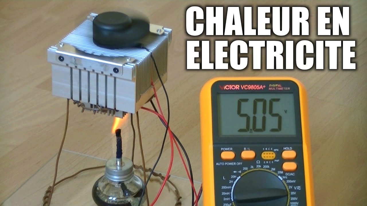
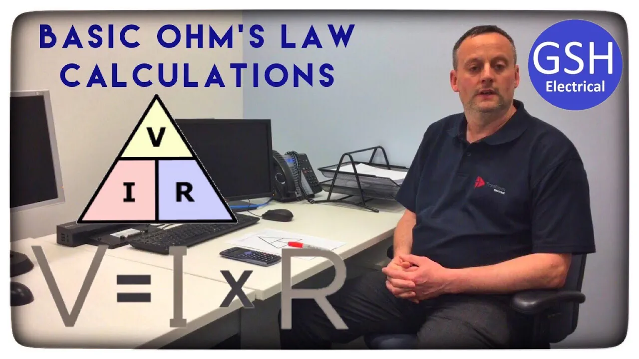
Core electrical engineering principles, such as Ohm's Law, Joule heating (I^2R losses), and basic DC power dissipation.
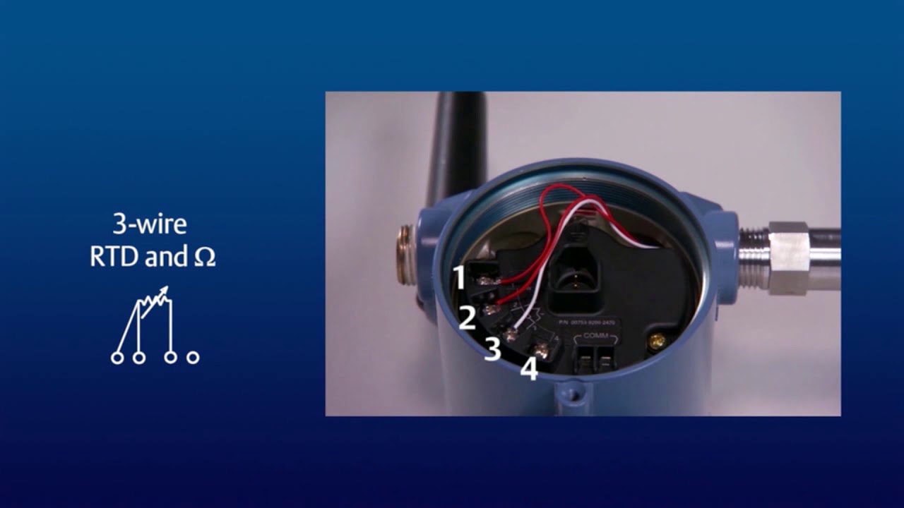
Basic feedback control concepts and common temperature sensing methods using thermistors, RTDs, or thermocouples.
Advanced thermal management system design, focusing on heat sink selection, fan sizing, and thermal interface materials (TIMs) for hot-side dissipation.
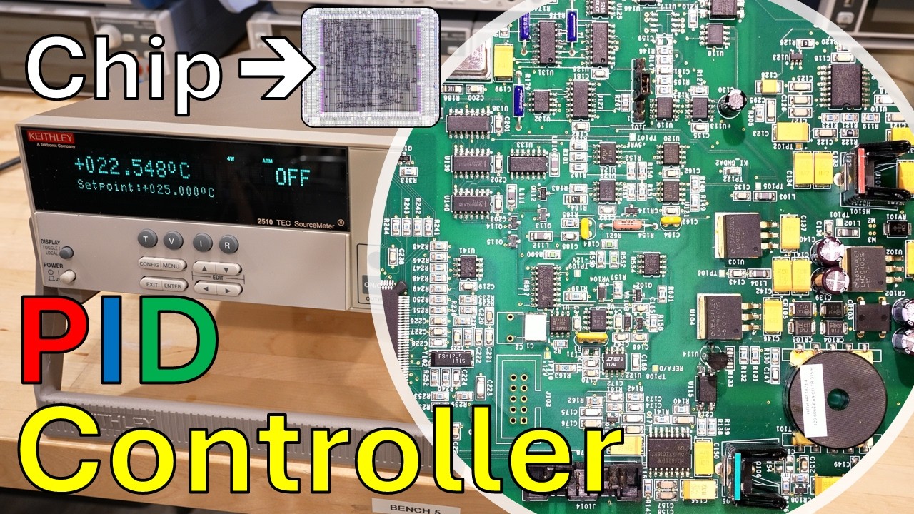
PID controller design and tuning specifically optimized for high-precision thermal loops.
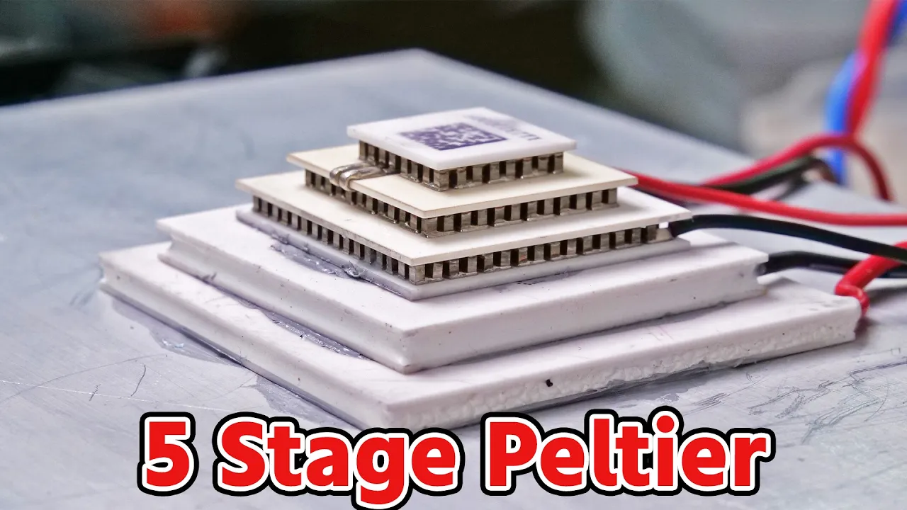
Design and implementation of multi-stage (cascaded) Peltier elements for cryogenic or high-temperature-differential applications.
Electrical drive architecture for TECs, including H-bridge circuit design and the comparison of PWM versus filtered DC current drive methods for thermal efficiency.
54.5K views303likes17:51Original Release: 2017-03-28
this video explains the basics of thermoelectric coolers and highlights important design parameters when outlining a thermoelectric cooling application the goal is to know the important parts of a cooling application and to avoid pitfalls in the design in thermoelectric cooling pelty elements are used to control the temperature of some object during this video and in our documents we just call it the object to be cooled PTY elements are heat pumps which transfer heat from one side to the other depending on the direction of the electrical current this allows Heating and Cooling the Tec controller regulates the current supplied to the pelty element according to the desired temperature of the object and the actual measured object temperature the object can be a sensor or a heat generating load like a laser diode which is placed on the so called cold side of the pelty element where the heat is absorbed on the so-called Hot Side a heat sink must be mounted to dissipate the Pumped heat depending on the temperature measurement the controller calculates the current that is necessary to drive the PTY element for cooling or heating to achieve a certain Target object temperature thermoelectric cooling is used in smaller systems where the solid state nature of the cooling systems outweigh the pure efficiency Tec modules also known as py elements exist in various forms sizes and performance categories PTY elements are characterized by four parameters qax IMAX Vmax and DT Max they can be found in every data sheet of a p element these are theoretical figures and they are used to describe the behavior of PTY elements a py element has a maximum heat pumping capacity Q max if the temperature difference between both sides is 0 Kelvin the current and voltage associated with qmax are IMAX and Vmax respectively DT Max is the maximum temperature difference across the PTY element when absolutely no heat is pumped nevertheless this maximum value is never reached in a thermoelectric application it is given by the manufacturer to characterize the performance of the pela module it's important to understand that the pel element will not produce these figures when just supplying enough current this graph describes the relationship between heat pump capacity on the Y AIS current on the xais for different Delta T's as heat is applied to the cold side the temperature difference is suppressed in a thermoelectric application there is always a trade-off between between heat pump capacity QC and temperature difference DT it is important to understand that only for relatively small delta T A significant amount of heat can be transferred multi-stage pel elements are used when higher temperature differences are needed if a high temperature difference is produced or a large amount of heat transferred more Jewel heating contributes to the total sum of heat to be dissipated the power of Jewel Heating is exponentially proportional to the current driving the pel element to visualize this we use a pel element with a qax of 63 watts and operated at 70% of IMX what corresponds to 8.4 amps the module heat pumping capacity is 15 watts at a temperature difference of 50 kelv we consult another diagram to see that if we operate a module at 70% of IMAX at the temperature difference of 50 kelv the heat sink must dissipate 75 watts in total five times the pumping capacity therefore cooling is the critical case of a thermoelectric application this is because heat must be removed from an object and together with the waste heat produced by the pelty element dissipated to the surrounding environment if a heat sink gets too hot the desired object temperature May no more be achieved in other words the temperature difference will get larger the controller will work against this by feeding more energy into the PTY element nevertheless this is known as thermal runaway and it is contraproductive since the heat sink will get even warmer with the additional waste heat of the cooler when you design thermoelectric cooling applications the coefficient of performance cop plays an important role the cop is defined as amount of heat pumped per unit electrical power supplied to the pelty element this is a plot showing the cop versus current relationship of a pelty element additionally the optimum curve is plotted in bright green showing the highest cop on the left side we see that the cop is maximum at the lowest temperature difference hence we get a high amount of heat pumped per unit electrical power therefore for an Optimum performance of the cooling system the temperature difference between the object and the heat sink must be kept as low as possible as we can see depending on delta T the corresponding cop maximum is at different current levels with higher delta T it moves to the right if we follow the curve to the right we find out that we must put a lot of electrical power into the system to get only a little heat pumped what what corresponds to a low Coop value we can also observe that higher currents are needed to produce higher temperature differences now we go back to the Heat versus current graph to understand the Dynamics of a system we can observe what happens if the ambient temperature changes and therefore the delta T or when the heat load is increased if you operate the P element with a current around 25% of aax it is possible to compens AR rise of delta T from point A to B by increasing the current the heat pump capacity stays unaffected the heat pump capacity can be increased as well without changing delta T if we move from a to c if the working point is around 60% of IMAX we need more current than in the previous example to compensate a rise of delta T Point D to E when the heat pump capacity should stay unaffected the heat pump capacity can still be increased without losing temperature difference if we move from D to F however if the pel element is operated near its maximum current a change in temperature can't be compensated by raising the current the transition from a lower to a higher temperature difference would result in a decrease of heat pump capacity as a first conclusion we see that we can add design margin by choosing a pelty element with greater than required heat pump capacity by designing a system with operating current well below aax of the pelty element or as a third option by oversizing the heat sink or adding a fan to it to keep the hot side temperature low by applying these measures a change in ambient temperature or active heat load does not lead to Thermal runaway as a rule of thump for temperature differences smaller than 20 K the cooling capacity of the pel element should be around five times the total cooling capacity necessary then we operate this cooling capacity with up to 30% of IMAX for temperature differences larger than 45 Kelvin the cooling capacity of a p element should be around 1.5 times the total cooling capacity necessary we operate then this installed cooling capacity with up to 70% of IMAX in this chapter I would like to highlight another measure to increase the systems efficiency the use of DC Curr instead of pvm output to drive the PTY element to visualize this we compared A Mir engineering DC current Tec controller against a pvm output Tec controller available on the market we made the following experiment as Target temperature for a one watt load as object to be cooled we chose in both cases 10° C in an ambient temperature of 24.5 de C both controllers fulfill the same need but in terms of efficiency the difference is quite striking in case of the pvm controller 56 Watts were used to keep the object temperature at 10° C this is more than six times more compared to the Meer engineering controller since more energy is put in the cooling system more waste heat must be dissipated this leads to a higher heating temperature 5° C more in this case and therefore to a higher temperature difference between the cold and the hot side the Final Consequence is that the performance of the PTY element is reduced in the case when pvm is used pvm current for py elements should be avoided and the controller with DC current used instead of less overall waste heat is generated the goal of this this part is to know the essential elements of a thermoelectric cooling system and to understand the important design factors which have an influence on the performance of the system for this purpose we disassemble a thermoelectric cooler and discuss the parts from which it's built from if the object to be cooled is relatively small and does not actively produce waste heat internally its temperature is prone to influences from the surrounding air in General objects and the cold side should be thermally shielded or insulated from the environment when possible this yields more stability of the object temperature and more performance of the cooling system since external influences are minimized sensor cooling applications are an example where this is important here we see a laser diet as an object to be cooled the object temperature sensor is fixed with a thermally conducting glue in the best case temperature sensors can be mounted by integration into the object to be cooled and not attached to it additionally to the object measurement input our Tec controllers also feature a heat sink temperature sensor input and an onboard fan controller as mentioned before a fan is another possibility to add design margin the heat sink sensor is used for optimal operation and precision of the thermoelectric cooling application with forced convection by using a fan heat dissipation to the environment is better since the termal resistance between the heat sink and air is reduced to be compatible the fans need to have a pvm control signal input and they should support the same voltage as the power supply for the Tec controller has now we can explore the mechanical construction by this assembling the Thermal electric cooler a convenient mounting option is to clamp the pelty element between the heat sink and a metal plate the metal plate for example made of copper or aluminum is used to achieve a homogeneous temperature distribution at the object's interface by using the metal plate the pelty element can be fixed and constant pressure is guaranteed avoid bending of the metal plate by choosing a plate sufficiently thck and by moderately tightening the screws however more thickness of the metal plate results in more thermal inertia make sure that enough pressure is applied onto the PTY element this also ensures good thermal conductivity the recommendation for the mounting pressure from the pelty element manufacturer should be followed reduce thermal resistivity and smooth out asperities by using thermally conductive Gap filler or grease another important point is to avoid heat transfer from the hot side to the cold side by mechanical elements this can to be seen in the analogy of an electrical short circuit while here for example a screw could be a thermal short circuit this can be avoided by using thermal insulation for screws a sealant between the metal block and the heat sink acts as a humidity protection for the PTY element the hot side with the heat sink should be on top of the system to minimize self heating of the system when a sufficiently large py element has been found we need to s select a suitable Tec controller all of our Tec controllers share some common features bipolar output current that allows Heating and Cooling without mechanical changes NTC PT 100 pt1000 temperature sensor input high temperature stability Standalone remote controlled and script controlled operation modes communication using open communication protocol API or l VI and fan controller we have learned that a pelty element should be powered with maximum 70% of its IMAX value or even lower percentages for small Delta T's with this in mind we look for a TC controller that matches the operating current for the application and not IMX this table shows our Tec controller product line from 1 ampere up to 32 amp after choosing the Tec controller the configuration of the Tec controller for the temperature measurement must be chosen two types of therm or sensors are compatible with our Tec controllers one type are the Platinum terms the temperature measurement range is betweenus 2 120° C and 200° C for NTC terms the Tec controller has an onboard reference resistor which defines the temperature range this resistor configuration can be defined upon ordering the table shows the possible configuration options and the corresponding temperature ranges this only defines the reference resistor and therefore the maximum measurable sensor resistance not the antc sensor type the sensor can for example be an NTC 10K what means that the resistance of the sensor equals 10 kilm at 25° C for the temperature sensor C setion the application and its temperature range dictates the kind of the sensor generally for temperatures fromus 20 up to 50° C NTC sensors can be used for other temperatures and high Precision measurements we suggest to use PT 100 sensors PT 100 or pt1000 sensors have the advantages that their characteristics meet International standards thus their interchangeability is good they have good temperature cycle Behavior as well as long-term stability the temperature range is large from very low temperatures to high temperatures NTC sensors have the advantage that they are cheaper than Platinum sensors and often they are smaller however the downside is that NTC sensors are not standardized and therefore interchangeability is limited another disadvantage is that the temperature range is not as high as with Platinum sensors the requirements for power supplies to drive the TC controllers are simple the voltage should be high enough and the supply just needs to have an output current high enough for the controller otherwise when the power supply is in its limitation the controller will shut down with an error the temperature measurement input of our TC controllers is highly sensitive to achieve a high measurement precision however this makes the input also prone to defects caused by external voltages therefore when integrating the cooling application into a system one must pay attention to a careful electrical design and wiring I would like to repeat some important points we learned in this video there is always a tradeoff between temperature difference and heat transfer capacity keep the temperature difference between the cold and hot side as low as possible and always add the margin to your termal electric application please refer to the product pages of the Tec controllers for more information don't hesitate to contact us for customized Solutions and detailed information about our product thanks for watching and enjoy the other videos
Up Next
21:03
ShangFang SF-101 Temperature Controller: Teardown & Circuit Analysis
@bigclivedotcom
69.1K views•2023-12-09

30:32
Ultrasonic Transducers: Resonant Frequency Measurement and Horn Design
@imajeenyus42
229.9K views•2017-02-22

54:16
Polymer Environmental Degradation: Mechanisms & Stabilization
@iit
1.8K views•2012-07-10

33:39
How a Student's Question Saved a NYC Skyscraper from Collapse
@veritasium
22.8M views•2025-04-26
Related Study Plans & Knowledge Roadmaps
Structured learning paths in Engineering
engineering
Building Acoustic Levitators: Physics & Arduino
01The Physics of Sound and Standing Waves
02Piezoelectric Transducers and H-Bridge Drivers
03Arduino Programming: Generating 40 kHz Signals
+ 2 more learning modules
14h5 modules
Explore Roadmap
engineering
Building Peltier Cloud Chambers: Particle Tracks
01Cosmic Rays & Cloud Chamber Physics
02Thermoelectric Cooling (TEC) Fundamentals
03Custom Liquid-Cooling Loop Design
+ 2 more learning modules
18h5 modules
Explore Roadmap
engineering
Yagi-Uda Antennas: Modeling, Build & VNA Test
01Introduction to RF and Antenna Fundamentals
02Yagi-Uda Antenna Design Principles
03Antenna Modeling and Simulation in 4NEC2
+ 2 more learning modules
18h5 modules
Explore Roadmap
engineering
ECG Monitor Design: Op-Amps, Filters & Noise
01Electronics & Breadboard Basics
02Op-Amps and Instrumentation Amplifiers
03Bioelectricity and ECG Fundamentals
+ 2 more learning modules
18h5 modules
Explore Roadmap