





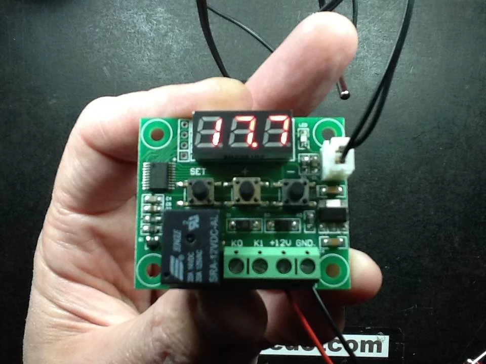











A ShangFang temperature controller uses a traditional potted 2VA transformer for reliable power conversion, an external high-current relay (rated up to 30A) for load switching, and a microcontroller-based design with filtering on thermistor inputs. The controller features programmable settings including temperature setpoint range limits (E1-E2), hysteresis (E3) to prevent rapid cycling, delay start (E4) for motor protection, and thermistor calibration (E5). The PCB supports up to three external relays and two thermistors, with a fourth button provision for additional functionality. This modular design allows easy component replacement and makes the unit suitable for both heating and refrigeration applications.
ShangFang SF-101 Temperature Controller: Teardown & Circuit Analysis
Added:Understanding of basic electronic components (resistors, capacitors, diodes, and transistors) and schematic diagram symbols.
Fundamentals of electromagnetic relays, including coil activation, contact switching, and galvanic isolation.
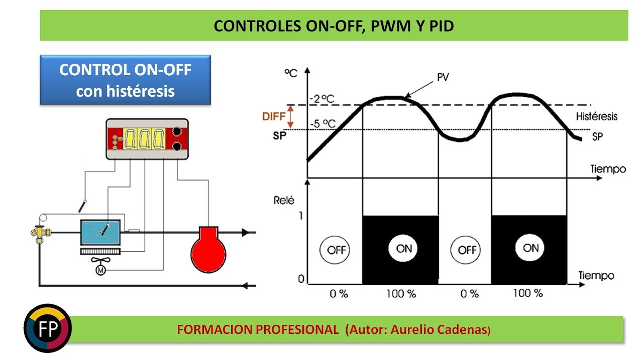
Basic concepts of temperature control systems, specifically on-off (bang-bang) control and hysteresis.
Knowledge of AC-to-DC power conversion principles, including linear, switching, or capacitive dropper power supplies.
Design and implementation of PID (Proportional-Integral-Derivative) control loops for precise thermal regulation.
Advanced power electronics switching devices, such as Solid-State Relays (SSRs), TRIACs, and optocouplers.
Practical PCB reverse-engineering techniques, including trace tracking, component desoldering, and schematic generation software.
Microcontroller-based embedded system design for sensor interfacing (RTDs, thermocouples) and display multiplexing.
69.1K views3.7Klikes21:03Original Release: 2023-12-09
in previous videos I have looked at various versions of these SDC 1000 generic clone type temperature controllers and ones like this one 100 to 220 volt they usually don't have great power supplies inside and they don't have good electrical separation from things like the low voltage uh temperature probe however I decided to go on and get a decent one that you might find in commercial equipment and again it is manufactured in China everything is but this one is definitely A Cut Above I got this from eBay it was a lot cheaper than the standard ones because I get the feeling the person that was selling it didn't know how to use it and also thought it was for refrigeration it's not this one is for heating uh the instructions that come with it are in chines but I did find a fairly sensible data sheet and can explain the functions of it so first thing that is notable it comes the traditional Transformer this is a potted 2vt amp Transformer let's Zoom down a little bit rated for 12 Vols AC put at 160 milliamp that is separate from the unit itself and that means that if the power supply burns out you can just change the power supply although having said that this is a traditional chunky heavy uh magnetic Transformer so it's very unlikely to fail next we have the unit itself which takes that AC Supply in and it has three sets of cables coming at the back it's got the temperature sensor with a nice rugged rubbery cable uh and it's got the power in and the uh two sped connectors the two sped connectors are for an external relay and unlike the little cheapy ones that have suspicious tiny relay in them with a very very debatable rating on them this is using a hongan hold on let me just get the let me just zoom in in this with my magnifying glass it's it's a song song Schwan relay and if this is real this is a fairly good quality relay and you basically the speed connectors and they go onto the two small connectors and then you switch your load externally to the unit just with these two terminals here and it is rated theoretically up to 30 amp it's rated for switching compressors and it's rated for switching heaters directly and again if this fails you just pull off these connectors you screw another one on and that you you don't have to change the whole unit so let me hook this up so I have somewhere here a little means Supply cable and I shall find a suitable screwdriver here and it's notable I wonder if there there's a circuit board in here because the terminals here are typical circuit board type terminals but they're not always used that way sometimes they're just basically poked through the casing and then soldered in the back of but you don't want to overtighten these because if they are in a circuit board overtighten them like really monkey style uh can actually physically snap the sodar connections inside so let's get the two leads it's AC so they're not polarized they can go in either way around so I shall stick them in and the other one and we're ready to power up I shall put the Spade terminals back on to this relay so you can hear it clicking I could just unravel this no I won't unravel it it's fine it's probably better not unraveled good generous length of cable because again it's designed for commercial use and uh having too much is better than having too little right let's plug this in and see what happens so when you plug it in I'll turn it the right way out for this it does a we display test initially then the relay Clicks in because the temperature is current ly set to a sensible 20° C indoor temperature and it's brought the relay in uh keep in mind this is all Opera low voltage it's brought the relay in uh because it's calling for heat because it is a heater unit the user can press this button to front and uh normally it displays a temperature in the room 14° C at the moment which is quite High actual temperature 10° it's because I've obviously handled this recently uh but if you press this button the user can then say right I don't want it so hot so I'll cut it down to about 15° C and then press set and because it's reached the temperature it will cut out and if it the temperature drops again it will turn back on again there is a limit to the user's interaction here because if the person who sets this up presses and holds a button in this for 6 seconds then it gives you option one and you can click through uh several options here but option well the one that will interest the Americans is C1 which uh if you then press it lets you choose degrees Celsius or degre Fahrenheit I'm going to keep it Celsius uh set E1 sets the lowest temperature you can set it to it's currently set for zero but you could say I don't want them to turn if this was being used as a room thermostat you could say I want it set for a minimum temperature they can Center to 5° so that if it gets really cold and the building is not occupied it brings the heating on to avoid Frost next option E2 this is the temperature that they can set up to so I'll I'll make a note of all these things down in the description down below so you could say I don't want uh the typical office worker who feels the code quite easily they will if you set it if you allow it to go up too high they'll just basically run it up they'll use it as an accelerator and they'll set it to 100° C so the heater just runs all the time so let's set a a maximum cap at 25° C O I've just uh exited out that I shall go back in then it shows its pedigree here because uh E1 E2 that's the upper and lower temperature E3 is the temperature hysteresis which uh is the difference in the temperature it allows a SL margin so it doesn't oscillate on and off around the temperature you've set so you can set a couple of degrees that it Lally it won't come back on until it's dropped a couple of degrees below that and then it will kick back and it won't do it as soon as it goes one degree below that and because I've backed out that I'm going to have to go back in again I'm just looking at my notes here so the next setting is E4 this is set to zero but you can actually set it up to 3 4 5 6 7 8 9 10 if you want and what this is It's because this is a universal device it sets the compressor delay or supposing you had a heating system with a great big motor and you didn't want it to cycle too much um then you could uh basically it sets a delay that minimi that minimize the time well that sets a minimum time before equipment coming on and off uh in the case of compressors that if you have a refrigeration compressor and this is probably where they've got that setting because this is a universal module that just has certain parameters set um if you have a refrigeration compressor you don't want to cycle on and off because if you turn a compressor off and then start it up fairly quickly afterwards it may stall against the pressure um and also you want to limit the number of cycles of high param motters so the next setting is calibration I believe and this is one two three five yes this is set to zero but you can actually go a minus temperature or a plus temperature and what that means is if you put the probe in and say for instance it's displaying uh a temperature of um 20° in the room but you use a calibrated ther thermometer next to and it shows it's actually 22 you can actually nudge the value using that so the display reads correctly it just basically allows you to calibrate in on site now I did discover another menu in this I haven't explored the other menu it's not documented this is not a good thing uh but if you press and hold this when it's in one of the other things it displayed cop last time is it going to do it again ooh I don't know what that means ooh shouldn't really click things when you're pressing cop I don't know what that is yeah I don't know what that is cop I'm not going to do anything with that because that's uh I don't know have you ever been working a piece of industrial equipment and you press a button and it displays a random menu item you don't know what it is and you try and back out and but it's too late you've changed something and then the machine stops working that's what that's all about so those are the main settings uh I think that is it that is all the settings you've got E1 2 3 4 and 5 and the uh Centigrade or Fahrenheit or Celsius and Fahrenheit okay right let's try and open this up and this is going to be made tricky because I can feel here and because it's designed for industrial applications they've sealed the back as well to stop bugs and moisture getting in h and that is going to make things just that little bit harder when you actually install this and you feed it through the panel these little things just slide on and they click up and you just can click them in multiple positions to actually just lock it into position the panel and it's got this sort of spring for holding it in yeah there're silicon all over this this isn't great I may be able to drizzle isopropyl alcohol over over the wires and free them up I shall try that but it may actually limit what I can actually get out here the isopropyl alcohol dissolves the uh it stops the hot milk glue adhering it's not necessarily going to help much the cables I'll just shake all that off now I'll disconnect the wires while it's uh permeating in I like the fact they've supplied the separate Transformer and the separate really it makes it so much more serviceable I shall shake off the residual isopropanol and poke around here and see is this basically going to free these wires now yes it is this is good we may actually be getting in here I may have to do this again once I've opened it just to uh free it up a bit more it's not going to help the figure8 cables because the glue will have seeped down between uh those connections but we'll see what happens now theoretically I should get a sharp knife and just slit this label cuz it is one of the easiest ways to get through labels I've just slit it way offline there I was hoping to go into the little Groove and have it guide across now I can see loads of silicon under here and it's making squishy silicon Rippy noises but that's not guant guaranteed to get us access but it's a start if it takes ages I shall pause momentarily while I gouge into this oh this is this is looking promising this is looking very promising I think I may actually have to slide this up under here though what I'm expecting is a very simple rectifier uh and a smoothing capacitor operating at 50 60 HZ so no real stress on them oh this is us we are more or less in the circuit board is latched into the front there let's see I can feed these through I don't want to snap wires off tell you what H now I'm in this far I'll pop the circuit board out see if I can just pop this out here there there's display complet with this protective film completely this buttons in a spare button position oh that's for options is what it's for the ther cable is the easiest to push in because it is round the other cables less so if it comes to oh no no they're coming off they're coming off or should I say they're coming into it I'll try and stay in shot here because I am zoomed in pull this one this way and then pull it that way this is looking very very promising right I shall get rid of more of the hot milk glue I'm seeing the well I'm seeing part of a brid direct far here where's the rest of brid direct far oh there's the brid direct far these oh I know what this is for this is other outputs so this is an output with a protection D for the again cross the call there's the transistor that switches it right well you know what we do now I shall take a picture of this from a couple of angles and we shall reverse engineer and see what makes this special one moment please reverse engineering is complete let's explore this is going to look a bit cluttered I'll Zoom down this and the reason it's looking a bit cluttered is because this is the bottom circuit board and that's the top circuit board so you can see the capacitor here sticking up there and the voltage regulator here sticking up there and so on I couldn't easily separate them because there are 30 uh connections with a circuit board slotted through another one and the risk of uh damaging it uh was just too high because it is a double-sided board so I decided not to do that and took the picture of it in position that's why it looks just a little tiny bit cluttered now this is first and foremost designed as a universal unit it's clearly designed from the fact there's three outputs here uh it's designed to switch three relays for uh ref Refrigeration equipment and I could imagine that this would be a standard controller used in cases and colds because it has the compressor output here it's got the defrost heater output here and it's got the fan here and normally in say for instance a Cod Room or a refrigerated case in a supermarket you'd have say the compressor uh running to bring the temperature down on the evaporator but every sof will switch into defrost and it turns the compressor off it turns the fans off and it turns the defrost heater on now sometimes it's just drip natural drip down sometimes it's hot gas but in this case it's probably a heater it be designed for and it would basically defrost the evaporator to stop it icing up and then it would turn the heater off wait for a time delay then turn the fan on and the compressor on again so that's why it's got those outputs it also has the facility for a beeper up here for alarm situations so let's go over this circuitry the AC comes in here the 12 Vols AC and it goes through this bridge right far it then forms a rectified and smooth 12vt rail which actually waivers between 14 to 17 volts depending on the uh load and that gets Smooth by this capacitor then there's this voltage regulator and then another capacitor with a filtering capacitor which I didn't actually color in but it's just in parallel with this one and it provides the supply rails to the rest the circuitry the microcontroller is tucked down under here and it drives the display and the buttons with multiplexing the thermister inputs uh it's got the facility for two here but it's actually got an extra one up here not I'm guessing there's probably other boards that go onto the same display board because it does have the option for a third thermister that isn't implemented down here but what is implemented down here is the uh unregulated 12vt output the ground and uh a data line connected probably to microcontroller couldn't really trace it back because the component in the way but there is a resistor between that and i' guess it's just data more or less from the microcontroller uh to control the remote uh display and button interface um after that anything else worth mentioning here there is a programming Port um right schematic and the schematic is abbreviated just because it would be very cluttered otherwise here is the schematic I zoom down just a tiny bit more watch me over zooom no that's perfect that's ideal here's the 12v C coming in from the chunky Transformer I I just tapped the Transformer offshot there there's a 470 micard capacitor quite a high value but that's only because unlike switch mode power supplies you're used to seeing low value capacitors because the AC is at very high frequency in this case it's at 50 or 60 Herz so this only has to deal with one well this has to do with 100 100 12 Herz Ripple and it just means the capacitor is bigger and will last longer it goes through a 5vt regulator 7805 and then there's another capacitor for smoothing 220 microf 25 volt and that provides the 5vt rail for the microcontroller and other circuitry the therm inputs have mega filtering on them there's the external 10K NTC thermister and there is a 100 Nano capacitor across it that that's matched to create a potential divider with another 10K resistor to the Z volt ra and it also has a filter capacitor across it so a lot of filtering to make sure the microcontroller sees a nice stable input even if there's long cable runs because uh when you've got a uh thermister cable running near Main's cables which is preferably it be rooted away from them it can pick up noise and this just provides filtering and gives an average value that is then decoupled from the micr controller with a 22k resistor the microcontroller then drives the display via a series of resistors standard Multiplex display and also the buttons are all Multiplex too it then has effectively four transistor outputs uh three for relays with a snubber diode across them and the reason for the snubber DI is when you turn a really off the magnetic field collapses but because it's effectively collapsing into an open load the voltage Spike can be quite high and it can potentially damage the transistors so what they do is they put the diard across and when it collapses it just basically diverts it through the diode and shunts that collapsing field um and it's a standard npn style y1 transistor the three are used for the relays and one is used for the Sounder and it's just that's more or less it it is well abbreviated there was no point drawing all this it would have taken a lot of tracing around and been fairly pointless but there are other features on the board for other things um it's just a universal board it's quite nice it makes sense to design stuff like that so you can have multiple applications I shall bring this circuit board back in again noting that they have got most of the component values marked including uh the decoupling capacitors for the thermister input 104 that means 1 Z and 4 Z is 100,000 picofarad which is a base unit of measurement there and then that is of course 100 nard and it's just it's an absolutely standard value throughout 47 ohm for most of the multip flexing resistors for the LEDs and the switches and then a 5.1k uh resistor to the uh buttons just uh presumably to prevent the uh Multiplex lines being short circuited it's very straightforward uh and just nice because it does have all these components that just make it reliable they and they're all serviceable they're all external to the unit you've got that chunky uh traditional long lasting Transformer you've got the easily swapable chunky relay that is a good brand and you've got the uh power supply which is zero uh sort of high frequency components as such is literally just a low frequency power supply which means this unit is clearly designed to last it's a it's reliable looking whether this is a clone or not I don't know www.fb.com but there we have have it this is model sf-101 sh general purpose well in this case a heat temperature controller very versatile looks very good
Up Next

35:54
Solo GIS Consulting with FOSS4G: Workflows and Tools
@foss4gna58
624 views•2016-06-01

30:32
Ultrasonic Transducers: Resonant Frequency Measurement and Horn Design
@imajeenyus42
229.9K views•2017-02-22

54:16
Polymer Environmental Degradation: Mechanisms & Stabilization
@iit
1.8K views•2012-07-10

33:39
How a Student's Question Saved a NYC Skyscraper from Collapse
@veritasium
22.8M views•2025-04-26
Related Study Plans & Knowledge Roadmaps
Structured learning paths in Engineering
engineering
Building Acoustic Levitators: Physics & Arduino
01The Physics of Sound and Standing Waves
02Piezoelectric Transducers and H-Bridge Drivers
03Arduino Programming: Generating 40 kHz Signals
+ 2 more learning modules
14h5 modules
Explore Roadmap
engineering
Building Peltier Cloud Chambers: Particle Tracks
01Cosmic Rays & Cloud Chamber Physics
02Thermoelectric Cooling (TEC) Fundamentals
03Custom Liquid-Cooling Loop Design
+ 2 more learning modules
18h5 modules
Explore Roadmap
engineering
Yagi-Uda Antennas: Modeling, Build & VNA Test
01Introduction to RF and Antenna Fundamentals
02Yagi-Uda Antenna Design Principles
03Antenna Modeling and Simulation in 4NEC2
+ 2 more learning modules
18h5 modules
Explore Roadmap
engineering
ECG Monitor Design: Op-Amps, Filters & Noise
01Electronics & Breadboard Basics
02Op-Amps and Instrumentation Amplifiers
03Bioelectricity and ECG Fundamentals
+ 2 more learning modules
18h5 modules
Explore Roadmap