A closed-loop stepper motor can be created by attaching an optical rotary encoder to a standard stepper motor's shaft, enabling position feedback for precise control; this mechanical modification involves extending the motor shaft, designing a custom mounting plate with CNC machining, and preparing mounting holes and threads to secure both the motor and encoder together.
Converting a Stepper Motor to Closed-Loop with Encoder
Added:Deep Dive
Fundamental operating principles of standard stepper motors, including step angles, phases, and how magnetic coils are energized.

SPECIAL MOTORS TYPES WORKING CHARECTERSTICS APPLICATION
318
A stepper motor consists of a permanent magnet rotor and electromagnetic windings on the stator. When current flows through a winding, magnetic flux develops according to the right-hand rule. The rotor moves 90 degrees clockwise when the upper electromagnet is deactivated and the right electromagnet is activated, aligning with the active magnet. The step angle equals 360 divided by (n × p), where n is poles per face and p is number of phases. For a three-phase motor with four rotor teeth, step angle is 30 degrees (360 ÷ 12 = 30). The rotor completes 360 degrees in four steps, with each step creating magnetic locking between opposite poles.
Click to watch →
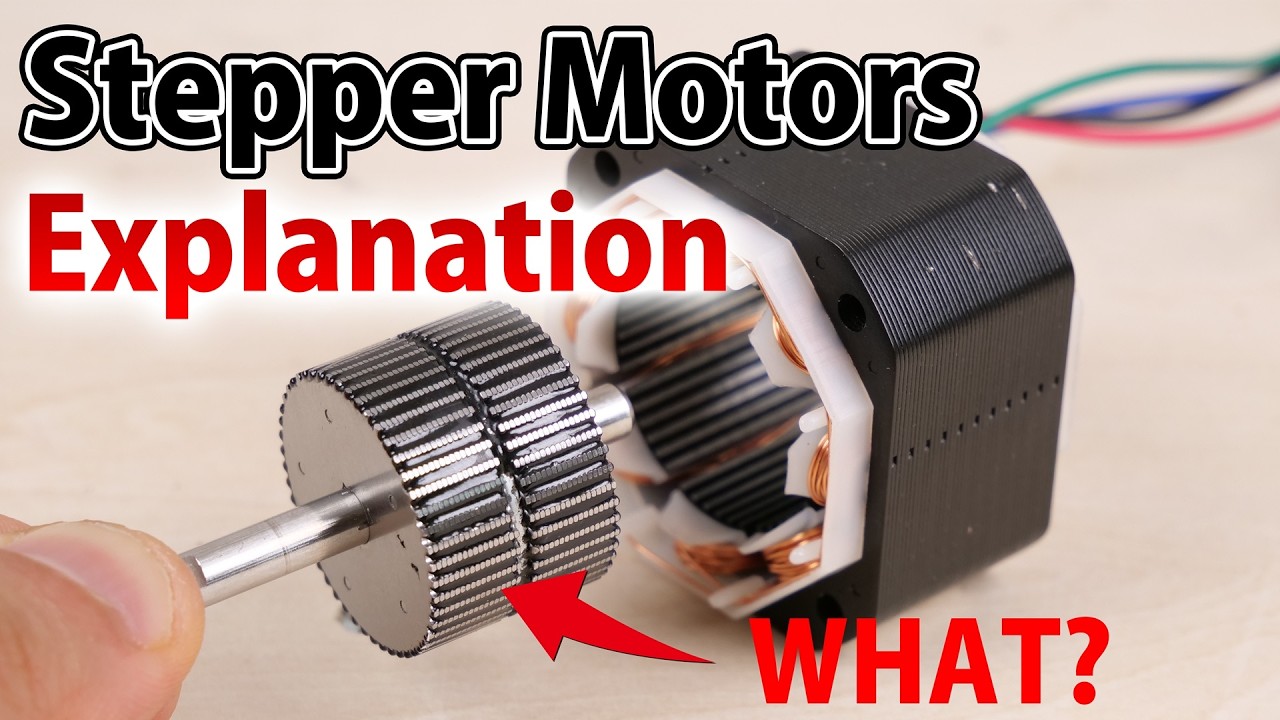
Stepper Motor, Operating Principle and Structure Explained
81.3K
A stepper motor consists of a rotor with a magnet covered by magnetized rotor cups and a stator with iron cores and coils; it operates by passing current through specific stator coils to create electromagnetic attraction that rotates the rotor in discrete steps, with the step angle determined by the motor's physical structure rather than requiring feedback sensors, making it suitable for open-loop control applications.
Click to watch →
Tipos De Motores Eléctricos - DC/AC | Síncrono, Sin Escobillas, Stepper, Servo
178.7K
Stepper motors are brushless DC motors designed for precise positioning. They have stator and rotor teeth arranged in specific patterns, with two main coils (A and B) controlling movement. Each coil energization moves the rotor by a fixed angle (step angle). For a 17HS motor, 200 steps per rotation means 1.8 degrees per step. Smoother rotation is achieved by energizing adjacent coils simultaneously, halving the step angle. Microstepping further reduces step size. Controllers like A4988 or TMS2209 manage coil sequencing.
Click to watch →

#54 Electrical Machine-II UPBTE Electrical Engineering 5th Semester Synchronous Machines Class JEC
22K
Stepper motors convert electrical pulses into discrete mechanical movements for precise positioning without continuous rotation. Three main types exist: permanent magnet stepper motors (using permanent magnets in rotor), variable reluctance stepper motors (using magnetic attraction between rotor and stator teeth), and hybrid stepper motors (combining both principles for best performance with step angles of 2°-15°). Permanent magnet motors have stator with 4 teeth and rotor with 2 permanent magnets, producing 90° step angles. Variable reluctance motors use ferromagnetic rotors where reluctance determines rotor position. The step angle formula α = (360° × N) / (N_s × N_r) calculates angular movement per pulse, where N is phases, N_s is stator teeth, and N_r is rotor teeth. Stepper motors are used in printers, plotters, tape drives, floppy disk drives, textile equipment, spacecraft systems, medical devices, and military applications.
Click to watch →
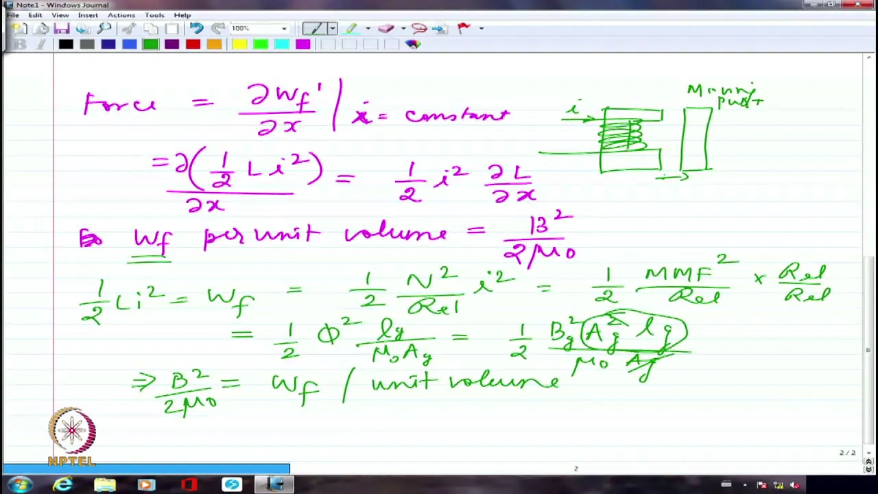
Electromechanical Energy Conversion-III
14.8K
This section introduces stepper motors as singly excited rotating machines. It explains the operating principle based on minimum reluctance: when a stator pole pair is excited, the ferromagnetic rotor aligns with those poles. Sequential excitation of different pole pairs causes step-by-step rotation. The step angle equals the difference between rotor and stator pole pitches—for example, 4-pole rotor (90° pitch) with 6-pole stator (60° pitch) yields 30° step angle. The section contrasts stepper motors with larger machines like synchronous and induction motors, noting that steppers are rugged but limited to smaller ratings (typically up to 1 kW).
Click to watch →
Deep Dive
The basic concept of rotational feedback and how quadrature optical encoders generate pulses to determine position and direction.

Understanding and using quadrature encoders - The Byte Sized Engineer | DigiKey
16K
Quadrature encoders use two phase-shifted square wave signals (typically 90° out of phase) to track rotational position and direction; by reading both signals simultaneously, a microcontroller can determine not only how far a shaft has rotated but also whether it is spinning clockwise or counterclockwise, with higher resolution achieved by increasing the number of pulses per revolution.
Click to watch →

06 Optical Sensors, Light Modulation, Noise Filtering, and Optical Encoders
1.3K
Optical encoders count lines on gratings for digital position measurement. Basic encoders produce pulses but cannot determine direction. Quadrature encoding uses two sensors 90° apart, producing phase-shifted signals that reveal direction. The A and B signals are decoded by logic circuits to produce direction and position outputs. Reference marks (index signals) provide absolute position by detecting unique patterns on the scale.
Click to watch →

Así funcionan los encoder de cuadratura
1.7K
This segment explains the fundamental principle of quadrature encoders. The KY-040 requires 20 mechanical steps for one full rotation. Encoders generate square wave signals on outputs A and B that are phase-shifted by 90 degrees. This phase shift enables direction detection: the sequence of LED activation changes based on rotation direction. The number of pulses per unit time allows calculation of rotational speed. An encoder delivers pulse sequences in two different switching orders—one for each rotation direction—enabling bidirectional position and direction tracking.
Click to watch →

How to use encoders (Optical, Hall Effect, Quadrature)
135K
Encoders measure angular position through rotating discs and sensors. Single-phase encoders detect rotation but cannot determine direction. Quadrature encoders use two sensors 90 degrees out of phase to enable bidirectional detection. Optical encoders employ infrared LEDs and receivers with slotted discs, producing square wave outputs where high states indicate light passing through slots. Magnetic encoders use Hall effect sensors detecting alternating magnetic domains on spinning discs. The phase difference between channels enables direction determination—clockwise when B is high, counterclockwise when B is low. Interrupt-driven microcontroller programming processes these signals for accurate pulse counting and RPM calculation.
Click to watch →

EE442 Review 1
127
Optical encoders convert rotational/linear motion to digital pulses using slitted discs between emitters and detectors. Channel A and B outputs provide quadrature signals with 90-degree phase shift (one-quarter cycle out of phase). Four distinct states (S1: A=1,B=0; S2: A=1,B=1; S3: A=0,B=1; S4: A=0,B=0) enable unambiguous direction detection. Counterclockwise rotation follows S1→S2→S3→S4→S1; clockwise follows S1→S4→S3→S2→S1. An N-line encoder provides 4N counts per revolution, enabling precise position measurement. Each count represents 360/(4N) degrees of rotation.
Click to watch →
Deep Dive
The core theoretical differences between open-loop systems (sending commands without verification) and closed-loop feedback systems.

Stability of Closed Loop Control Systems
271.5K
Open-loop control systems do not use feedback to determine if the system has met its desired state; they don't observe or sense the output. In contrast, closed-loop systems use feedback of the output state to alter the input. The key difference depends on what you label as the reference signal and what is the output. A system can be considered open-loop if the reference doesn't depend on the output of the plant.
Click to watch →
CONTROL SYSTEM - 1 OPEN LOOP & CLOSED LOOP SYSTEM - TAMIL
61.1K
Open-loop systems apply input without feedback, while closed-loop systems use feedback to compare actual output with desired output. Open-loop systems have a simple input-to-output structure with no feedback path. Closed-loop systems include a feedback mechanism that continuously monitors output and adjusts control actions to minimize error. The key difference is that closed-loop systems can compensate for disturbances and maintain desired output despite external variations, making them more suitable for applications requiring precise control.
Click to watch →
![LAZO ABIERTO y LAZO CERRADO ✅ [Sistemas de CONTROL] #009](https://i.ytimg.com/vi_webp/CxGFoeJ7SD8/maxresdefault.webp)
LAZO ABIERTO y LAZO CERRADO ✅ [Sistemas de CONTROL] #009
161.7K
In control systems, an open-loop system controls a process based on pre-programmed instructions without using feedback from the output, making it simple and inexpensive but unable to compensate for disturbances or variations; conversely, a closed-loop (feedback) system continuously monitors the output using sensors, compares it against a desired setpoint, and automatically adjusts the control action to maintain the desired value, providing better performance and disturbance rejection but requiring careful controller tuning to prevent oscillations and instability.
Click to watch →

TEORÍA DE CONTROL- Sistemas de control a lazo abierto y lazo cerrado
175.5K
Control systems are classified into two types based on feedback: open-loop systems operate without sensors and cannot verify if outputs match desired values, making them simpler and cheaper but less accurate; closed-loop systems use sensors to continuously monitor outputs, calculate error (desired minus actual), and adjust accordingly, making them more precise and robust against disturbances but more complex and expensive.
Click to watch →

【이론】 제어공학 01강(p.02~05)_1장 자동 제어계의 개요(제어계의 기본 구성, 자동 제어계의 분류)
20.7K
Open-loop control systems (개회로 제어계) lack feedback mechanisms and simply execute commands without monitoring results. Using an air conditioner example: if you set it to 20°C but it outputs 25°C, there is no correction mechanism—the system just continues operating as instructed. Closed-loop control systems (폐회로 제어계), also called feedback control systems, include feedback loops that compare actual output with desired input and make corrections. When the air conditioner outputs 25°C instead of the desired 20°C, the feedback loop detects this error and adjusts the system to reduce the temperature by 5°C, achieving the correct output.
Click to watch →
Deep Dive
Basic mechanical design concepts, such as shaft alignment, coupling methods, and the significance of structural rigidity in motion systems.
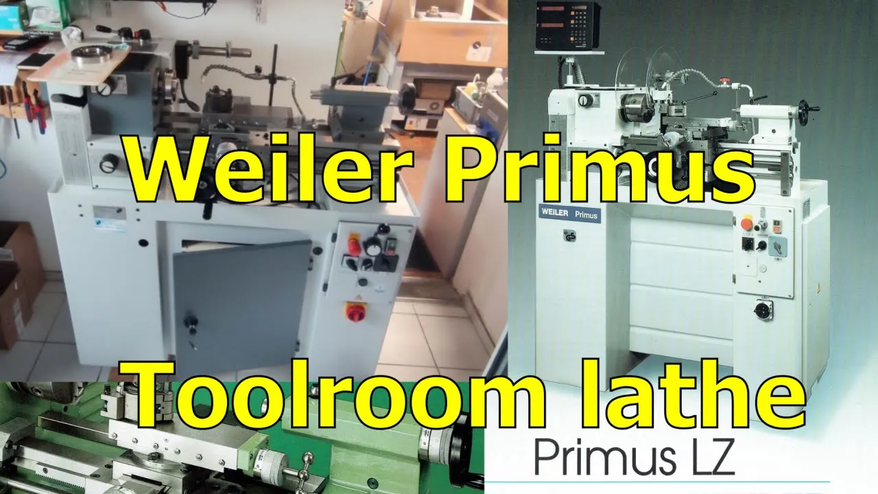
Toolroom lathe: Weiler Primus
92K
Machine bed design fundamentally determines structural rigidity and machining accuracy. The Wier Primus employs box ways with two hardened rails bolted to the casting, providing superior rigidity compared to diagonal webbing designs. Box ways offer wide bearing surfaces handling side forces effectively but require manual adjustment for wear compensation. Prismatic ways offer self-adjusting properties as they drop onto worn surfaces while maintaining zero play. Through-hardened rails made from tool steel provide long service life when properly maintained with regular wiper inspection using 10-micron shim stock.
Click to watch →

DESIGN OF SHAFT ON RIGIDITY BASIS|SHAFT DESIGN |SHAFT RIGIDITY DESIGN
553
Shaft design based on rigidity involves calculating the shaft diameter to ensure that lateral deflection does not exceed permissible limits (using δ = WL³/(3EI) where I = πd⁴/64) and that torsional angle of twist remains within acceptable ranges (using θ = TL/(GJ) where J = πd⁴/32), with the limiting values determined by the specific application requirements.
Click to watch →

Lecture - 34 Design of Shafts
112.7K
Stiffness-based design ensures shafts don't deflect excessively under operational loads. Three methods calculate deflection: simple integration, moment-area, and energy methods. For simply supported beams with central load, Δmax = PL³/(48EI). Torsional rigidity uses θ = TL/(GJ). Allowable deflections range from 0.5° to 3° per meter depending on application—machine tools require stricter limits. Stiffness design typically yields larger diameters than strength-based design. The design process involves setting allowable limits, calculating required dimensions, and selecting standard sizes.
Click to watch →

Linear/Gantry Milling Machine LIVE Forum and Q&A
4.1K
Proper machine setup requires tramming the spindle to ensure perpendicular alignment with machine axes, using indicators and adjustable clamps. Machines can operate in linear mode (bed sections bolted together) or gantry mode (beds separated with rails on both sides). Gantry configuration provides superior rigidity by supporting the workpiece on both sides, doubling the effective milling envelope compared to linear mode. Maximum unsupported reach is limited by spindle-to-bed distance, making configuration selection critical for specific applications.
Click to watch →

Лодка 12 метров которую я построил своими руками... Лодка которая пошла и мною испытана...
13.2K
This segment explains the critical importance of structural rigidity in boat construction, especially for 12-meter boats. The creator details how to use online flexing calculators to design proper bow geometry, comparing their 50cm height design with factory boats' 70cm height starting from 2m. The segment covers the balloon system method for creating rigidity using plywood strips tested under heavy loads, and explains how to join standard plywood sheets (2.2m long) using metal angles and cross-bracing to create a monolithic structure.
Click to watch →
Prerequisite Knowledge
- Concept 01Fundamental operating principles of standard stepper motors, including step angles, phases, and how magnetic coils are energized.
- Concept 02The basic concept of rotational feedback and how quadrature optical encoders generate pulses to determine position and direction.
- Concept 03The core theoretical differences between open-loop systems (sending commands without verification) and closed-loop feedback systems.
- Concept 04Basic mechanical design concepts, such as shaft alignment, coupling methods, and the significance of structural rigidity in motion systems.
Subsequent Learning
- Step 01Implementation and mathematical tuning of PID (Proportional-Integral-Derivative) loop algorithms to minimize positional error and oscillation.
- Step 02Field-Oriented Control (FOC) and vector control algorithms for stepper motors to improve efficiency and reduce noise.
- Step 03Integrating DIY closed-loop stepper motors into multi-axis motion platforms, such as 3D printers or desktop CNC routers, to prevent missed steps.
- Step 04Evaluating performance metrics, such as torque-speed curves, thermal characteristics, and power consumption differences between open and closed-loop operation.
Motor Prep
Plate Build
Next Steps
Motor Prep
0:00Playing Section
- 1
Extends stepper motor shaft with drilled coupling.
- 2
Attaches plastic gear for encoder integration.
Diminishing Returns Compared to Dedicated Servo and Integrated Closed-Loop Systems
While retrofitting a standard stepper motor with an encoder is an educational project, critics argue it is rarely practical or cost-effective for production environments. Custom-machining parts and tuning DIY PID loops introduces significant mechanical and software complexity, increasing the risk of resonance and system failure. Furthermore, standard stepper motors have a high pole count, causing their torque to drop sharply at higher speeds, which inherently limits the performance gains of a closed-loop system. For most applications, purchasing off-the-shelf integrated closed-loop stepper motors (hybrid servos) or native brushless DC (BLDC) servo motors is more economical. These commercial alternatives come factory-tuned, offer superior high-speed torque, and eliminate the compounding tolerances and assembly labor associated with DIY conversions.
Deep Dive
Implementation and mathematical tuning of PID (Proportional-Integral-Derivative) loop algorithms to minimize positional error and oscillation.

PID Tuning with the Ziegler-Nichols Method: A Tutorial
377.6K
The Ziegler-Nichols method provides two empirical approaches for determining PID controller gains: the first method uses the step response curve's inflection point to calculate L (distance from origin to tangent) and T (vertical distance), then applies formulas (KP=0.9T/L, KI=1.2T/L, KD=0.075L); the second method involves increasing proportional gain until the system exhibits sustained oscillations at critical gain Kcrit and period Pcrit, then using formulas (KP=0.5Kcrit, KI=1/(1.2Pcrit), KD=0.125Pcrit) to determine controller parameters. Both methods are simple to implement but have limitations and work best for certain transfer functions.
Click to watch →

PID Controller Tuning in Simulink/MATLAB Using Ziegler-Nichols method
10.1K
The Ziegler-Nichols tuning method is an experimental, data-driven approach for determining initial PID controller parameters without requiring a mathematical model of the plant; it involves implementing a proportional controller and increasing its gain until stable oscillations (marginally stable system) are observed, then measuring the critical gain (KC) and critical period (L) of oscillations to compute PID parameters using the formulas: KP = 0.6 × KC, TI = 0.5 × L, and TD = 0.125 × L.
Click to watch →

PID controller Zeigler-Nichols Tuning Method
22.6K
The Ziegler-Nichols tuning method is a systematic approach for determining PID controller parameters (Kp, Ki, Kd) by first finding the critical gain (Kc) and critical period (Tc) through Routh-Hurwitz stability analysis, then applying specific formulas: for P control, Kp = Kc/2; for PI control, Kp = 0.45Kc and Ti = Tc/2; for PID control, Kp = 0.6Kc, Ti = Tc/2, and Td = Tc/8.
Click to watch →

B.Tech S6 | Linear Control System M3 - M4 | Franklin's Lectures | KTU
828
The Ziegler-Nichols method provides a systematic approach to PID controller tuning. The process involves: setting integral and derivative gains to zero, gradually increasing proportional gain until oscillation begins, recording the ultimate gain (KU) and ultimate period (TU), then applying Ziegler-Nichols rules to determine controller parameters. For P controller: KP = 0.5KU. For PI controller: KP = 0.45KU, KI = 0.54KU/TU. For PID controller: KP = 0.6KU, KI = 2KU/TU, KD = 0.125KU*TU. This method provides a practical starting point for controller design.
Click to watch →
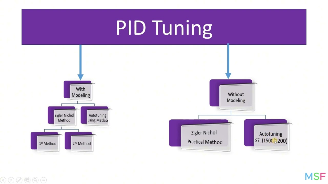
PID_4 (PID Tuning Methods) شرح ال
229
PID tuning determines optimal values for Proportional (Kp), Integral (Ki), and Derivative (Kd) parameters to achieve desired system response. Methods are classified into model-based (using mathematical equations) and practical approaches. Model-based methods are rarely applicable in real-world scenarios, where practical methods are used approximately 95% of the time. The Ziegler-Nichols First Method (Step Response) involves applying a step input, identifying the inflection point, drawing a tangent line, and determining system delay (τ) and steady-state gain (K). Parameters are calculated as: Kp = 0.5×(T/τ) for P-only, Kp = 0.45×(T/τ) and Ki = 1/(1.2×τ) for PI, and Kp = 0.6×(T/τ), Ki = 0.5/τ, Kd = 1.25×τ for PID. The Second Method (Root Locus) uses the root locus plot to find the intersection with the imaginary axis, determining critical gain (Kcr) and frequency (ωcr), then calculating PID parameters based on these values.
Click to watch →
Deep Dive
Field-Oriented Control (FOC) and vector control algorithms for stepper motors to improve efficiency and reduce noise.

This Indian company is challenging Chinese dominance where it matters! | हिंदी में
44.4K
Electronic Speed Controllers (ESCs) use either trapezoidal control or field-oriented control (FOC) to regulate motor speed. Trapezoidal control is simpler but produces more electromagnetic noise and has lower efficiency. FOC-based ESCs reduce electronic noise significantly and achieve higher efficiency compared to trapezoidal controllers. Vector Technologies has developed FOC-based ESCs that have completed 1000-hour testing and are preparing for market release, representing an advancement in drone propulsion control technology.
Click to watch →
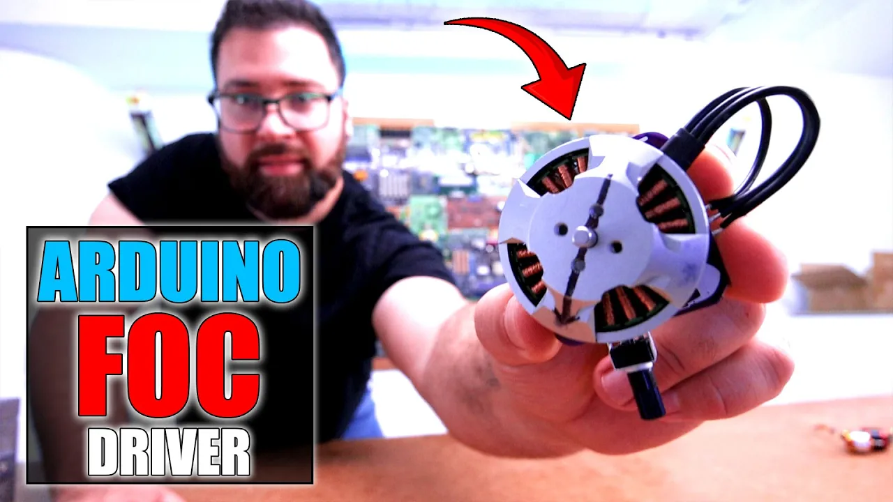
FOC Driver + Feedback Magnetic Sensor - Arduino
77K
Field-Oriented Control (FOC) enables precise control of brushless motors by using magnetic encoders for feedback, allowing the motor to maintain its position even when manually displaced; the control algorithm calculates the electrical angle from the sensor's mechanical angle reading, then applies proportional-Derivative (PD) control to generate the appropriate PWM signals for each motor phase, achieving smooth and responsive motor behavior similar to stepper motors but with the efficiency of brushless motors.
Click to watch →

TMS320F28379D, LAUNCHXL-F28379D - Vector control (Indirect Field Oriented) for 3ph Induction Motor
1.5K
Indirect field-oriented vector control for three-phase induction motors uses an encoder to measure rotor position, estimates flux through slip calculation, and controls motor torque and flux separately by transforming three-phase currents into dq0 coordinates, enabling precise speed control despite the inherent slip that causes asynchronous motor speed to differ from synchronous speed.
Click to watch →

Teaching Old Motors New Tricks - Part 1
266.8K
Field-Oriented Control (FOC) is a unified motor control technique that synchronizes the stator current vector to be 90° quadrature with the rotor flux vector, enabling maximum torque per amp operation across various motor types including permanent magnet AC, induction, and interior permanent magnet motors; FOC achieves this by transforming three-phase currents into a rotating reference frame (d-q axis) where the d-axis component controls flux and the q-axis component controls torque, allowing precise torque control similar to DC motor behavior while maintaining sinusoidal current waveforms.
Click to watch →

Vector control (motor)
10.9K
Vector control, also known as field-oriented control (FOC), is an advanced variable-frequency drive method that treats three-phase AC motor currents as two orthogonal components—one representing magnetic flux and the other representing torque—allowing AC motors to be controlled similarly to separately excited DC motors. This technique, pioneered by Technical University of Darmstadt starting in 1968 and further developed by Technical University of Brown, uses the Park transformation (originally conceptualized by Robert H. Park in 1929) to convert time-varying motor equations into time-invariant forms, enabling independent control of flux and torque for improved dynamic performance. FOC employs proportional-integral controllers and pulse-width modulation to generate precise voltage references, and can operate in either open-loop sensorless mode or closed-loop mode with speed sensors, offering superior efficiency, reduced motor size, and enhanced dynamic response compared to traditional scalar volts-per-hertz control methods.
Click to watch →
Deep Dive
Integrating DIY closed-loop stepper motors into multi-axis motion platforms, such as 3D printers or desktop CNC routers, to prevent missed steps.

Stepperonline CL86Y: Bench Testing with Centroid Acorn
47.8K
Closed-loop stepper motor systems, such as the StepperOnline CL86Y driver paired with a 12 Newton-meter motor and Centroid Acorn controller, offer significant advantages over open-loop systems by continuously monitoring motor position through encoders and generating alarms when the motor cannot follow commanded movements, thereby preventing missed steps and protecting workpieces; these systems can achieve high speeds (tested at over 3,600 RPM) while maintaining accuracy, with most settings configurable via dip switches and optional programming software.
Click to watch →

Improving a good CNC machine - Sainsmart Genmitus Proverxl 4030 V2 Review
59.1K
Closed-loop stepper motors in CNC machines incorporate feedback systems that continuously verify motor position, unlike open-loop systems which assume commands are executed correctly; this prevents missed steps during heavy cutting loads and enables higher speeds (up to 6000 mm/min) while maintaining precision, making them particularly valuable for CNC routers and mills where consistent accuracy is essential.
Click to watch →
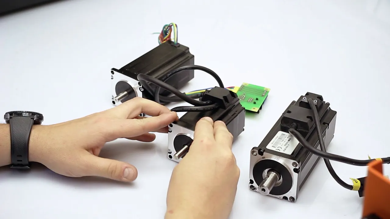
Обзор шаговых двигателей и серводвигателей для станков
108.7K
This section covers three types of stepper motors used in CNC machines. Standard stepper motors (57A 6/12) are most common for hobby machines due to low cost and simple 4-wire connection with step/dir protocol. Stepper motors with encoders (hybrid motors) provide closed-loop control, compensating for torque drop at high speeds and eliminating low-speed vibrations. They include alarm outputs for safety when steps are missed. Servo motors differ fundamentally as asynchronous motors with constant torque across speeds, offering maximum 3000 RPM and extensive configuration options including PID tuning. Motor selection depends on application: standard stepper for wood/plastic at moderate speeds, hybrid stepper for higher speeds (4500-5000 mm/min), and servo motors for maximum performance and machine class elevation.
Click to watch →
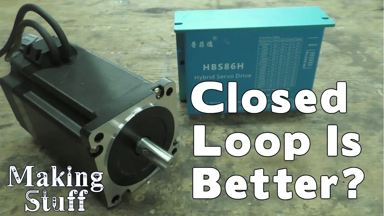
Closed Loop Stepper Motors for CNC machines
198.8K
This video provides a comprehensive examination of closed-loop stepper motor systems, contrasting them with traditional open-loop motors used in 3D printing and hobby CNC applications. Key topics include: (1) the fundamental difference of bidirectional communication enabled by motor-mounted encoders; (2) hybrid servo controller functionality that verifies step completion and triggers alarms on missed steps; (3) performance advantages including dynamic amperage control, voltage flexibility (AC/DC support), and significantly reduced heat generation; (4) practical demonstrations showing temperature behavior, mechanical overload response, and encoder disconnection effects; (5) comprehensive safety features including automatic alarm triggering, error mode activation, and integration with CNC emergency stop systems. The content illustrates how closed-loop technology enables more reliable, efficient, and safe motor control compared to conventional stepper motor implementations.
Click to watch →

Watch Me Build Closed-Loop CNC Electronics in 25 Minutes
142.5K
This comprehensive segment explains the implementation of closed-loop motor systems with encoder feedback and demonstrates complete CNC system operation. Closed-loop stepper motors incorporate encoders on their shafts that provide feedback confirming actual rotation matches commanded output, ensuring precise positioning. The system uses three closed-loop drivers powered by 60-volt supplies and one open-loop driver powered by 48 volts for the Z-axis. Encoder cables require shielding and should be separated from motor cables to prevent electromagnetic interference. The video demonstrates soldering encoder connectors to panel-mounted receptacles using the wire combing technique for organized cable routing. Each encoder connector requires careful alignment with matching notches and secure fastening to prevent disconnection during operation. The final assembly includes preparing and soldering 50 feet of motor cable and encoder cable with heat shrink tubing protecting soldered sections. Dip switches on each driver control microstepping and current settings, requiring adjustment based on specific motor requirements. Voltage testing verifies power supply outputs before powering on the complete system. The demonstration shows jogging axes using keyboard arrow keys with audible motor operation confirming successful movement. Output signals are configured through Mach3 Ports and Pins settings, assigning outputs to specific ports and pins with active-low configuration. One relay controls both spindle directions while another controls both flood and mist functions simultaneously. Input capabilities include limit switches, home switches, and e-stops connected through dedicated input connectors. Ground connectors are essential for completing all electrical circuits. Analog voltage inputs (0-10V) enable PWM-controlled spindle speed adjustment.
Click to watch →
Deep Dive
Evaluating performance metrics, such as torque-speed curves, thermal characteristics, and power consumption differences between open and closed-loop operation.
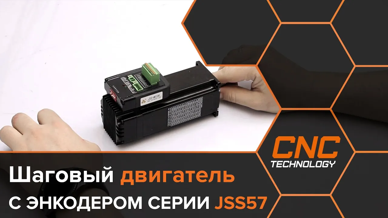
Обзор шаговых двигателей с энкодером.
11.2K
This segment presents detailed torque-speed comparisons between closed-loop and open-loop stepper motors. The GSS 57 P2N maintains nearly constant torque (2.1 N·m) from 0 to 1000 RPM, while the NEMA 23 motor drops from 2.4 N·m to just over 1 N·m at 1000 RPM. The 57 612 motor shows even more dramatic torque degradation, dropping to 2 N·m at 600 RPM. These results demonstrate that closed-loop motors provide significantly better performance for CNC applications requiring consistent cutting forces at higher speeds.
Click to watch →

Vergleich von Schrittmotoren - Teil 2
30.1K
This comprehensive video demonstrates the performance differences between open-loop and closed-loop stepper motors through practical testing. Open-loop motors (30 euros) exhibit resonance phenomena and cannot maintain acceleration beyond 200mm/s², eventually stopping. Closed-loop motors (100-110 euros) operate quietly, achieve accelerations of 2000mm/s², and reach maximum speeds of 8000mm/minute (2000 RPM). The practical test uses a 320mm machine moving a 20kg load, revealing real-world limitations. Power consumption reaches 90-100 watts at full speed, with the motor remaining touchable at 45-50°C after 37 minutes. The video concludes that closed-loop systems provide significantly better reliability and performance for CNC applications.
Click to watch →

MKS SERVO42C Closed-Loop Stepper: Tests vs Servo with Field-Oriented Control and TMC2209 Open-Loop
184.2K
This video compares three motion control systems—MKS SERVO42C closed-loop stepper, generic NEMA17 open-loop stepper with TMC2209 driver, and a custom servo system—through thermal, acceleration, and speed tests. The results show that while closed-loop steppers offer quiet, energy-efficient operation suitable for applications like camera dollies and timelapse sliders, they perform poorly in acceleration and speed tests compared to both the open-loop stepper and the servo. The open-loop stepper provides a simple, low-cost solution but wastes power when stationary and cannot match servo speeds. The servo system delivers the highest performance in terms of speed and acceleration but requires complex control loop tuning. Each system has distinct advantages depending on the application requirements.
Click to watch →

What's the best NEMA23 Stepper/Servo? | Electronic Leadscrew Part 24
160.9K
This video demonstrates that digital stepper drivers significantly outperform analog drivers in torque output and smoothness, while closed-loop stepper motors with encoders do not consistently outperform similarly-rated open-loop steppers; however, integrated servo motors like ClearPath provide substantially higher peak torque capabilities (up to nearly 6 Nm) compared to steppers (typically 2-4 Nm), making them superior for applications requiring high torque during intermittent loads like cutting operations.
Click to watch →
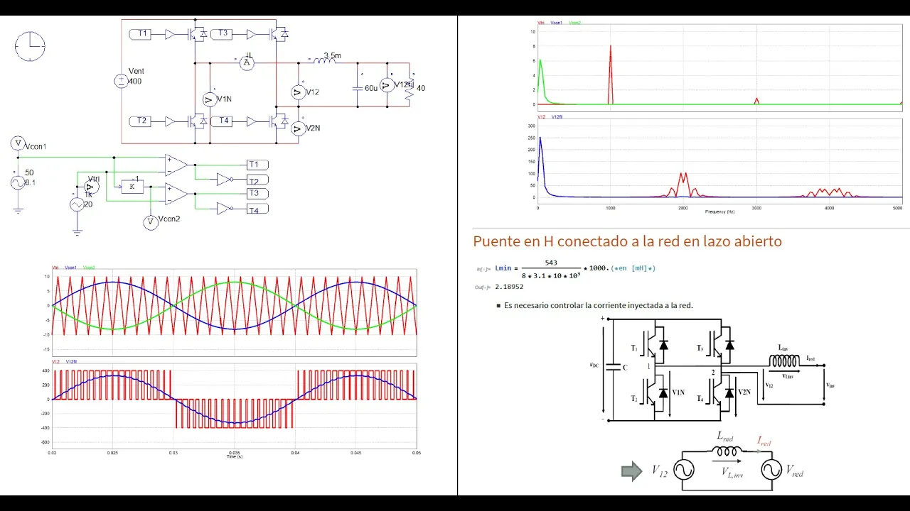
Electrónica de Potencia - Inversor monofásico simulado en PSIM, 17/11/2020
8.4K
In open-loop operation, the inverter injects current without feedback, resulting in poor power factor. Closed-loop control uses feedback to maintain injected current in phase with grid voltage, achieving unity power factor. The control system measures actual current, compares it with a reference, and adjusts inverter output to minimize error. This requires a current sensor and control algorithm (typically PI controller). The PI controller is preferred because it eliminates steady-state error. The controller has proportional gain (K_p) and integral time constant (τ_n), with the transfer function K_p(1 + sτ_n)/(sτ_n).
Click to watch →
Motor Prep
Plate Build
Next Steps
Motor Prep
0:00- 1
Extends stepper motor shaft with drilled coupling.
- 2
Attaches plastic gear for encoder integration.
Diminishing Returns Compared to Dedicated Servo and Integrated Closed-Loop Systems
While retrofitting a standard stepper motor with an encoder is an educational project, critics argue it is rarely practical or cost-effective for production environments. Custom-machining parts and tuning DIY PID loops introduces significant mechanical and software complexity, increasing the risk of resonance and system failure. Furthermore, standard stepper motors have a high pole count, causing their torque to drop sharply at higher speeds, which inherently limits the performance gains of a closed-loop system. For most applications, purchasing off-the-shelf integrated closed-loop stepper motors (hybrid servos) or native brushless DC (BLDC) servo motors is more economical. These commercial alternatives come factory-tuned, offer superior high-speed torque, and eliminate the compounding tolerances and assembly labor associated with DIY conversions.
Fundamental operating principles of standard stepper motors, including step angles, phases, and how magnetic coils are energized.
The basic concept of rotational feedback and how quadrature optical encoders generate pulses to determine position and direction.
The core theoretical differences between open-loop systems (sending commands without verification) and closed-loop feedback systems.
Basic mechanical design concepts, such as shaft alignment, coupling methods, and the significance of structural rigidity in motion systems.
Implementation and mathematical tuning of PID (Proportional-Integral-Derivative) loop algorithms to minimize positional error and oscillation.
Field-Oriented Control (FOC) and vector control algorithms for stepper motors to improve efficiency and reduce noise.
Integrating DIY closed-loop stepper motors into multi-axis motion platforms, such as 3D printers or desktop CNC routers, to prevent missed steps.
Evaluating performance metrics, such as torque-speed curves, thermal characteristics, and power consumption differences between open and closed-loop operation.
345.7K views1.7Klikes4:08@KrisTemmermanNPOriginal Release: 2015-01-16
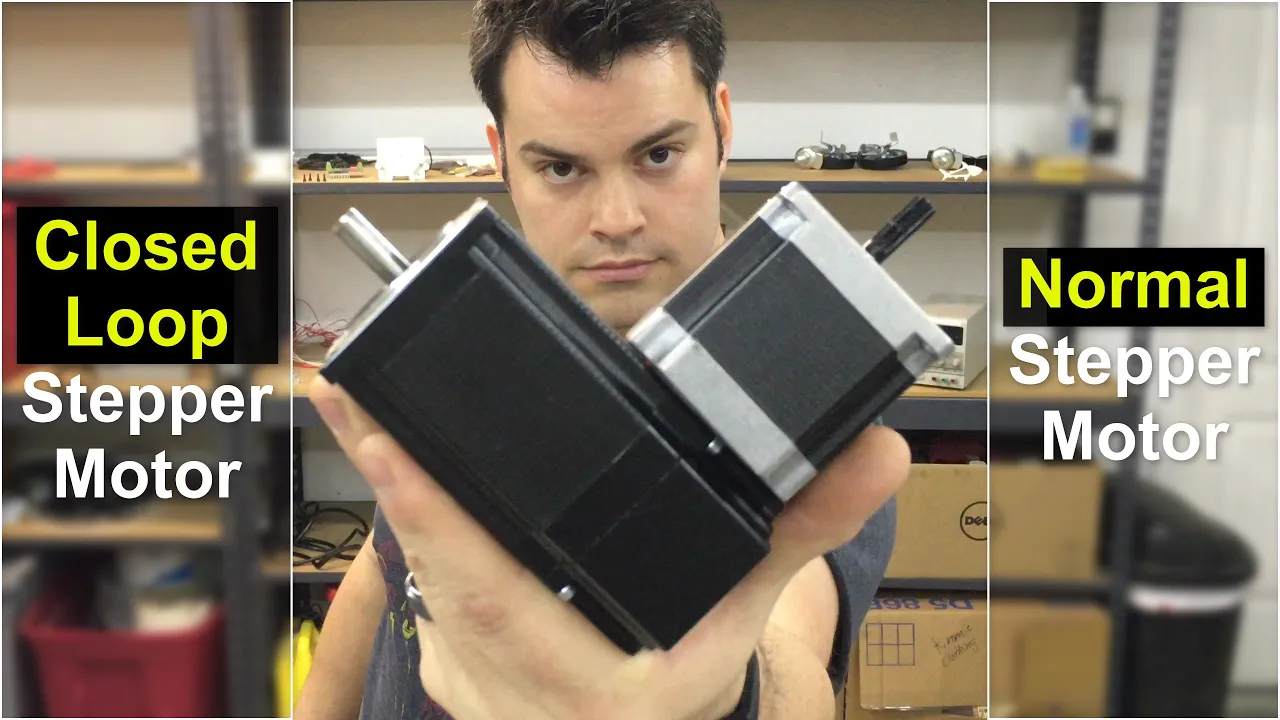
Hi, my name is Chris. In this video, I'm going to convert a normal stepper motor to a closed loop stepper motor.
I'm going to do this by connecting an optical rotary encoder to the shaft of the stepper motor.
For that, I'm going to use some of these cheap plastic gears. The first thing I need to do is extend the shaft of the motor so I have a little bit more room to attach the gear.
[Music] I should use a coupling, but I'm just going to drill a hole in my new shaft, slide it over the old one, and use a set screw to hold it all together.
[Music] Here I'm designing a plate to hold the motor and the rotary encoder. I'm going to use my CNC to spot drill the holes and cut out the plate.
[Music] Heat. Heat.
[Music] [Laughter] [Music] [Music] To finish the plate, I just have to drill some holes and tap some threads to hold the motor.
[Music] What's left to do is do some cleaning up, putting everything together, and hoping I didn't make any mistakes.
[Music] [Music] Now I have to hook up the motor and the rotary encoder to a microcontroller.
But that will be something for the next video. Hope you enjoyed it and thanks for watching.
Up Next
10:03
Closed-Loop vs Open-Loop Stepper Motors: A Comparative Analysis
@CountryAireDesign
174.6K views•2019-01-01

30:32
Ultrasonic Transducers: Resonant Frequency Measurement and Horn Design
@imajeenyus42
229.9K views•2017-02-22

2:51
Building a Rocker-Bogie Rover for Kids: Design and Control
@KrisTemmermanNP
151.3K views•2019-04-01

33:39
How a Student's Question Saved a NYC Skyscraper from Collapse
@veritasium
22.8M views•2025-04-26
Related Study Plans & Knowledge Roadmaps
Structured learning paths in Engineering
engineering
Building Acoustic Levitators: Physics & Arduino
01The Physics of Sound and Standing Waves
02Piezoelectric Transducers and H-Bridge Drivers
03Arduino Programming: Generating 40 kHz Signals
+ 2 more learning modules
14h5 modules
Explore Roadmap
engineering
Building Peltier Cloud Chambers: Particle Tracks
01Cosmic Rays & Cloud Chamber Physics
02Thermoelectric Cooling (TEC) Fundamentals
03Custom Liquid-Cooling Loop Design
+ 2 more learning modules
18h5 modules
Explore Roadmap
engineering
Yagi-Uda Antennas: Modeling, Build & VNA Test
01Introduction to RF and Antenna Fundamentals
02Yagi-Uda Antenna Design Principles
03Antenna Modeling and Simulation in 4NEC2
+ 2 more learning modules
18h5 modules
Explore Roadmap
engineering
ECG Monitor Design: Op-Amps, Filters & Noise
01Electronics & Breadboard Basics
02Op-Amps and Instrumentation Amplifiers
03Bioelectricity and ECG Fundamentals
+ 2 more learning modules
18h5 modules
Explore Roadmap