A rocker-bogie suspension system uses interconnected pivoting arms to maintain all wheels on the ground during rough terrain traversal; this design keeps the vehicle's seat balanced and upright by distributing weight evenly across the chassis through a differential bar connecting opposing rockers, allowing each wheel to adapt independently to uneven surfaces while providing stable transportation.
Building a Rocker-Bogie Rover for Kids: Design and Control
Added:Deep Dive
Basic Arduino programming, including uploading sketches, using the Arduino IDE, and understanding digital and analog I/O pins.
Ардуино #2. Динамическая индикация. Подключаем кнопки, потенциометр, динамик и ключ на мосфете.
126.6K
Arduino is a microcontroller-based platform for developing electronic circuits with software control. Programs called 'sketches' are written on a computer and uploaded via USB cable. The Arduino Uno features 14 digital I/O pins (can function as inputs or outputs) and 6 analog input pins. Pins 0 and 1 are reserved for serial communication and should be avoided during sketch upload. The board can be powered by USB, a USB charger, or a 7-12V DC power source. Understanding these fundamentals is essential before building projects.
Click to watch →

Arduino Coding for Beginners | How to Program an Arduino?
591.5K
Arduino IDE (Integrated Development Environment) is a free software used for writing, compiling, and uploading code to Arduino boards. It functions as a lightweight text editor where you write your code. The code written inside Arduino IDE is called an Arduino sketch. Arduino programming uses a language similar to C++ and is designed to be very easy to learn. The code is first compiled into machine-readable language and then uploaded to the Arduino board.
Click to watch →
تعلم برمجة الاردوينو | أساسيات كتابة كود الاردوينو
7.6K
This comprehensive lesson covers Arduino programming basics. The Arduino IDE integrates three components: Code Editor for writing code, Compiler for converting C/C++ to machine code, and Uploader for transferring code to the microcontroller. A sketch is divided into three sections: the top section for defining variables and constants, setup() for one-time initialization, and loop() for continuous execution. Key functions include pinMode() for configuring pins as INPUT or OUTPUT, digitalWrite() for setting pins to HIGH (5V) or LOW (0V), and delay() for pausing execution in milliseconds. A complete blinking LED example demonstrates these concepts: pinMode(led1, OUTPUT), digitalWrite(led1, HIGH), delay(1000), digitalWrite(led1, LOW), delay(1000). Code is uploaded via USB connection to the Arduino board.
Click to watch →
Arduinoya Giriş-Sıfırdan Arduino Öğreniyorum#1
51.4K
This section teaches Arduino IDE navigation and fundamental programming concepts. The IDE includes File menu for project management, Library Manager for adding external libraries, Tools menu for board and port selection, and Serial Monitor for debugging. Arduino programs use two main functions: void setup() for one-time initialization and void loop() for continuous execution. Pin configuration requires pinMode() to set pins as INPUT or OUTPUT. Digital output control uses digitalWrite() with HIGH (5V) or LOW (0V) states. The delay() function creates time delays in milliseconds (1000ms = 1 second). LEDs require current-limiting resistors to protect them from excessive current and extend operational lifespan.
Click to watch →

Arduino Programming Masterclass: From Basics to Libraries in 90 Mins
3.6M
The Arduino IDE enables writing and uploading code to boards. Available versions include Arduino IDE 1, Arduino IDE 2, and a web editor. Installation creates a sketchbook folder storing projects and libraries. The workflow involves: connecting via USB, selecting board type under Tools > Board, choosing COM port under Tools > Port, clicking Verify to compile and check errors, then clicking Upload. Every program requires void setup() (runs once for initialization) and void loop() (runs repeatedly forever). Variables store data using data types (boolean, byte, int, long, float, char), names, assignment operators (=), and initial values. Semicolons terminate statements. The Blink example demonstrates basic functionality by toggling the onboard LED.
Click to watch →
Deep Dive
Fundamental electronics concepts such as voltage, current, power sourcing, and the function of an H-bridge motor driver.

Ponte H do Nelson
3.8K
An H-bridge motor driver uses pairs of MOSFETs (both upper and lower) to control motor direction and speed through PWM signals, where adjusting the PWM duty cycle changes the average voltage applied to the motor, thereby controlling its speed; the system can be monitored using a multimeter to measure current and an oscilloscope to visualize the PWM waveform.
Click to watch →

Elektronika Instrumentasi Kendali Driver Motor H Bridge IRF Mosfet
4.6K
The H-Bridge motor driver is an electronic circuit named for its H-shaped configuration. It uses MOSFET transistors (IRF9530 P-channel and IRF540 N-channel) to control DC motors. The circuit requires a 1kΩ resistor and BD139 NPN transistor for control logic. The driver enables bidirectional motor control by switching MOSFET states based on transistor base signals, allowing current to flow through the motor in either direction. This fundamental circuit serves as the bridge between microcontrollers and motors, handling voltage level differences between low-voltage control signals and high-voltage motor power requirements.
Click to watch →
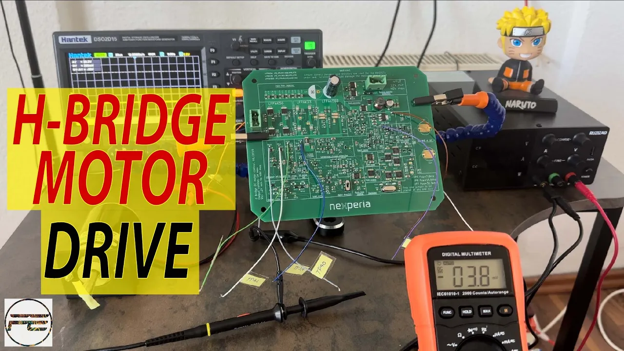
H-Bridge DC Motor Driver: Exploring the Inner Workings | Understanding H bridge DC Motor drive.
9.3K
An H-bridge (full bridge) is a switching network of four MOSFETs that creates bi-directional current and reversible voltage for DC motor control. The motor connects at the MOSFET junction, and switching them on/off with PWM varies average voltage to control speed. Direction changes by switching different MOSFET pairs: Q2+Q3 for forward, Q1+Q4 for reverse. The complete system includes: (1) Power supply accepting 12-48V with protection, (2) Clock/PWM generator with 4MHz oscillator and variable duty cycle, (3) PWM section with dead-time control, (4) High-side and low-side drivers with charge pumps for high-side MOSFETs, (5) H-bridge network with decoupling, snubbers, and gate resistors, and (6) Over-current protection that shuts down the bridge during faults.
Click to watch →
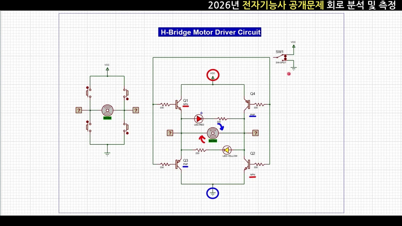
2026 전자기능사 공개문제1 동작 영상_H-Bridge Motor Driver 회로 분석
540
H-bridge motor driver circuits use transistors as electronic switches to control motor direction and speed. The circuit operates by rapidly switching transistors between cut-off (open switch) and saturation (closed switch) regions. In cut-off, no current flows; in saturation, maximum current passes with minimal resistance. Four switches form a bridge around the motor. By selectively turning on opposite pairs of switches, current flows through the motor in one direction for clockwise rotation, or the reverse for counterclockwise rotation. This bidirectional control enables precise motor positioning and speed regulation in robotics and automation systems.
Click to watch →
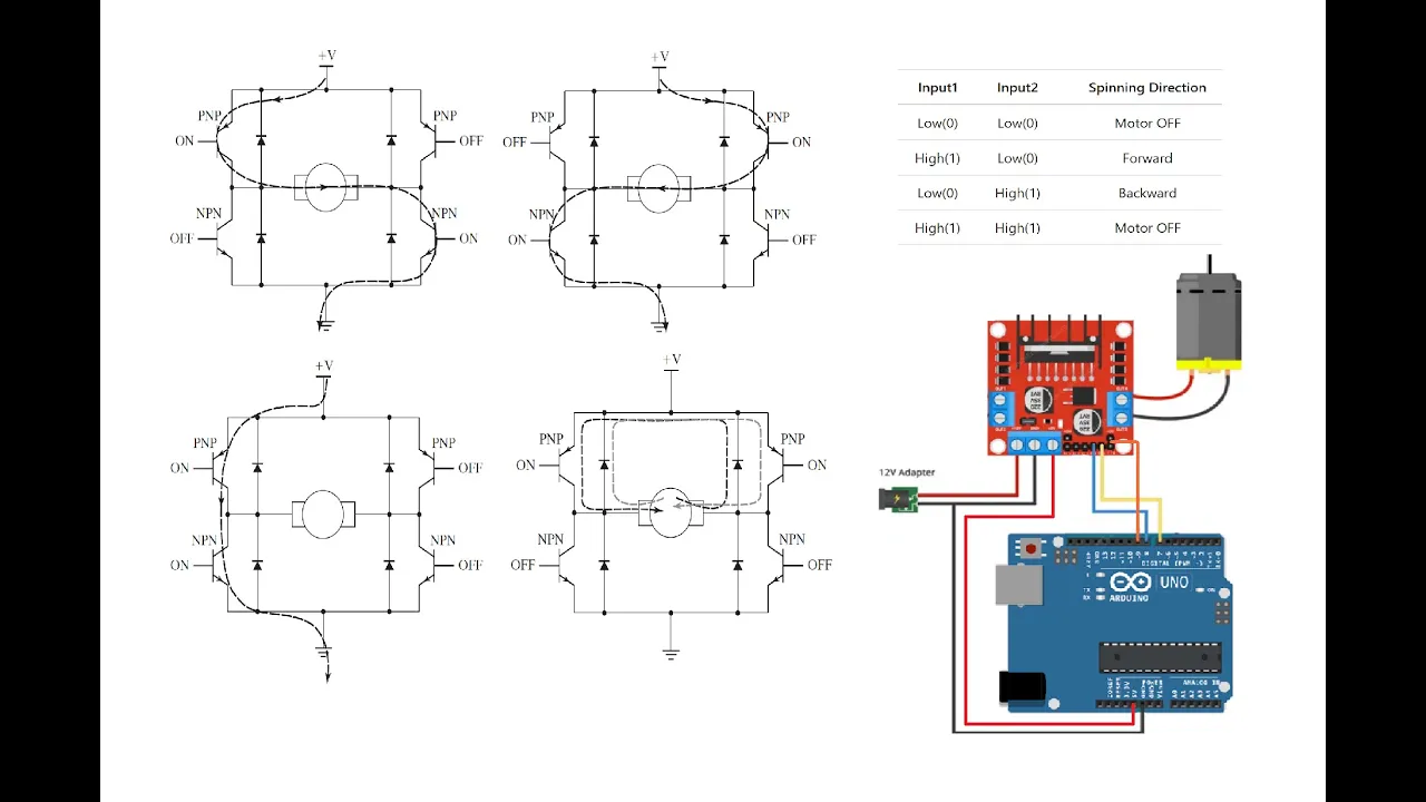
H Bridge Basics and Application, L298N Motor Driver
371
An H-bridge is an electronic circuit enabling bidirectional rotation of DC motors using four transistors (two PNP and two NPN) and four protective diodes. The motor connects between transistor junctions, with high and low voltage applied to opposite sides. Direction reversal occurs by selectively activating different transistor pairs: top-left and bottom-right transistors produce clockwise rotation, while top-right and bottom-left produce counterclockwise rotation. This bidirectional current flow reverses electromagnetic polarity in the motor's armature windings, changing torque direction. Modern motor drivers integrate this functionality into single chips, supporting multiple motors with built-in PWM speed control capabilities.
Click to watch →
Deep Dive
The physical concepts of center of mass, torque, and basic mechanical leverage, which govern how vehicle suspensions balance.

7 SORUDA TORK DENGE+KÜTLE MERKEZİ+BASİT MAKİNELER | PDF | AYT Fizik Sorularla Full Tekrar
13.6K
This segment covers two related concepts: center of mass location and lever system mechanics. First, an object can only be balanced at its center of mass; if it rotates away from a support point, the center of mass is not at that point. Second, in lever systems, force and distance are inversely related. When force advantage exists (applied force less than load), distance disadvantage occurs. Moving the fulcrum closer to the load increases force disadvantage but reduces distance disadvantage. This trade-off is fundamental to all lever systems.
Click to watch →

Kütle ve Ağırlık Merkezi - 3 | 88 Günde AYT Fizik Kampı | 31. Gün | 2025
202.4K
The center of gravity is the point where an object's entire weight can be considered to act. For suspended objects, the center of gravity must lie on the suspension string's line because gravitational force creates zero torque about the pivot. For irregular objects, the center of gravity is found experimentally by suspending from two points and marking plumb lines; their intersection is the center of gravity. For equilibrium, net torque about any point must be zero. When an object is balanced on a support point, the center of gravity must be at that point. For composite objects, total torque is the sum of individual torques (weight × perpendicular distance). Symmetrically placed parts with equal weights and distances have torques that cancel each other out.
Click to watch →

Kísérletek, amelyeket látni kell 2026.
1.5K
This section explains how to find and apply the center of mass and torque principles. The center of mass is the balance point where an object's mass is concentrated. For irregular objects like hammers, suspend from different points and mark plumb lines—their intersection reveals the center of mass. For uniform objects like meter sticks, the center of mass is at the midpoint. Torque equals force multiplied by distance from the pivot. For balance, torques on both sides must be equal, meaning heavier objects must be closer to the pivot. This explains lever mechanics and why short arms require more force than long arms.
Click to watch →
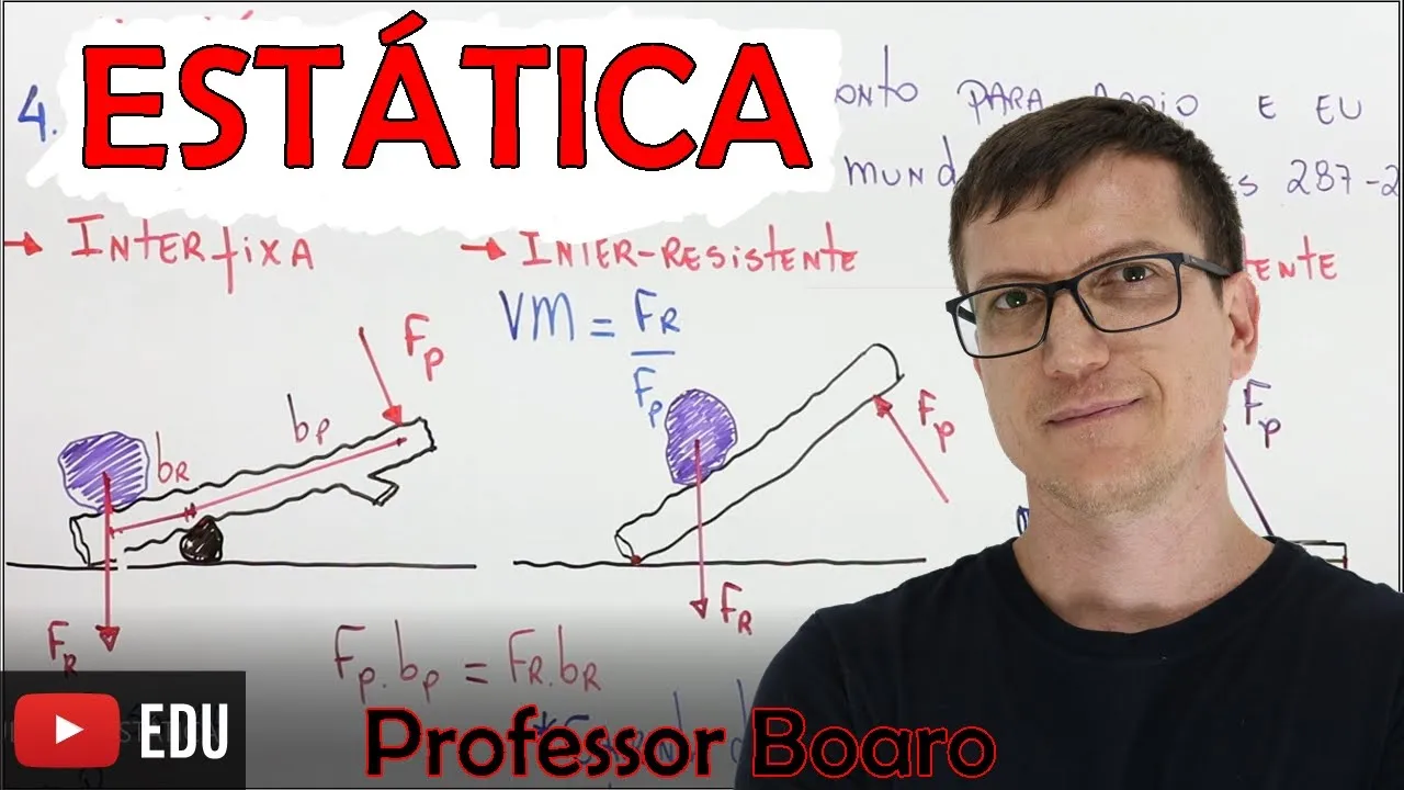
ESTÁTICA - MEGA AULA COMPLETA - Professor Boaro
216.9K
Levers are classified into three types based on fulcrum position: (1) Interfixa (fulcrum between effort and load, like scissors); (2) Interresistente (load between fulcrum and effort, like wheelbarrows); (3) Interpotente (effort between fulcrum and load, like human arms or tweezers). Mechanical advantage follows VMA = Fr/Fp = br/bp, where longer lever arms reduce required force. The center of mass (Xcm = Σmi×xi/Σmi, Ycm = Σmi×yi/Σmi) represents where total mass can be concentrated for motion analysis. The center of gravity coincides with center of mass near Earth's surface but differs for tall objects due to gravitational variation with height—lower sections experience stronger gravity, shifting center of gravity downward. Objects balance when external forces act through their center of gravity.
Click to watch →

Centro de masa 1: concepto
114.7K
The center of mass is the point on an object where applying a force causes no rotation, keeping it balanced. For two masses on a massless rod, balance occurs when the product of each mass and its distance from the pivot are equal (m₁d₁ = m₂d₂), following Archimedes' lever principle. This establishes the fundamental relationship between mass distribution and rotational equilibrium.
Click to watch →
Deep Dive
Familiarity with basic hand tools and prototyping materials for physical chassis assembly.

Tutorial video on assembling the PCS chassis.
3.8K
Essential tools for PCS chassis assembly include wire strippers, longnose pliers, plastic cutters, a file, scalpel, 15-25 WT soldering iron, cross-head screwdriver, and .9 Allen key. The first assembly step is fitting the motor by inserting the pinion end first, then pushing the back end into place. Bearings clip into the rear of the chassis. The gear is placed, the axle threaded through bearings and gear, and the Allen key holds it in place. For wire preparation, cut silicon wire in half, strip 8 mil on one end and 3 mil on the other, and twist to keep strands tight. Place ferals on the 8 mil end and bend wire over to secure them.
Click to watch →

How I Built a Handmade Chassis for my Turbo 1968 Chevy C10 Build
92.8K
Building a custom chassis from scratch is achievable with basic hand tools including a handheld plasma cutter and welder. Success requires progressive learning through hands-on experience, starting with simpler projects to build knowledge and skills. Three essential tools are needed: a welder, a grinder, and a plasma cutter. A decent workspace is necessary, though it doesn't need to be expensive. Mid-range tools are sufficient, allowing budget allocation toward vehicle parts. A metal bender or brake is needed for bending frame pieces, with larger pieces often bent at local metalworking shops. Successful builds require a clear vision and inspiration from existing projects, with research on platforms like Instagram and YouTube helping establish a baseline. Chassis design begins with key measurements: wheelbase and width between frame rails. The design process involves trial and error, with adjustments made during construction. A frame jig is crucial for securing the frame during construction to prevent measurement errors.
Click to watch →

Préparation pour l'atelier - La manivelle-cadre
1.4K
Students must be able to identify materials by name when they see them physically. The materials provided for the manivelle card include wood and metal. Students must also be familiar with the tools available, including: (1) Drill press (perceuse à colonne) - for making precise holes, (2) Band saw (scie à ruban) - for cutting wood, (3) Disc sander (ponceuse à disque) - for smoothing surfaces. Students should know both the names and basic functions of these tools to successfully complete the fabrication task.
Click to watch →

03. Ensambla tu PROTOBOARD para trabajar PROFESIONALMENTE con la ESP32
182
Essential tools for protoboard assembly include: scissors, a craft knife or scalpel, a metal ruler, packing tape, and a pen with pencil. The most important materials are two protoboards, which are the most economical option costing approximately 3 dollars each or less, totaling around 6 dollars for the project.
Click to watch →

Plate and Standoff Construction A simple 2D Method for Creating Accurate 3D parts
159
Material selection follows a progression: wood for initial prototyping due to speed and ease; aluminum (typically 3/16 inch) when weight becomes a concern; polycarbonate for strength with flexibility (caution needed as it can cause wheels to detach); and steel for maximum strength but significant weight. Standoff materials include 80/20 aluminum extrusion (strongest, commonly used for chassis), Churros (lighter alternative), and Thunder Hex. Effective assembly practices include pre-drilling motor mounting holes in plates during fabrication, allowing less experienced members to assemble complete sections without additional drilling. Key mechanical components include chain drives with sprockets for power transmission, bearings fitting pre-made holes for shaft rotation, peg shafts for wheel attachment, spacers for maintaining proper spacing, and collar clamps at ends. Fastener selection depends on application: lock nuts provide high holding strength, washers distribute load, and Loctite offers varying strength levels—red for highest strength/permanence, blue for medium strength with easier removal, and purple for extra protection.
Click to watch →
Prerequisite Knowledge
- Concept 01Basic Arduino programming, including uploading sketches, using the Arduino IDE, and understanding digital and analog I/O pins.
- Concept 02Fundamental electronics concepts such as voltage, current, power sourcing, and the function of an H-bridge motor driver.
- Concept 03The physical concepts of center of mass, torque, and basic mechanical leverage, which govern how vehicle suspensions balance.
- Concept 04Familiarity with basic hand tools and prototyping materials for physical chassis assembly.
Subsequent Learning
- Step 01Implementation of closed-loop control systems, such as PID controllers, using wheel encoders to ensure straight-line tracking and precise steering.
- Step 02Integrating autonomous navigation systems using sensors like LiDAR, ultrasonic sensors, and IMUs (Inertial Measurement Units).
- Step 03Transitioning to the Robot Operating System (ROS) for advanced path planning, mapping, and localization.
- Step 04Studying the mathematical kinematics of the rocker-bogie suspension to analyze how the rover maintains stability over extreme obstacles.
- Step 05Upgrading the communications interface to long-range RF links or Wi-Fi control with video telemetry for true remote exploration.
Rover Demo
Steering Issue
Rover Demo
0:03Playing Section
- 1
Shows rover with rocker-bogie suspension and balanced seat.
- 2
Uses Arduino with motor drivers for main drive control.
Simplifying Educational Robotics: The Case Against Rocker-Bogie Suspension for Beginners
While the rocker-bogie suspension is celebrated for its NASA heritage, it is often overly complex and impractical for introductory educational robotics. For children and beginners learning with Arduino, the design presents several drawbacks. First, it requires at least six motors and intricate mechanical linkages, significantly increasing costs, assembly difficulty, and potential points of mechanical failure. Second, rocker-bogie systems are engineered exclusively for extremely slow, deliberate movement; higher speeds cause severe instability, making the vehicle less engaging for kids who prefer responsive, fast RC toys. Finally, managing six motors and complex steering geometry adds a steep programming curve that can overwhelm novice learners. Critics argue that simpler alternatives, such as four-wheel-drive (4WD) differential chassis or tracked systems, offer a more accessible, robust, and cost-effective introduction to mobile robotics, allowing students to focus on fundamental coding and sensor integration rather than troubleshooting complex mechanical linkages.
Deep Dive
Implementation of closed-loop control systems, such as PID controllers, using wheel encoders to ensure straight-line tracking and precise steering.
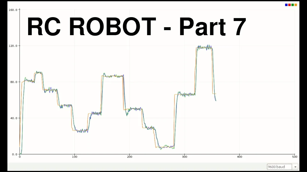
PID Wheel Control and Single Joystick Steering - RC Robot #7
1.3K
This video demonstrates how to implement closed-loop wheel control in an RC robot using PID controllers with incremental encoders for feedback, and how to achieve single joystick steering for differential drive robots by calculating appropriate wheel speeds based on joystick inputs; the presenter explains that PID tuning requires trial and error to find optimal gain settings and sampling frequencies, and that single joystick control simplifies operation while maintaining good straight-line tracking, though mechanical issues like loose components can affect performance.
Click to watch →
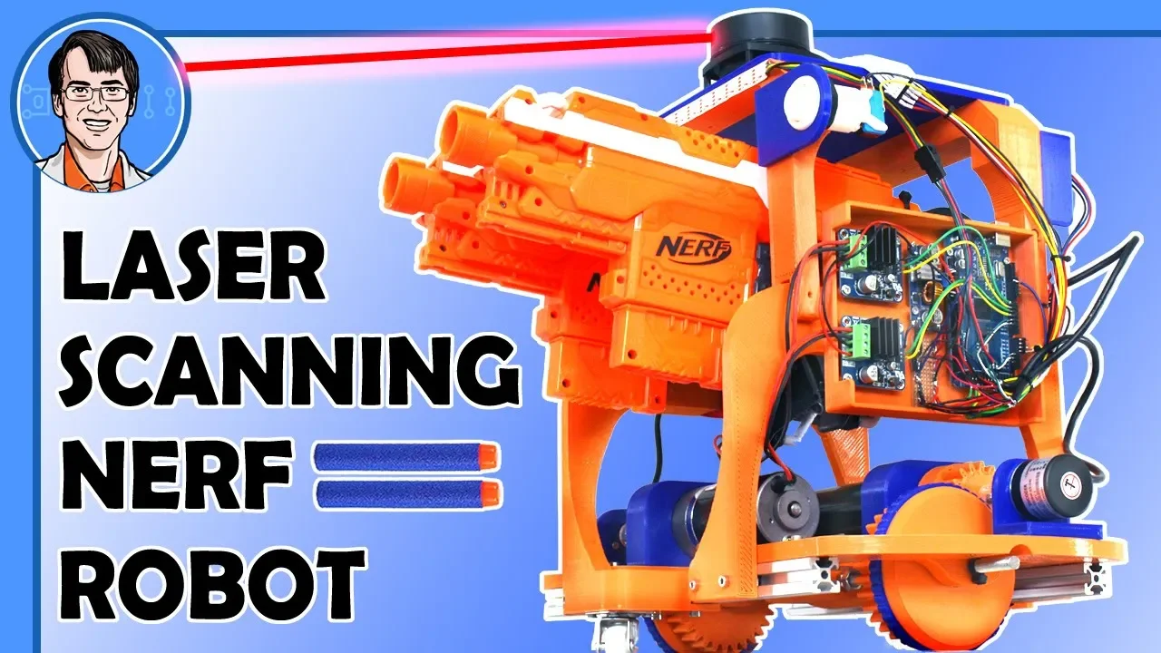
Autonomous NERF Robot controlled by LIDAR
187.4K
Wheel encoders measure rotational position by detecting pulses generated as encoder wheels pass through optical sensors. Quadrature encoders provide directional information by analyzing which sensor triggers first. Encoder counts per revolution determine resolution (e.g., 600 counts per revolution). PID controllers use encoder feedback to achieve precise motor positioning by comparing desired positions against actual encoder readings and adjusting motor speeds accordingly. This closed-loop control system enables accurate rotation and translation of the robot platform despite mechanical imperfections and minor wheel slippage.
Click to watch →

The Ultimate Guide to using Motors in Robotics (including ROS, Raspberry Pi)
483.9K
Implementing closed loop control requires encoder integration and empirical calibration. Encoders use hall effect sensors that generate pulses as a magnetic disk rotates. By counting pulses and dividing by rotation count, we determine counts per revolution (e.g., 3,450 counts/rev). The controller uses PID algorithms to compare actual vs target speeds, adjusting PWM outputs accordingly. Commands like 'm' followed by target counts per loop enable closed loop operation. This demonstrates transforming theoretical feedback control concepts into working hardware implementations.
Click to watch →
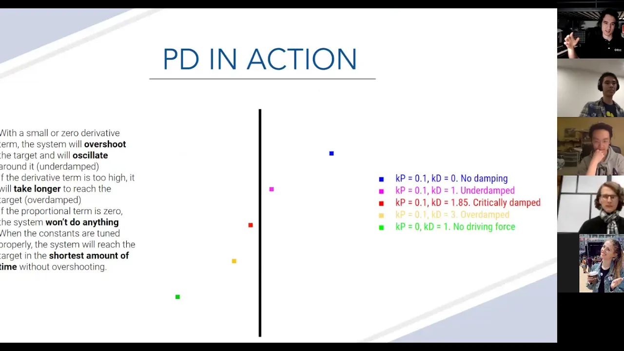
MM 2020-2021 Lecture 3: PID Control
423
PID controllers can be used for both straight-line movement and turning. For straight movement, the error is the difference between desired and actual position (encoder counts). For turning, the error is the difference in encoder counts between left and right motors, which corresponds to how far the robot has turned. The PID output is applied by adding the correction to one motor and subtracting it from the other. This allows the robot to simultaneously control both position and orientation.
Click to watch →

Mark 01 - Differential Robot #4 : Odometry and PID Controller
45.1K
This video demonstrates how to implement wheel encoder-based odometry for robot localization and a PID controller for autonomous navigation. The odometry system estimates the robot's position (x, y, and orientation) by reading wheel encoder ticks and calculating distance traveled, though errors accumulate over time. The PID controller uses this estimated pose to drive the robot toward a goal location by calculating angular velocity targets. Successful implementation requires calibrating the wheel radius and wheelbase parameters using empirical measurements, and tuning the PID gains (P, I, D) through iterative testing. The complete system integrates these components within a state machine architecture that switches between manual joystick control and autonomous GoToGoal mode.
Click to watch →
Deep Dive
Integrating autonomous navigation systems using sensors like LiDAR, ultrasonic sensors, and IMUs (Inertial Measurement Units).

Using a Lidar for Robot Navigation in a Room - Michael E Anderson, The PTR Group, Inc.
35.5K
Effective indoor robot navigation combines LiDAR distance measurements with inertial measurement unit (IMU) data through sensor fusion. The IMU provides nine degrees of freedom (gyroscope, compass, magnetometer, accelerometer) enabling position tracking. SLAM (Simultaneous Localization and Mapping) algorithms integrate these complementary sensor streams to build environmental maps while determining robot location—a self-calibrating approach solving the chicken-and-egg problem of needing both map and localization. Point clouds generated by pan-tilt scanning mechanisms create 3D environmental representations visualizable through software tools like Blender, Processing, Python, and MATLAB.
Click to watch →

Inertial and Imaging Sensor Fusion for an Autonomous Tomorrow
200
Autonomous vehicles achieve reliable navigation through sensor fusion, combining inertial measurement units (IMUs) with visual odometry and wheel speed sensors to overcome individual sensor limitations; IMUs provide low-latency (<4ms) position updates with minimal drift, while cameras offer accurate long-term orientation estimates, and wheel speed sensors provide robust velocity information at high speeds, together achieving sub-meter accuracy even during GPS outages.
Click to watch →

Everything You’re Unsure About the M Series — Ask Ken Live
343
LiDAR (Light Detection and Ranging) is a depth sensing technology that enables navigation in challenging environments where GPS signals are obstructed. The M20i model includes LiDAR, which works by emitting laser pulses and measuring return times to create 3D maps of surroundings. This technology is particularly valuable in areas with dense tree cover where RTK signals struggle. The system fuses LiDAR data with camera data, IMU (Inertial Measurement Unit), and odometry for robust navigation. For small yards under 0.2 acres, LiDAR alone can navigate the entire area without RTK. For larger yards, RTK provides ground truth positioning while LiDAR handles challenging terrain. The system also enables night navigation when cameras cannot see 100 feet ahead.
Click to watch →
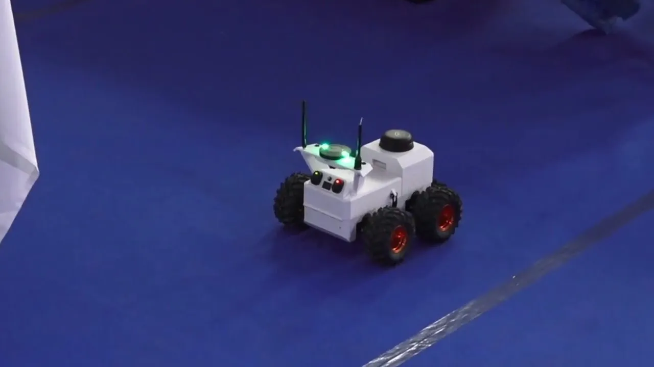
Stephen Dade : ArduRover & ROS2 Autonomy Demo
694
This video demonstrates how to integrate ArduRover with ROS2 for autonomous navigation by fusing LIDAR scan data with IMU and wheel encoder odometry using Cartographer for SLAM mapping and Nav2 for path planning, highlighting the challenges of coordinate frame synchronization and real-time sensor data processing on embedded hardware.
Click to watch →

Geodnet - Robots, Drones & AVs
418
No single sensor can solve all positioning and navigation problems. Camera systems fail in direct sunlight, while other sensors have their own limitations. LIDAR costs are decreasing faster than Moore's Law, with improvements of 10x in capability per year while costs decrease. For autonomous vehicles, safety is paramount and requires sensor fusion combining multiple technologies (camera, LIDAR, radar). Radar is particularly valuable because antenna development is relatively inexpensive and sophisticated signal processing chips are being developed. The safety bar for fully autonomous vehicles will be at least 10x stronger than human drivers, making comprehensive sensor fusion essential for achieving broad market acceptance.
Click to watch →
Deep Dive
Transitioning to the Robot Operating System (ROS) for advanced path planning, mapping, and localization.

ROS NAVIGATION IN 5 DAYS #2 - Mapping & Create a map from zero
69.8K
In ROS navigation, mapping is the process of creating a 2D occupancy grid map of an unknown environment using SLAM (Simultaneous Localization and Mapping), which simultaneously builds the map while localizing the robot within it; this is achieved through the gmapping package that subscribes to laser scan data and robot transforms to publish a map topic containing metadata and occupancy grid information, which can be visualized in RViz and saved as .pgm and .yaml files for use in localization and path planning tasks.
Click to watch →
ROS NAVIGATION IN 5 DAYS #1 - Course Overview & Basics Concepts
100.5K
Autonomous robot navigation in ROS requires three fundamental processes working together. First, a map of the environment must be created by moving the robot around while collecting sensor data, typically using laser scanners. Second, the robot must localize itself within this map, determining its precise position and orientation. This localization uses particle filters that maintain multiple hypotheses about possible robot positions, eliminating inconsistent hypotheses as the robot moves and gathers more sensor information. Third, once localized, the robot can receive goal positions and autonomously navigate toward them. These foundational concepts form the basis for all subsequent navigation capabilities.
Click to watch →

Autonomous Navigation Mobile Robot using ROS | Jetson Nano | RPLidar | Differential Drive Kinematics
162.2K
The ROS navigation stack consists of four main components: (1) Map Server - provides the map data for navigation; (2) AMCL (Adaptive Monte Carlo Localization) - uses sensor data to localize the robot's position within the map; (3) Move Base - generates paths to goal positions while avoiding obstacles using global and local planners, then computes linear and angular velocities; (4) Base Controller - converts these velocities into individual wheel velocity commands. The white components (Map Server, AMCL, Move Base) are pre-implemented in ROS, while blue components (Base Controller, Sensor TF, Odometry Source) are robot platform dependent and require custom implementation.
Click to watch →
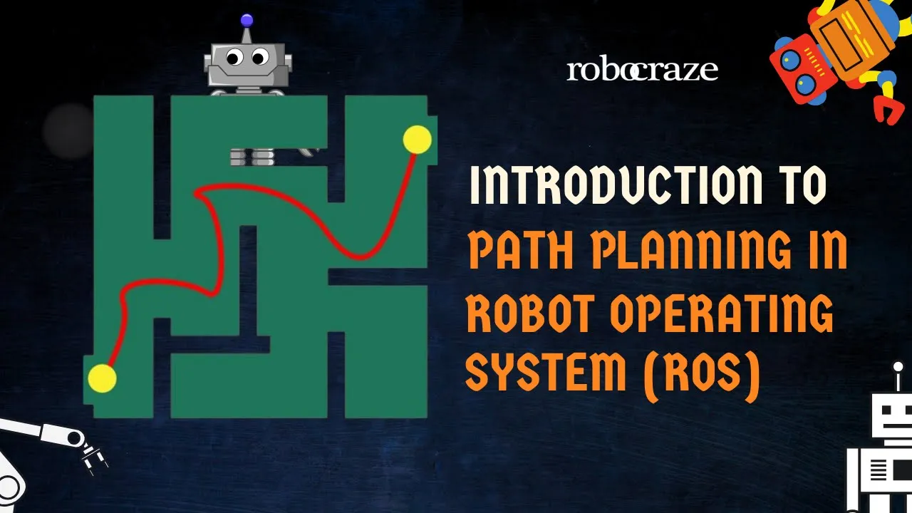
Introduction to Path Planning in Robot Operating System (ROS)
22.3K
This video introduces path planning in robotics using ROS (Robot Operating System) and Gazebo simulation, demonstrating how robots autonomously navigate from starting points to desired locations by identifying optimal routes while avoiding obstacles in both indoor and outdoor environments.
Click to watch →
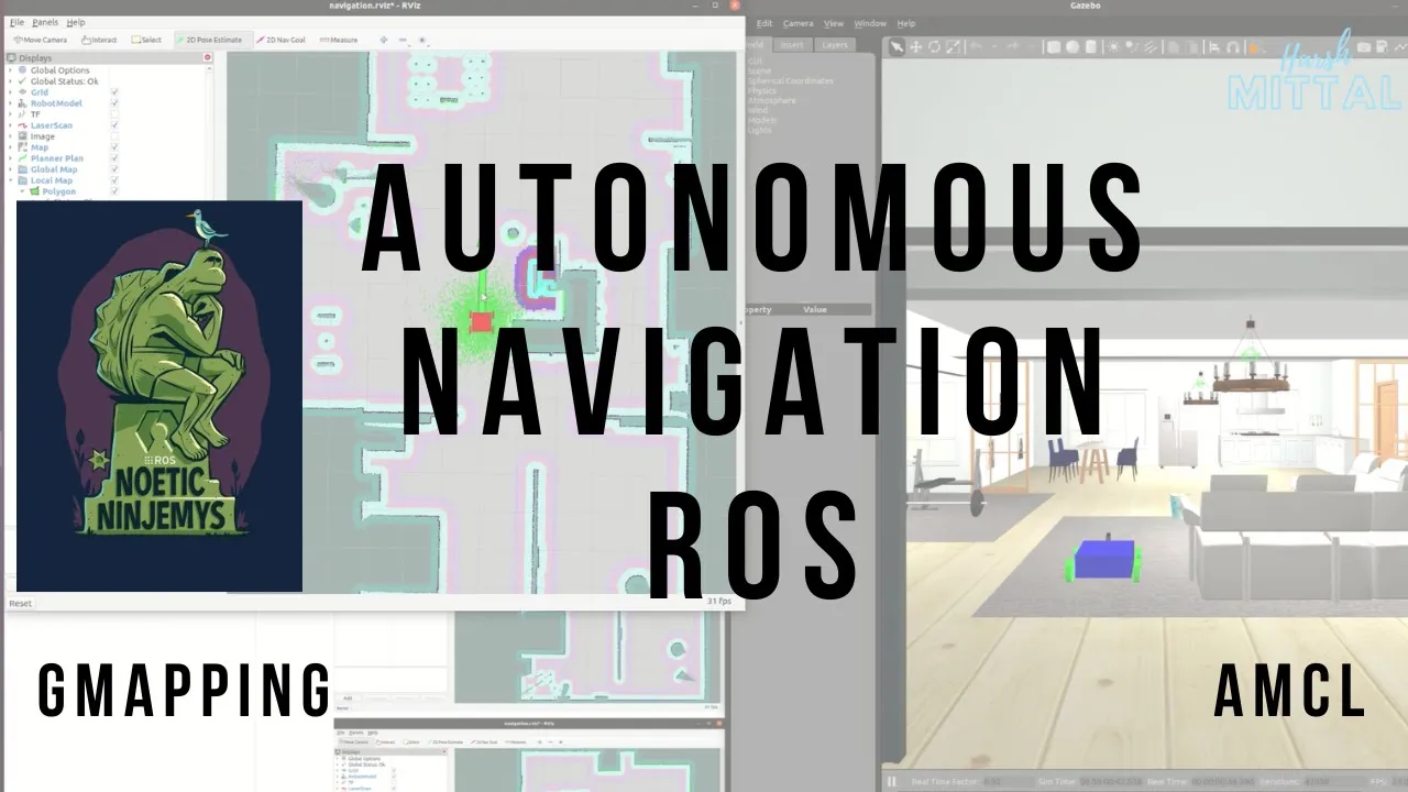
Learn Basics Of Autonomous Navigation for Custom Robot Using ROS | Simple Tutorial | 2022
10K
Autonomous robot navigation in ROS follows a three-stage pipeline: (1) Mapping using GMapping SLAM to create an environment map by scanning with laser sensors while moving the robot, then saving the map as .pgm and .yaml files; (2) Localization using AMCL (Adaptive Monte Carlo Localization) to determine the robot's precise position within the known map by tracking particle distributions that concentrate as the robot moves; (3) Autonomous navigation using move_base to plan paths toward goals while avoiding obstacles through global and local planners, with the robot automatically adjusting its trajectory based on real-time sensor data and costmap information.
Click to watch →
Deep Dive
Studying the mathematical kinematics of the rocker-bogie suspension to analyze how the rover maintains stability over extreme obstacles.

The Jet Propulsion Laboratory W/ Doug Ellison - Part 1
60.8K
Mars rovers use a passive rocker-bogie suspension system with six wheels and four-wheel steering. The suspension includes a differential that links both sides of the rover. This design allows the rover to drive over obstacles up to the size of its own wheels. The system is completely passive, meaning it doesn't require active control to function; the mechanical design naturally distributes weight and absorbs shocks from rough terrain.
Click to watch →

Demo Day 2021 | Yak Rover
213
The rocker bogey suspension system, used in space rovers like Perseverance and Curiosity, provides terrain traversal capability for obstacles twice the wheel height. The system uses rigid parts instead of springs, making it suitable for extreme environments. The differential bar mechanism maintains uniform traction pressure across all wheels by inverting pressure direction on the opposite side when one side encounters an obstacle, similar to how human hips distribute weight during walking. This design allows the rover to climb obstacles while maintaining stability.
Click to watch →

The Engineer who invented the Mars Rover Suspension...in his garage
55.7K
The rocker bogie is a six-wheel articulated suspension system invented by Donald Bickler at NASA's Jet Propulsion Laboratory, which enables planetary rovers to traverse rough terrain by distributing weight evenly across all wheels, maintaining platform stability over obstacles larger than the wheel diameter, and allowing each wheel to maintain independent contact with the ground without scuffing or slipping, making it the preferred mobility solution for all Mars rovers from Sojourner through Perseverance.
Click to watch →
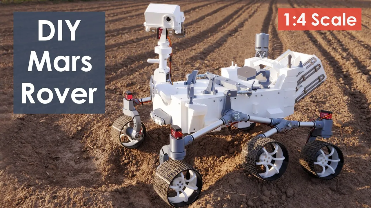
How I Built a Mars Perseverance Rover Replica - Arduino based Project
565.3K
The rocker boogie suspension is a six-wheeled design that allows rovers to traverse uneven terrain smoothly. This system enables the rover to climb obstacles up to twice the wheel diameter while maintaining all six wheels in constant ground contact. Each wheel has an independent DC motor for propulsion, and the four corner wheels feature individual steering servo motors. The Ackermann steering geometry ensures efficient turning by calculating appropriate wheel speeds and angles based on the turning radius, with inner wheels having greater steering angles and slower speeds compared to outer wheels.
Click to watch →

Improved rocker-bogie suspension block - Borri/August - 2021 Mars Society Virtual Convention
3.1K
This video presents an improved rocker-bogie suspension block design that addresses the limitations of traditional Mars rover suspensions by using a block and tackle system with rope or chain passing under the chassis around drums, distributing the rover's weight across six support points instead of two, eliminating the need for differentials or balance bars, enabling skid steering with only two motor channels, and providing inherent redundancy and field-repairability while maintaining the ability to climb obstacles taller than the wheel diameter.
Click to watch →
Deep Dive
Upgrading the communications interface to long-range RF links or Wi-Fi control with video telemetry for true remote exploration.
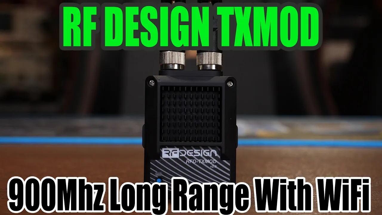
RF Design TXMOD 868/900Mhz Long Range Ground Radio With Wifi
10.1K
RF Designs produces long-range telemetry radios for PX4 and MAVLink-based autopilots, offering two-way communication exceeding 40 kilometers. The TX Mod is a JR-bay compatible module featuring internal RFD radios for 868/900MHz operation, built-in Wi-Fi for wireless data sharing, and waterproof design. Key specifications include 5-18V input range, 52x66x38mm dimensions, and dual antenna diversity. The system enables consolidated wireless control and telemetry transmission, eliminating separate cable runs for control links.
Click to watch →
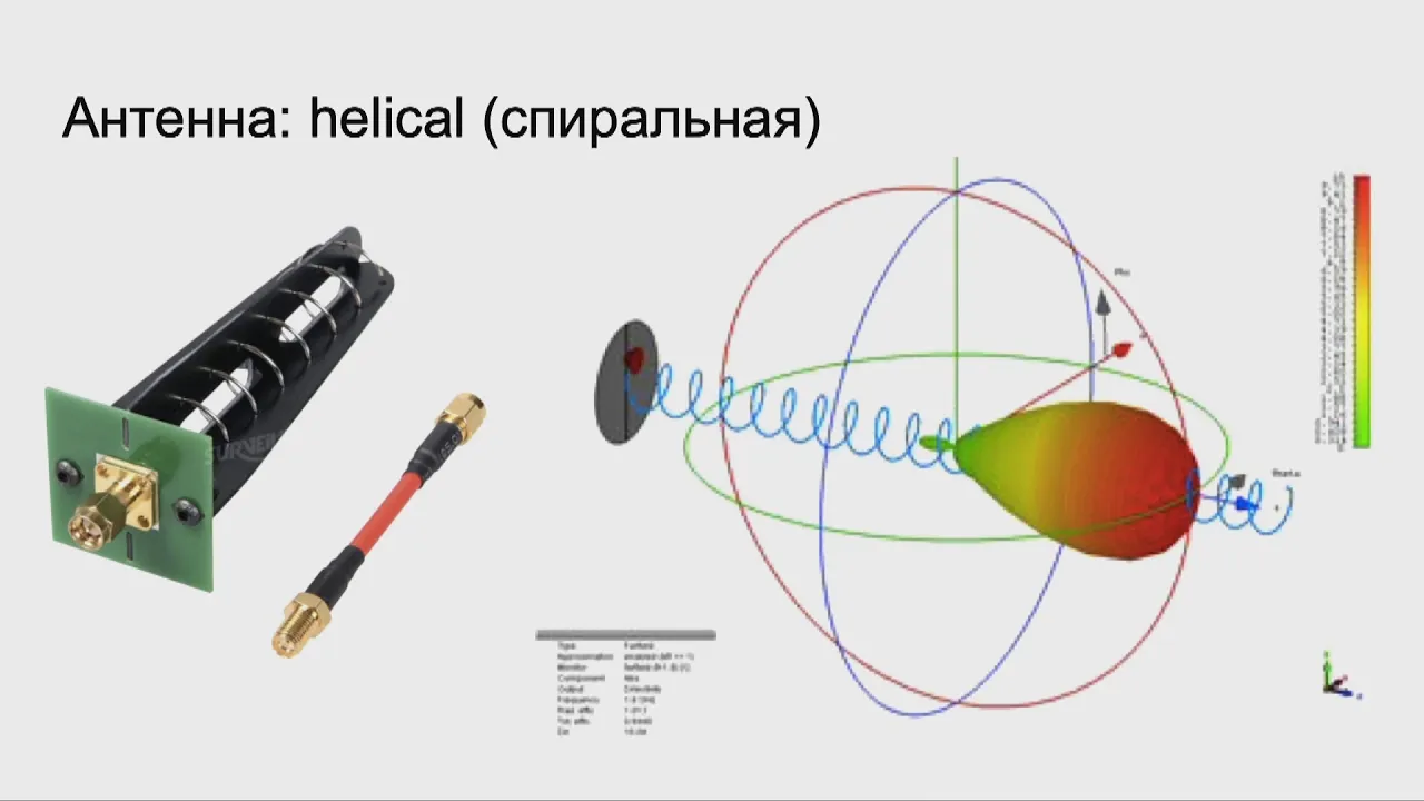
Дальняя связь для самодельных беспилотников: теория и практика. Юрий Лилеков. Митап 12.03.20
69K
Long-range drone communication enables remote control of drones flying far from operators, supporting autonomous missions and telemetry monitoring. Radio control systems operate on different frequencies: 2.4/4.0 GHz for consumer systems, 768/915 MHz for longer-range applications, and 433 MHz for DIY systems. Critical requirements include minimal latency (10-20ms) for radio control to enable quick obstacle avoidance, while telemetry can tolerate higher latency (1-2 seconds). Video signals are transmitted as analog signals to minimize latency, with quality comparable to 1990s VHS at long ranges.
Click to watch →
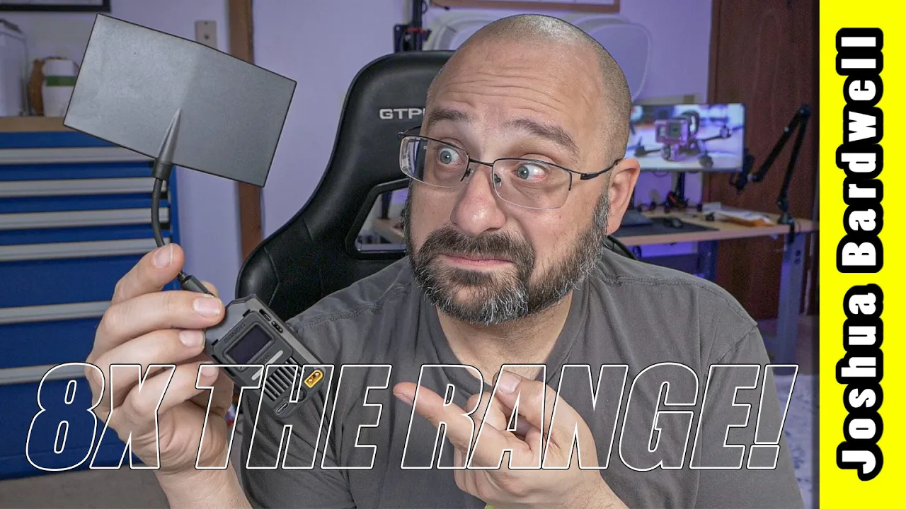
RadioMaster Bandit: 8x the range of 2.4 GHz, but at what cost?
72.8K
In typical long-range systems, the control link operates at full power (1 watt) while telemetry transmits at much lower power (100 mW or less), creating an asymmetrical link where telemetry drops out before control does. By flashing modules to operate as receivers with 1-watt output, both links become symmetrical - maintaining telemetry as long as possible. This is critical for autonomous drones relying solely on telemetry for ground control communication.
Click to watch →

Wifi telemetry
3.5K
Telemetry enables two-way communication between drones and ground control stations, transmitting GPS position, throttle settings, orientation, and temperature. MAVLink is the serial protocol enabling this communication, sending packets (8-263 bytes) at ~10 Hz with key messages including heartbeat (1 Hz) and GPS data (10 Hz). The system architecture uses an ESP32 microcontroller with onboard Wi-Fi to replace USB cable communication. The flight controller connects to the ESP32 via UART, and the ESP32 translates MAVLink data to Wi-Fi for wireless communication with ground control stations.
Click to watch →

RADIO FREQUENCY TELEMETRY SYSTEM RF TELEMETRY systems SENSORS AND TRANSDUCERS|VTU|KTU|ECE|EEE|EIE|AE
2.1K
RF telemetry systems enable wireless transmission of sensor data over distances exceeding one kilometer without physical connections, utilizing microwave frequencies (300 MHz to 300 GHz) with wavelengths from 1 meter to 1 millimeter; the system comprises a sending end with sensors/transducers, signal conditioning, modulators, and transmitting antennas, and a receiving end with receiving antennas, amplifiers, demodulators, and end devices (storage or display), where modulation combines the original signal with a carrier wave for transmission and demodulation separates them at the receiving end.
Click to watch →
Rover Demo
Steering Issue
Rover Demo
0:03- 1
Shows rover with rocker-bogie suspension and balanced seat.
- 2
Uses Arduino with motor drivers for main drive control.
Simplifying Educational Robotics: The Case Against Rocker-Bogie Suspension for Beginners
While the rocker-bogie suspension is celebrated for its NASA heritage, it is often overly complex and impractical for introductory educational robotics. For children and beginners learning with Arduino, the design presents several drawbacks. First, it requires at least six motors and intricate mechanical linkages, significantly increasing costs, assembly difficulty, and potential points of mechanical failure. Second, rocker-bogie systems are engineered exclusively for extremely slow, deliberate movement; higher speeds cause severe instability, making the vehicle less engaging for kids who prefer responsive, fast RC toys. Finally, managing six motors and complex steering geometry adds a steep programming curve that can overwhelm novice learners. Critics argue that simpler alternatives, such as four-wheel-drive (4WD) differential chassis or tracked systems, offer a more accessible, robust, and cost-effective introduction to mobile robotics, allowing students to focus on fundamental coding and sensor integration rather than troubleshooting complex mechanical linkages.
Basic Arduino programming, including uploading sketches, using the Arduino IDE, and understanding digital and analog I/O pins.
Fundamental electronics concepts such as voltage, current, power sourcing, and the function of an H-bridge motor driver.
The physical concepts of center of mass, torque, and basic mechanical leverage, which govern how vehicle suspensions balance.
Familiarity with basic hand tools and prototyping materials for physical chassis assembly.
Implementation of closed-loop control systems, such as PID controllers, using wheel encoders to ensure straight-line tracking and precise steering.
Integrating autonomous navigation systems using sensors like LiDAR, ultrasonic sensors, and IMUs (Inertial Measurement Units).
Transitioning to the Robot Operating System (ROS) for advanced path planning, mapping, and localization.
Studying the mathematical kinematics of the rocker-bogie suspension to analyze how the rover maintains stability over extreme obstacles.
Upgrading the communications interface to long-range RF links or Wi-Fi control with video telemetry for true remote exploration.
151.3K views5.9Klikes2:51@KrisTemmermanNPOriginal Release: 2019-04-01
[Music] hi guys I'm back with a short demo video and really happy how this project turned out especially the rocker-bogie suspension all the joints can move freely and the seat is kept up straight and balanced thanks to the differential bar that connects the two top rockers the result is that all the will stay nice on the ground even on rough terrain right now I use a remote control to drive it but when my son is a little bit older you can use the joystick in front the brain of the Hoover is an Arduino to it and the main C motors are driven by beefy 60 M motor drivers they have plenty of power and seem to manage everything I drove at in contrast the stepper motors for turning the wheels are a little bit underpowered I think if I created drivers I can get better results putting the heavy encoders so I can manage lost steps anyway my son loves his new form of Transportation and I guess that's the important part I just built a Rover as I went so I don't have any plans but I will put a part list in a link to the source code in the description and if you haven't seen the build video make sure to check it out thanks for watching and I'll see you next time
Up Next

10:48
Racecar Engineering: Chassis Design Principles for Rigidity
@mechanicaldesign101
106.9K views•2017-07-24

30:32
Ultrasonic Transducers: Resonant Frequency Measurement and Horn Design
@imajeenyus42
229.9K views•2017-02-22
4:08
Converting a Stepper Motor to Closed-Loop with Encoder
@KrisTemmermanNP
345.7K views•2015-01-16

33:39
How a Student's Question Saved a NYC Skyscraper from Collapse
@veritasium
22.8M views•2025-04-26
Related Study Plans & Knowledge Roadmaps
Structured learning paths in Engineering
engineering
Building Acoustic Levitators: Physics & Arduino
01The Physics of Sound and Standing Waves
02Piezoelectric Transducers and H-Bridge Drivers
03Arduino Programming: Generating 40 kHz Signals
+ 2 more learning modules
14h5 modules
Explore Roadmap
engineering
Building Peltier Cloud Chambers: Particle Tracks
01Cosmic Rays & Cloud Chamber Physics
02Thermoelectric Cooling (TEC) Fundamentals
03Custom Liquid-Cooling Loop Design
+ 2 more learning modules
18h5 modules
Explore Roadmap
engineering
Yagi-Uda Antennas: Modeling, Build & VNA Test
01Introduction to RF and Antenna Fundamentals
02Yagi-Uda Antenna Design Principles
03Antenna Modeling and Simulation in 4NEC2
+ 2 more learning modules
18h5 modules
Explore Roadmap
engineering
ECG Monitor Design: Op-Amps, Filters & Noise
01Electronics & Breadboard Basics
02Op-Amps and Instrumentation Amplifiers
03Bioelectricity and ECG Fundamentals
+ 2 more learning modules
18h5 modules
Explore Roadmap