Soft Robotics: Molding, Arduino & Closed-Loop Control
Learning Goal: Design, mold, and test a pneumatic soft robotic gripper using silicone elastomer, implementing a closed-loop pressure control system with an Arduino and solenoid valves to safely grasp delicate objects.
- Prerequisites: Basic understanding of algebra and general physics concepts. No prior programming or molding experience is required.
- Estimated Total Study Time: 25 Hours
Module 1: Introduction to Soft Robotics & Pneumatic Actuation
This module introduces the interdisciplinary field of soft robotics. You will explore how compliant, bio-inspired materials differ from traditional rigid systems, learn the fundamental physics of fluidic elastomer actuators (specifically Pneunets), and examine real-world applications in handling delicate objects.
Recommended Videos

Why this video is valuable: This short introductory video visually bridges the gap between biological systems (like octopi) and mechanical engineering. It introduces the core philosophy of "compliance" in robotics, showing how flexible rubber polymers and structures adapt to complex geometries in ways traditional rigid robots cannot.

Why this video is valuable: The Harvard Soft Robotics Toolkit is the premier open-source repository for soft actuator design. This video gives a high-level overview of their resources, including step-by-step fabrication files, modeling tutorials, and control strategies. It serves as your main reference guide for the physical designs you will fabricate later in this course.

Why this video is valuable: Demonstrates how multiple collaborative soft actuators can mimic natural forms (such as jellyfish tentacles) to wrap around and grip highly delicate, irregular objects without causing structural damage. This provides direct inspiration for the grasping tasks you will conduct in Module 5.
💡 Supplement: Actuator Bending Physics & Independent Study
While these high-level overviews demonstrate soft robotic capabilities, they do not illustrate the exact internal chamber expansion physics of Pneunet bending actuators.
How a Pneunet (Pneumatic Network) Actuator Works: A Pneunet actuator consists of two primary layers:
- The Expandable Chambers (Top Layer): Molded from a soft, stretchable silicone elastomer (low durometer, e.g., Ecoflex).
- The Strain-Limiting Layer (Bottom Layer): Reinforced with an unstretchable material (such as paper, fabric, or a high-durometer, stiff silicone like Dragon Skin).
When air is pumped into the internal chambers, the pressure forces the thin walls of the top chambers to expand outward. Because the bottom layer is constrained by the strain-limiting material, it cannot stretch longitudinally. This asymmetry in material strain forces the entire actuator to bend toward the strain-limiting side.
   UNPRESSURIZED                       PRESSURIZED (Bending)
 _________________                      _____      _____
[ | | | | | | | | ] Chambers           (     )____(     )  <-- Expandable
=================== Strain-Limiter      \==============/   <-- Restrained
- Independent Search Recommendation: To visualize this expansion in real-time, search YouTube for:
"Pneunet bending actuator working principle animation"or"Harvard soft robotics toolkit pneumatic gripper simulation".
Knowledge Checkpoint
- Explain the difference between "structural compliance" and "rigid joint actuation."
- Identify the two layers required to make a soft actuator bend instead of inflating like a balloon.
- Define what a "strain-limiting layer" is and name two materials commonly used to create it.
- Describe why soft actuators are inherently safer for handling fragile structures compared to metal parallel grippers.
Module 2: Arduino Programming and Electronics Foundations
To build an automated, closed-loop pressure system, you must first master the electronic control framework. This module covers the basics of Arduino microcontrollers, safe breadboard prototyping, and using NPN transistors and N-channel MOSFETs to switch higher-power devices (like 12V air pumps and solenoids) from 5V digital pins.
Recommended Videos

Why this video is valuable:
An absolute beginner-friendly guide to setting up the Arduino IDE. You will learn about the standard code structure—namely void setup() and void loop()—along with basic programming concepts in the simplified C++ environment.
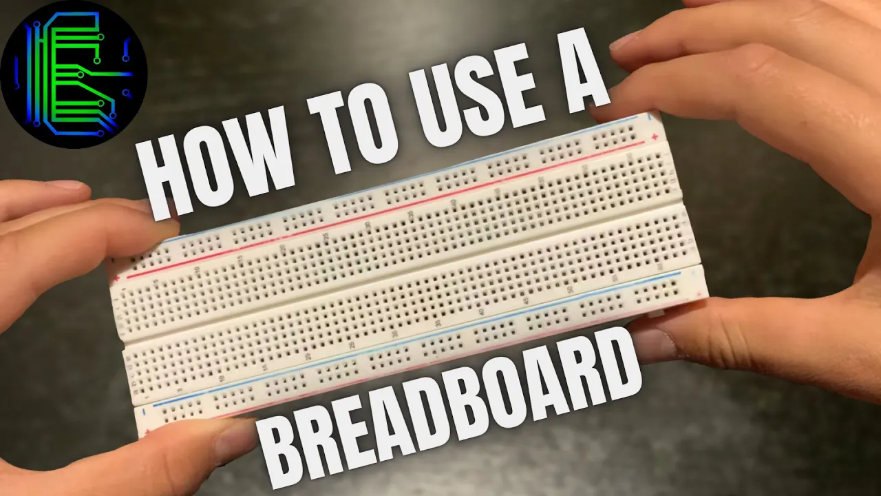
Why this video is valuable: Explains the internal physical connections of a standard breadboard. Knowing how the power rails and terminal strips are linked is essential for safely building circuits and avoiding short circuits during your build.
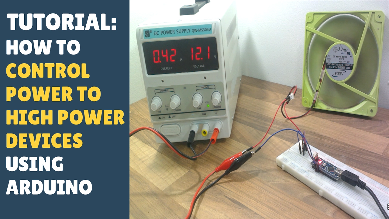
Why this video is valuable: Arduino digital output pins are limited to 5V and around 20-40mA of current, which is too low to drive the 12V pumps and solenoid valves used in soft robotics. This video explains how to use an NPN transistor (or N-Channel MOSFET) as an electronic switch to safely control high-power loads using a low-power Arduino pin.
Knowledge Checkpoint
- Draw a diagram showing how breadboard terminal strips are electrically connected relative to the power rails.
- Write a simple Arduino sketch that reads an analog input pin and prints the raw 10-bit integer value (0–1023) to the Serial Monitor.
- Identify the three main pins of a transistor/MOSFET (Gate/Base, Drain/Collector, Source/Emitter) and explain their function in switching a 12V load.
- Explain why a flyback diode is necessary when switching inductive loads like solenoid valves and motors.
Module 3: Silicone Elastomer Molding and Fabrication
Note: Following the revised curriculum sequence, this module has been moved ahead of pneumatic circuit design. Silicone elastomers require between 4 and 24 hours to fully cure at room temperature. By fabricating and casting your soft fingers now, you can leave them to cure while you study circuit design and sensor integration in Module 4.
Recommended Videos

Why this video is valuable: A highly detailed, professional visual guide to molding a high-durability soft bending finger (the PneuFlex). It demonstrates mold-release preparation, two-step silicone casting, inserting a textile strain-limiting layer, and assembling the final airtight structure.

Why this video is valuable: This tutorial is customized for academic settings, using widely available EcoFlex silicone. It shows the step-by-step process of mixing Part A and Part B in a 1:1 ratio, pouring the mixture into a 3D-printed mold, and demolding the finished components safely.
Why this video is valuable: Trapped air bubbles are the primary cause of mechanical failure in silicone actuators, as bubbles create weak spots that rupture under pressure. This video visually explains how a vacuum degassing chamber works to expand and pop trapped air bubbles, ensuring clean, strong, and air-tight casts.
Knowledge Checkpoint
- Describe the mixing ratio of EcoFlex (e.g., EcoFlex 00-30 or 00-50) and explain why precise, slow mixing is critical.
- Explain how a vacuum chamber removes microscopic air bubbles from viscous silicone mixtures.
- Outline the process for bonding the strain-limiting bottom layer to the chambered top layer without clogging the internal air pathways.
- Identify two signs of under-cured silicone and name two factors (such as cold temperatures or sulfur contamination) that can inhibit curing.
Module 4: Pneumatic Circuit Design and Solenoid Control
In this module, you will design the physical pneumatic system that controls the airflow. You will build a hardware circuit that interfaces an Arduino with a 12V mini air pump, electronic solenoid valves (to direct inflation, holding, and venting), and an analog electronic pressure sensor to read system pressure in real-time.
Recommended Videos
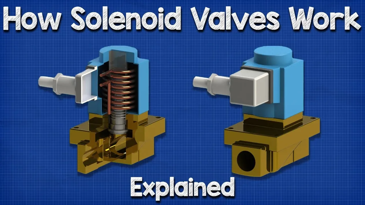
Why this video is valuable: Provides a clear, animated explanation of the internal mechanics of a solenoid valve. You will learn how an electromagnetic coil moves an internal plunger to block or allow fluid flow, helping you understand how to use these valves to seal or release air pressure.
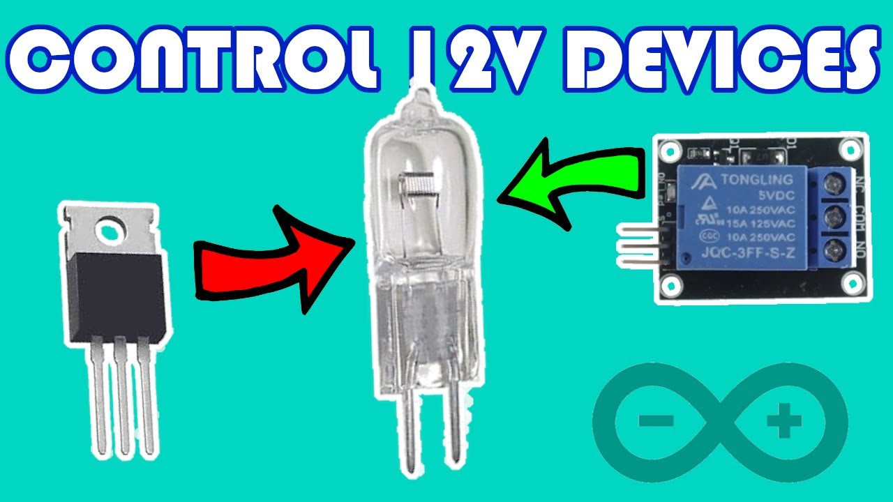
Why this video is valuable: Compares using relays versus N-Channel MOSFETs to control 12V devices. Since pressure-regulation systems require fast, continuous switching (such as Pulse Width Modulation), this video explains why solid-state MOSFETs are a better choice than slow mechanical relays.
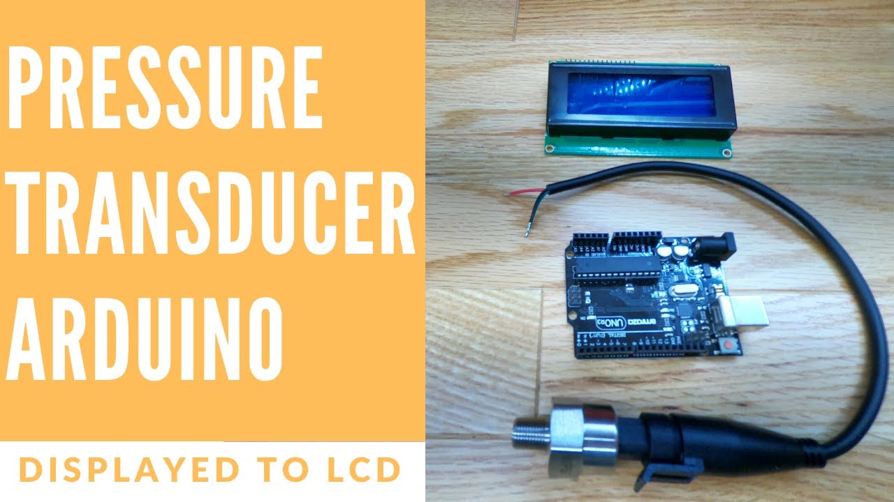
Why this video is valuable: A complete walkthrough showing how to interface an analog pressure transducer with an Arduino. You will learn how to read the analog output voltage and mathematically scale it to standard units of pressure (such as PSI or kPa) in your code.
🛠️ Pneumatic Circuit Schematic
To control your gripper, assemble your hardware according to this schematic:
        +12V DC Power Supply
             |
             +---------------+---------------+
             |               |               |
         [12V Pump]    [12V Solenoid]  [Pressure Sensor VCC]
             |               |               |
             + (Flyback      + (Flyback      |
             |  Diodes)      |  Diodes)      |
             |               |               |
          (Drain)         (Drain)            |
         [MOSFET 1]      [MOSFET 2]          |
          (Source)        (Source)           |
             |               |               |
 GND --------+---------------+---------------+ (GND Sensor)
  |          |               |               |
  |          |               |               |
[ | | | | ] [ Arduino D5(Gate)---------->| | ] [ D6(Gate)-------------------------->| ] [ A0 (Analog Input)<-----------------+ (Sensor Output Signal) ]
Knowledge Checkpoint
- Explain the difference between a 2-way/2-position (normally closed) solenoid valve and a 3-way/2-position valve in a pneumatic circuit.
- Write a line of C++ code to scale a raw 10-bit analog read (0-1023) from a 0.5V-4.5V pressure sensor (0 to 100 kPa) into an actual pressure float variable in kPa.
- Draw a diagram showing how to connect a flyback diode across a inductive load (pump/valve coil) to prevent transient voltage spikes from damaging your MOSFET.
- Explain why a solid-state MOSFET can handle high-frequency switching, whereas a mechanical relay cannot.
Module 5: Closed-Loop Pressure Control & Grasp Testing
This final module ties your physical silicone actuators, pneumatic hardware, and electronics together. You will implement a feedback loop (using Proportional-Integral-Derivative logic, or a simplified threshold-based hysteresis loop) to inflate your soft gripper to a precise target pressure, holding it steady to safely grasp fragile items without crushing them.
Recommended Videos

Why this video is valuable: Explains how to implement a PID control loop in Arduino. It covers calculating elapsed time (), computing the Proportional, Integral, and Derivative terms from an error signal, and scaling those values to write a corrected control output.
Why this video is valuable: Focuses specifically on building a closed-loop controller using a feedback pressure sensor. This helps bridge the gap between general PID theory and practical pressure-regulation systems.
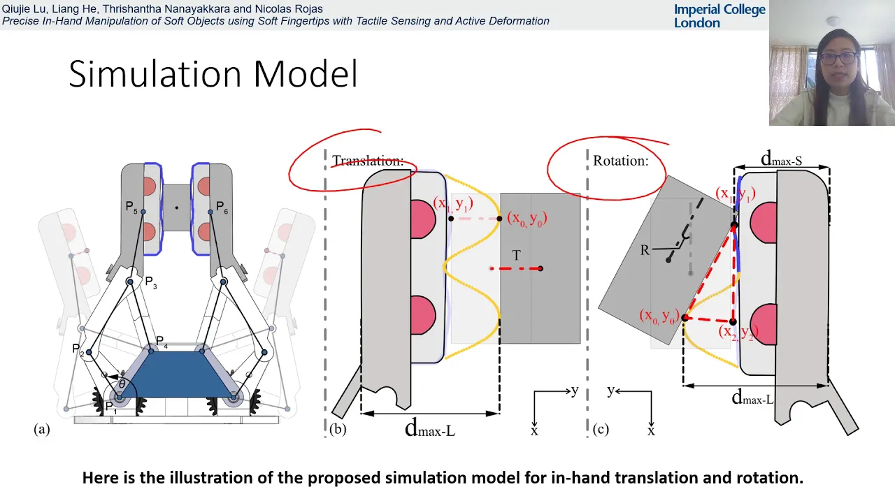
Why this video is valuable: Demonstrates the experimental setup and sensor feedback loops used by researchers to monitor contact forces. This serves as an excellent model for your final testing protocol when evaluating how safely your gripper holds delicate structures.
🎓 Supplement: Gap-Filling Arduino PID Implementation
As noted in the course review, few online tutorials provide complete, ready-to-use code for managing pressure systems using simple solenoid valves. To bridge this gap, write your code using the structured framework below. This example implements a threshold-based hysteresis controller to inflation-limit your system, protecting fragile objects like eggs.
/*
- Arduino Soft Robotics Closed-Loop Pressure Control Framework
- Safely inflation-limits and holds a target pressure within a soft finger. */
const int SENSOR_PIN = A0; // Pressure sensor analog output const int PUMP_PIN = 5; // MOSFET Gate driving the 12V Air Pump const int VALVE_PIN = 6; // MOSFET Gate driving the 12V Vent Solenoid Valve
// Target and safety limits (values in kPa) float targetPressure = 15.0; // Target pressure for secure grasp float safetyPressureLimit = 25.0; // Hard cutoff to prevent actuator rupture float pressureHysteresis = 1.5; // Acceptable deadband around target pressure
void setup() { pinMode(PUMP_PIN, OUTPUT); pinMode(VALVE_PIN, OUTPUT); Serial.begin(9600);
// Safe default: system vented, pump off digitalWrite(PUMP_PIN, LOW); digitalWrite(VALVE_PIN, HIGH); // Assuming normally-closed valve: HIGH opens/vents }
float readPressureKPa() { int rawADC = analogRead(SENSOR_PIN); // Example scaling formula: 0.5V - 4.5V sensor mapped to 0 - 100 kPa float voltage = rawADC * (5.0 / 1023.0); float pressure = (voltage - 0.5) * (100.0 / 4.0); if (pressure < 0) pressure = 0; return pressure; }
void loop() { float currentPressure = readPressureKPa();
// --- Safety Override --- if (currentPressure >= safetyPressureLimit) { digitalWrite(PUMP_PIN, LOW); // Force pump off digitalWrite(VALVE_PIN, HIGH); // Open vent valve immediately Serial.println("!!! OVERPRESSURE SAFETY LIMIT EXCEEDED. VENTING !!!"); while(true); // Lock execution for manual safety reset }
// --- Hysteresis Loop Control --- if (currentPressure < (targetPressure - pressureHysteresis)) { // Under-pressurized: Inflate digitalWrite(VALVE_PIN, LOW); // Close venting valve digitalWrite(PUMP_PIN, HIGH); // Run pump Serial.print("Status: INFLATING... "); } else if (currentPressure > (targetPressure + pressureHysteresis)) { // Over-pressurized but under safety limit: Vent slightly digitalWrite(PUMP_PIN, LOW); // Turn off pump digitalWrite(VALVE_PIN, HIGH); // Open vent valve slightly Serial.print("Status: DEFLATING... "); } else { // Within acceptable target range: Hold pressure digitalWrite(PUMP_PIN, LOW); // Turn off pump digitalWrite(VALVE_PIN, LOW); // Close valve to trap air inside finger Serial.print("Status: HOLDING TARGET... "); }
Serial.print("Pressure (kPa): "); Serial.println(currentPressure); delay(100); // 10Hz control loop cycle }
🥚 Experimental Testing Protocol: Safe Egg Grasping
Once your physical setup and code are ready, use this step-by-step testing protocol to evaluate your system's performance safely:
- Dry-Run Calibration: Connect your cured fingers to the pneumatic circuit without placing any objects in the grip. Run your code with a very low target pressure (e.g., 5 kPa). Verify that your pump runs, the fingers bend inward, the sensor reads the rising pressure, and the pump cuts off when the target is reached.
- Leak Testing: Set the target pressure to 12 kPa. Once reached, observe the system status. If the pump cycles on and off repeatedly while trying to hold pressure, look for tiny air leaks along your tubing connectors or silicone seams using a soapy water solution (which will bubble at leak sites).
- Rigid Target Trial: Position a rigid plastic bottle inside the gripper. Run the system to verify that the fingers conform around the container and hold pressure securely.
- Fragile Target Test (The Egg Trial):
- Use an raw chicken egg as your test object. Mount it securely in a vertical stand.
- Start with a conservative target pressure of 8 kPa. Run the system.
- Observe if the fingers conform to the egg's surface. Try gently lifting the gripper base. If the egg slips, increase the target pressure in 1.5 kPa steps until the grasp is secure.
- Record the minimum holding pressure () that successfully lifts the egg without damage.
- Verify that your software safety limit is set to no more than to prevent accidental crushing.
Knowledge Checkpoint
- Identify the three terms of a PID controller (, , ) and describe how each influences how quickly and stably your system reaches its target pressure.
- Explain what "integral windup" is and how it can cause a pressure system to overshoot and damage a fragile object.
- Describe the purpose of a "hysteresis band" (deadband) in a simple threshold-based valve controller.
- List two methods for physically sealing air connections between stiff vinyl tubing and flexible silicone fingers to prevent system leaks.
Course Map
This flowchart maps the recommended path through the modules. Notice how Module 3 (Silicone Molding) is scheduled before Module 4 (Pneumatics) to allow curing time, helping you make the most of your lab hours.
Key People Index
- Harvard Biodesign Lab Researchers (The Soft Robotics Toolkit Team): An open-source collective that helped standardize soft robotic mold designs and pneumatic control systems, making soft robotics fabrication accessible to students and hobbyists worldwide.
- The RBO Lab Team (TU Berlin): Creators of the highly resilient PneuFlex soft actuator designs. They pioneered techniques for incorporating structural fabric constraints directly into molded silicones.
Final Course Self-Assessment
Complete this checklist to verify that you have mastered all the skills taught in this curriculum:
- Explain the physics behind bending actuators (specifically the relationship between expandable chambers and strain-limiting layers).
- Choose an appropriate silicone elastomer (such as EcoFlex 00-30 or 00-50) based on its durometer, pot life, and cure time.
- Mix, degas in a vacuum chamber, cast, and cure a leak-free multi-chambered silicone actuator finger.
- Wire a safe breadboard circuit that connects an Arduino to high-power 12V pneumatic devices using MOSFETs and flyback diodes.
- Interface an analog pressure transducer with an Arduino, read its output voltages, and mathematically scale them to physical units of pressure.
- Implement an Arduino control loop (such as a hysteresis or PID loop) that dynamically monitors pressure sensor readings and controls air valves.
- Configure code-level safety overrides that dump system pressure immediately if readings exceed safety limits.
- Safely grasp and lift a delicate, raw egg using your closed-loop pneumatic soft robotic gripper system.