
![Jak programować w C? | #15 [Arduino]](https://i.ytimg.com/vi/9BaWincwwTk/maxresdefault.jpg)




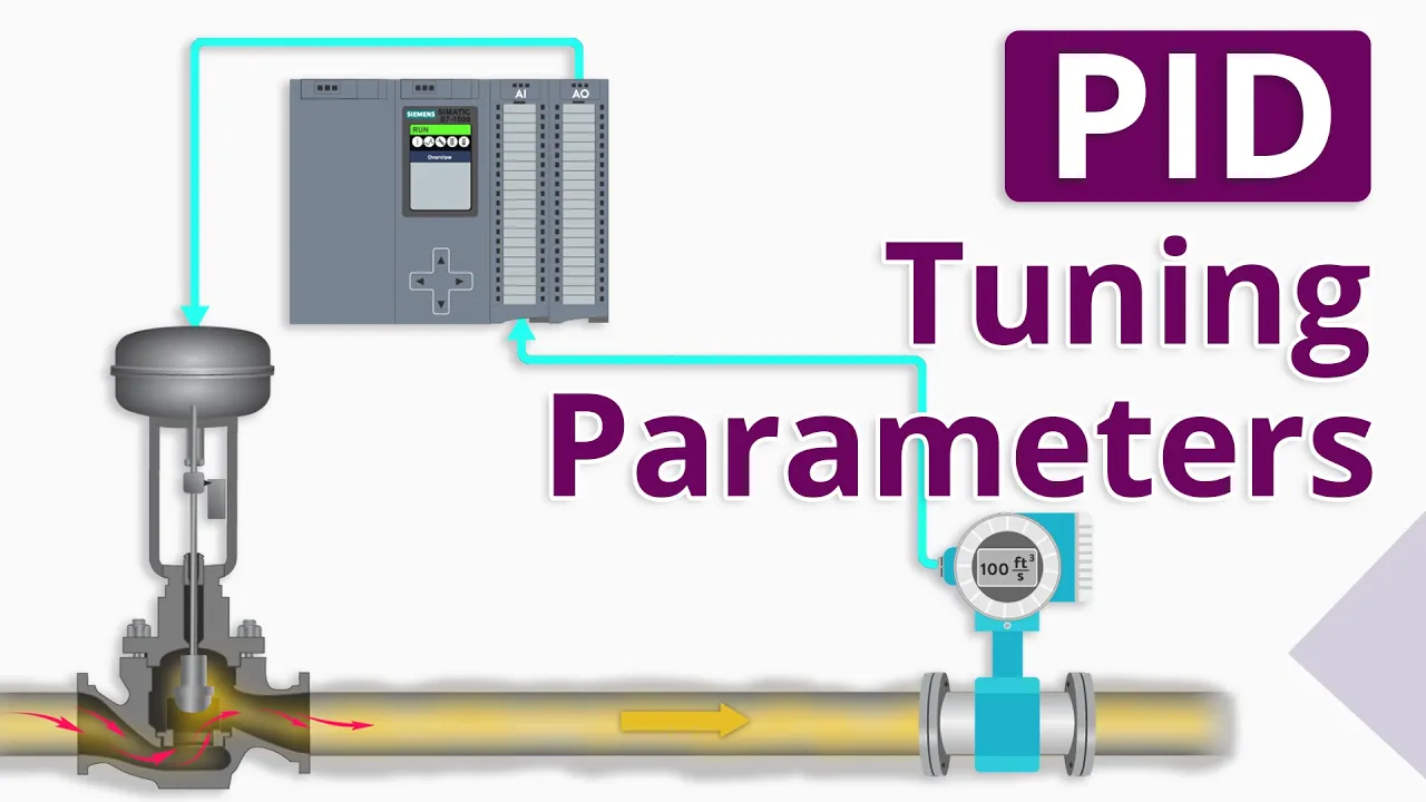
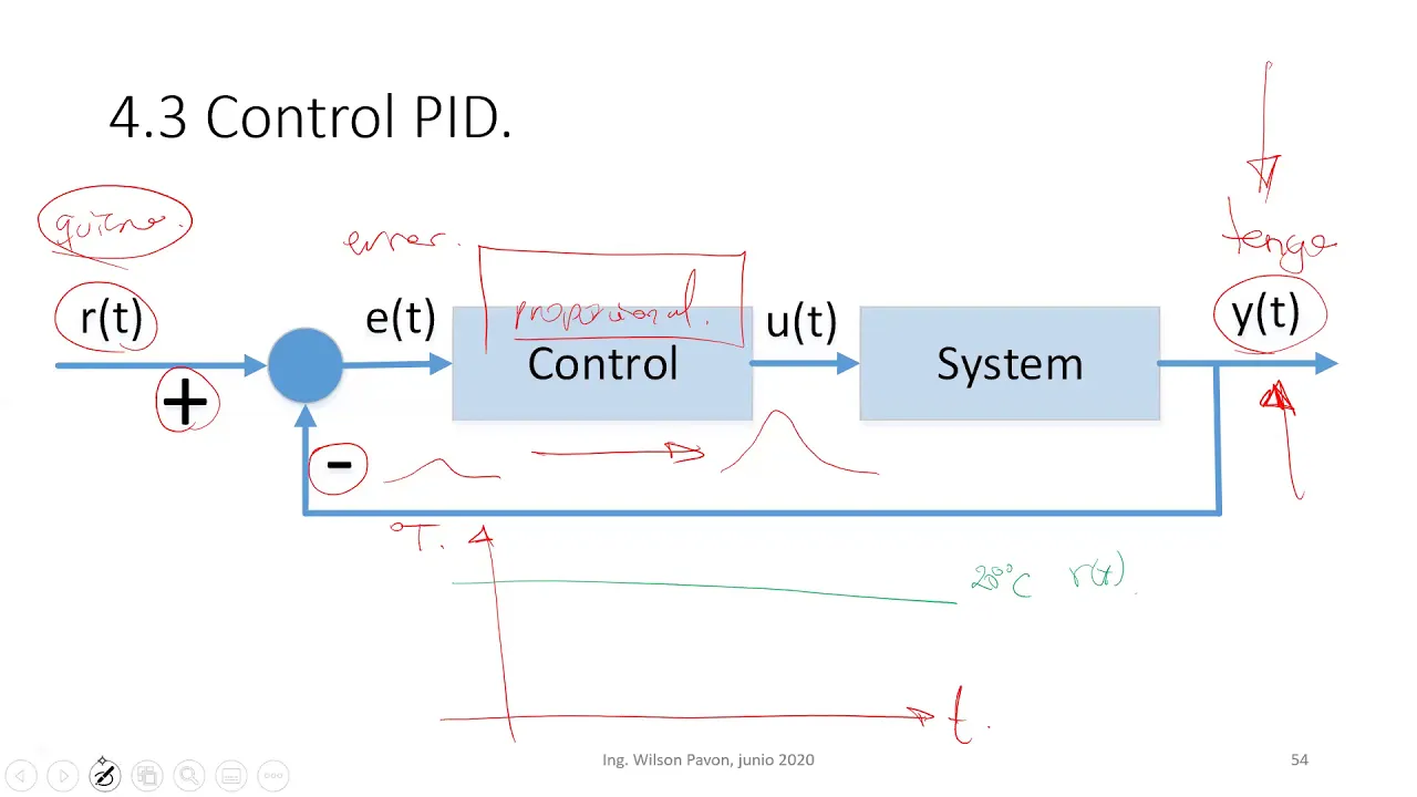


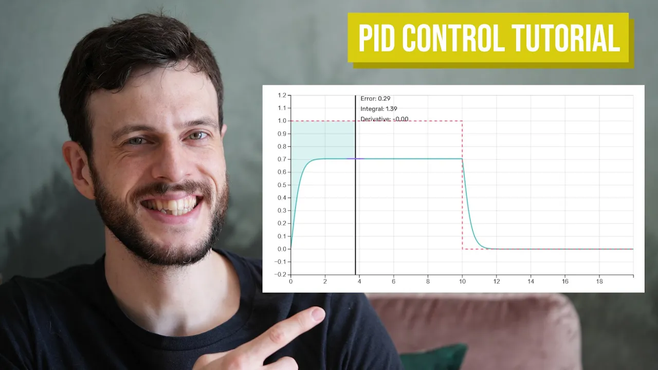



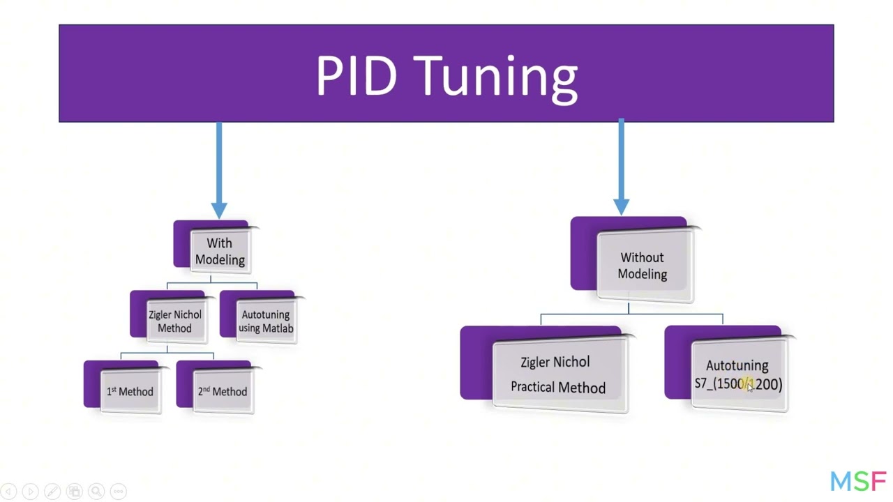
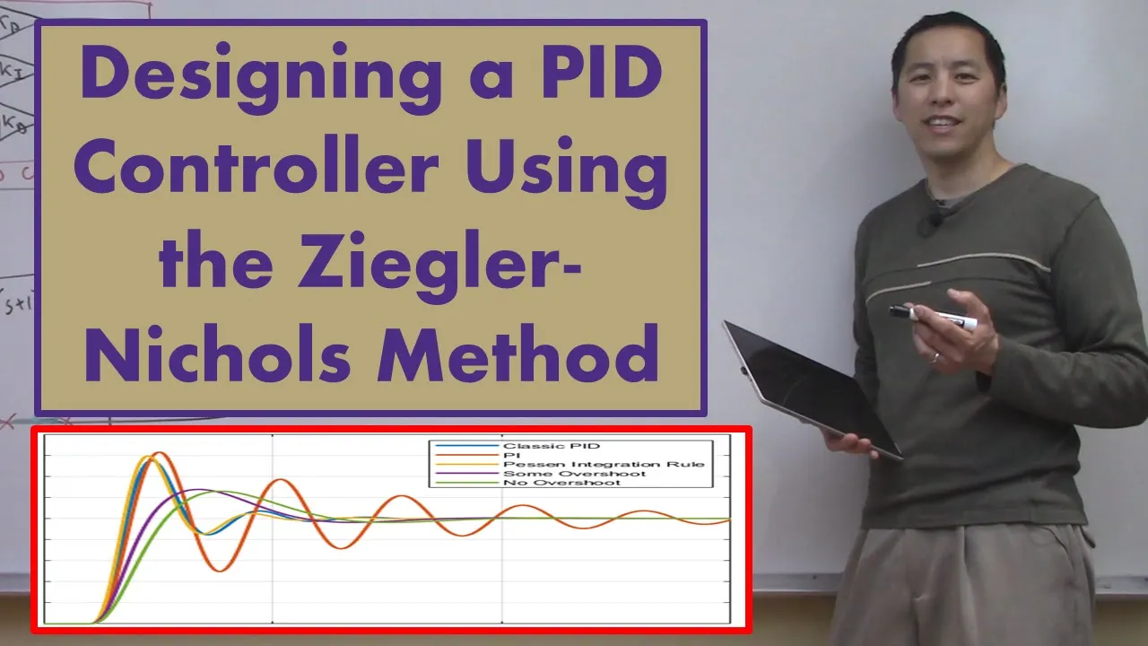



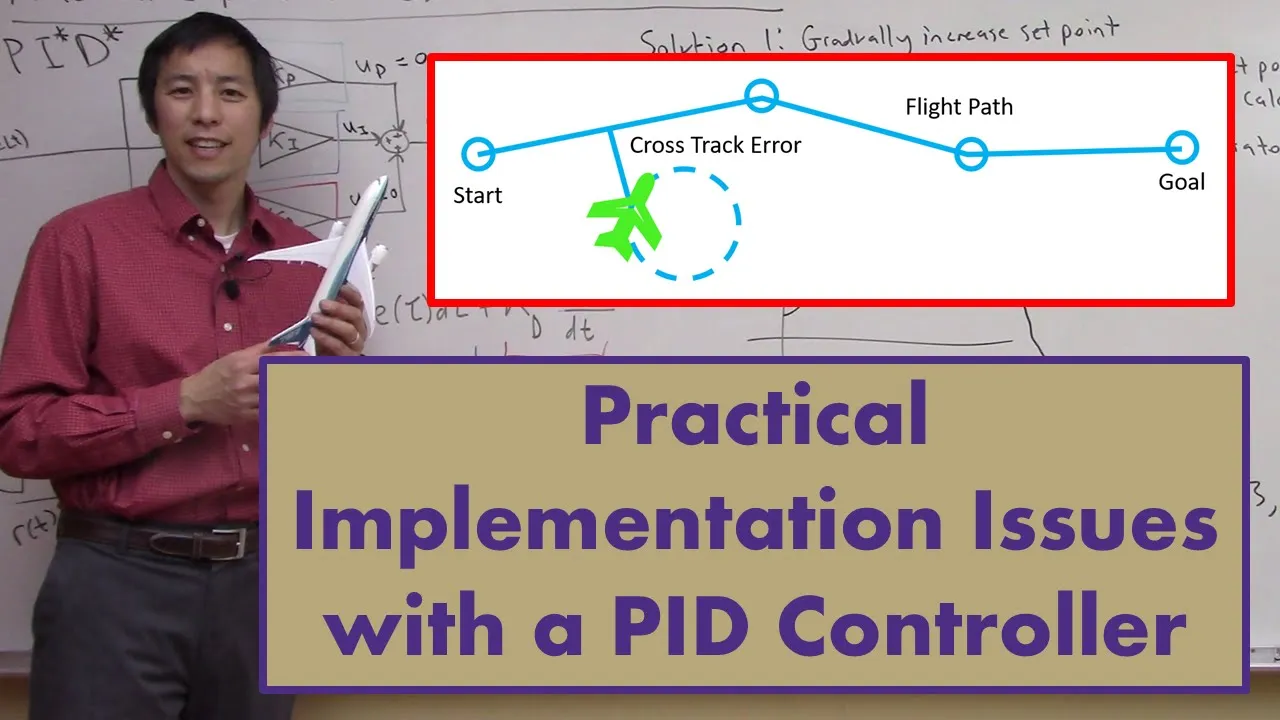

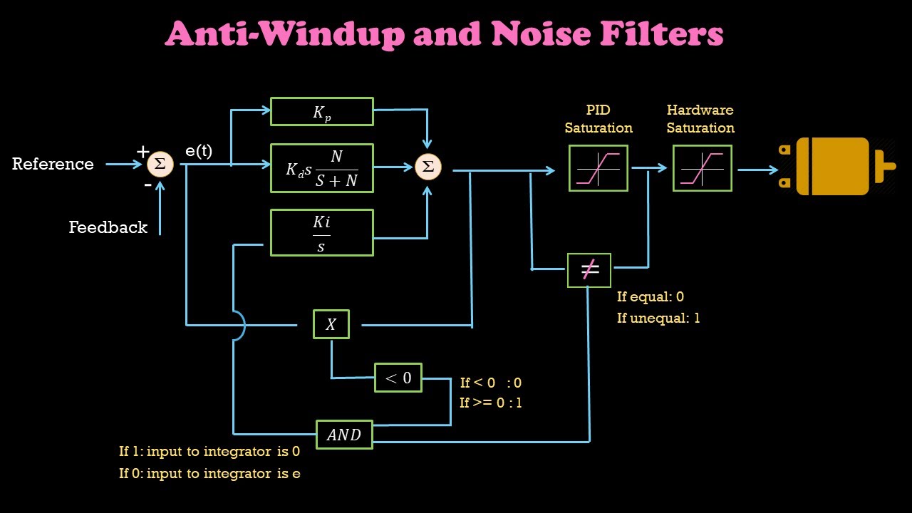
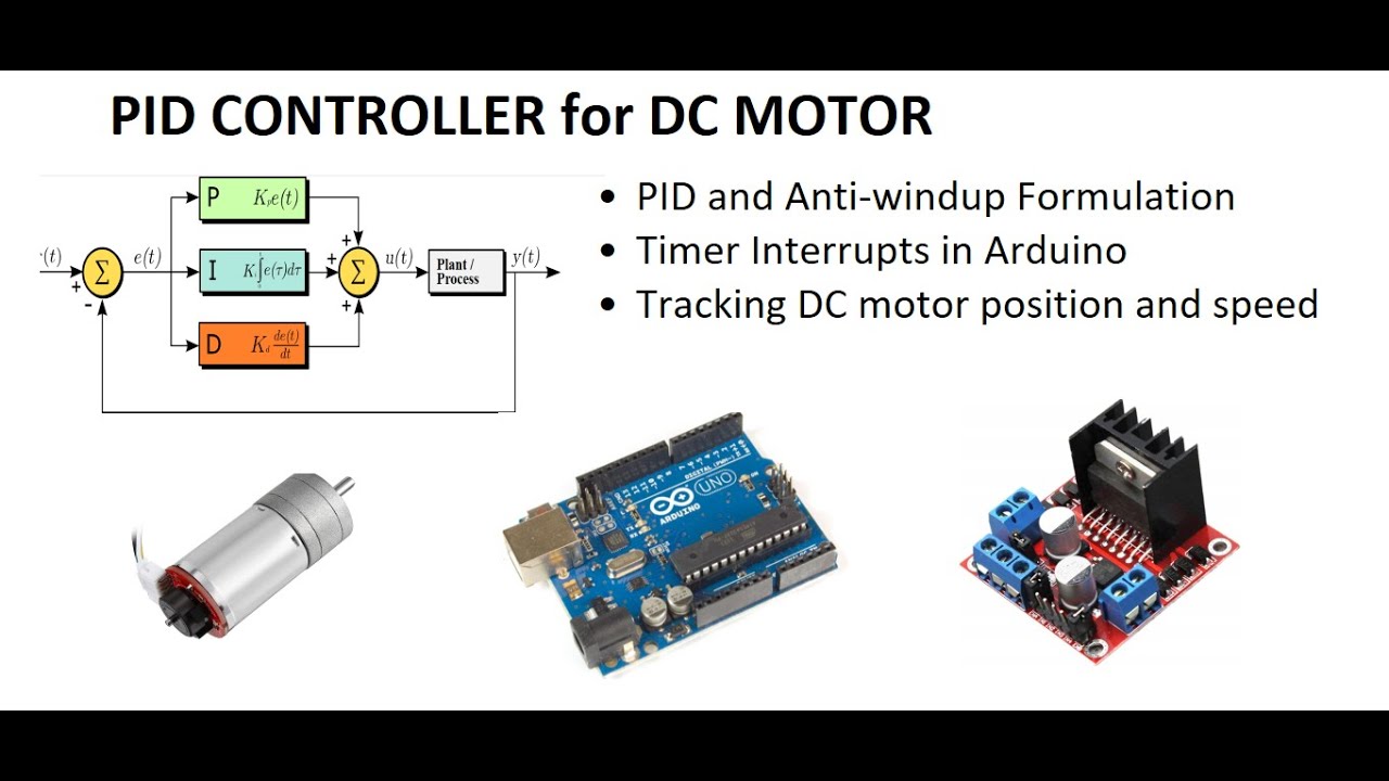

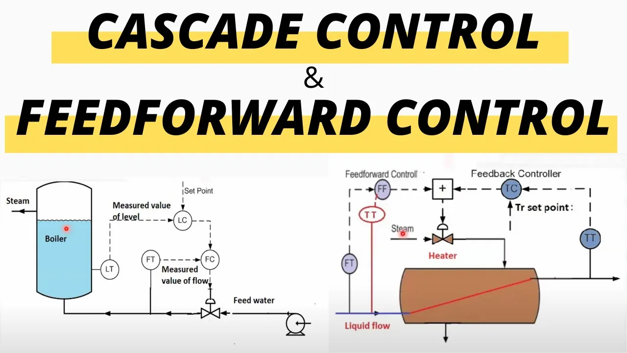

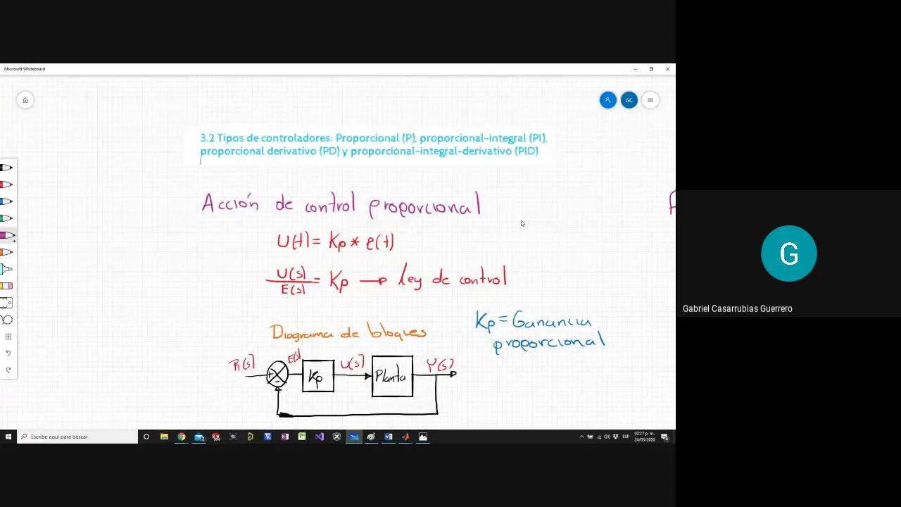


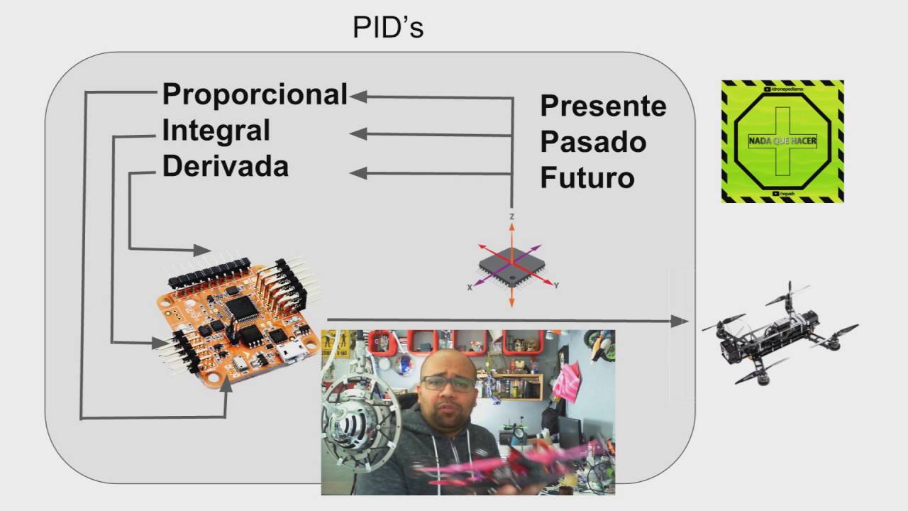



A PID (Proportional-Integral-Derivative) controller is a feedback control system that continuously adjusts an output based on the difference between a desired setpoint and the actual measured value. The controller calculates three correction terms: the proportional term (P) which responds linearly to current error, the integral term (I) which accumulates past errors to eliminate steady-state offset, and the derivative term (D) which predicts future error based on the rate of change. These three terms are combined with adjustable gain coefficients (KP, KI, KD) to produce an output signal that drives the system toward the target value. In practice, the controller runs in a continuous loop, measuring the actual value, computing the error, applying the PID formula, and adjusting the output accordingly. The effectiveness of a PID controller depends heavily on proper tuning of the gain values, which requires balancing responsiveness against stability and oscillation.
Arduino PID Controller Implementation Explained Step by Step
Added:hey and welcome everybody to another video so in my last video I talked a little bit about the I was talking about the ball and beam machine I talked a little bit about the PID controller and how the control Loop works and stuff like that it was a very cursory glance over it and I specifically said in that video that I'm not going to go into the details about how a PID controller actually works and that kind of stuff because it's an entire Topic in its own right and I said that I was probably going to do a small video maybe explaining about how PID Works in some detail so I decided to do that here and that's this video so I've got a really simple example that I fired up um on a written on an Arduino I have the code for it here so what we're going to do is we're going to step through this code and we're going to talk about it we're going to try and understand a little bit about how it works I'm gonna use an example I'm going to basically turn it on I'm going to plot the outputs here so you'll be able to see kind of in real time exactly how it works and I'll try and explain a little bit about it this is going to be again like a really cursory sort of overview of the whole thing because this is an incredibly Deep Field there's a lot of maths behind it in the real world and you can you know get into it really really deeply we're just going to kind of go over it at the high level hopefully enough for you guys to understand how it works and maybe be able to implement your own one so yeah that's job in um okay so first of all I think I should talk about exactly what it is we're going to be controlling because obviously a PID controller isn't much use if you don't have an actual thing to control so for that I have this really simple little circuit thrown together on a breadboard and the lighting is not amazing hopefully you can see that so it's an Arduino Nano here and we've got some resistors and some capacitors and there's a little LED there that's just for me to see an indication of what's going on so you don't need to worry too much about the actual circuit that's there that's not super important for this case again I might do a video in the future about that circuit in particular because it is quite interesting and I can explain a bit detail what it's doing but effectively all you need to know is that it's sort of it's a filter basically so what we're going to control is we have the analog output of the Arduino and we have the analog input of the Arduino that's going to read so what we're going to do is we're going to start off the program the program is going to say hey I want to set my output voltage to be a certain value and the PID Loop is going to run on the Arduino it's going to start you know increasing the output voltage that output voltage is going to go onto the circuit it's going to get read by the input side of it to read what that value is and then their PID controller will work in a loop to get that voltage to be exactly the voltage we want it to be now the reason for the filter is it's a little bit uh nuanced but basically when you set the analog output voltage of on an Arduino you're not just setting an actual you know a normal DC level what you're actually doing is you're performing pulse width modulation so you've got like a square train of pulses where the sort of RMS the average kind of value is going to vary to some DC level depending on how wide the pulses are so that's yeah sort of what we're doing but the thing is when you try and read that in on the on the um analog input side on the read side of things it actually won't be a nice smooth value because it is pulsing um so the reason we have the filter is we put the pulses in and then it goes through the filter and then on the far side of the filter what goes back into the Arduino is the input is more or less a smooth DC voltage I'll explain I think I will do a video explaining exactly how that filtering process works um that'll be for another time so just trust me that that happens effectively what I have is the analog output of my Arduino is going to an analog input of the Arduino and it's creating a feedback loop inside it inside the Arduino there's a PID controller which is setting all the values so that we get the voltage value out that we want that's the scene of what we're trying to do so with that said let's have a look at the code and see if we can figure out how that works um so the first of all we have our setup code I will come back to this it's not hugely important um yeah there's some values in here again with the these are some config values I'll come back to them once I've described how we're actually going to do what we're doing um simple ones I can say straight off here we have some input and output pins so we have our output is dd3 which is digital pin 3 which is the pwm pin and then our input pin is our analog pin zero could be any of them you just need to be able to read the pin so let's have a look then at our main Loop what we're doing so we keep track of time as we're running through it because that's important for a PID Loop needs to know how much time has passed for every single Loop that you've done so at the start of this first thing we do is we use the Millis method which returns I think it Returns the amount of milliseconds since the application started running I believe it tops out at 50 days or something like that so that'll just keep counting incrementing so that gives us a time stamp in milliseconds um we have like a last time which is initialized to zero at the oh that's not initialize it yeah well that will be initial yeah it is initialized to zero at the start so effectively we say that as far as we're concerned the application started running at zero and everything on from that is um however's time has passed the first time this gets hit um we get this DT value that we calculate which is DT would be a civil a kind of a common notation for a period of time delta T um DT so it's basically this is the loop time so it's how much time has passed since the last time you made a recording so for the first time it's you know contrived example but you know as you every time you do this you update the last value last time with the current value so the difference between the two is your delta T or how much time has passed since the last Loop you did um in this case we then divided by one thousand so we get a value in seconds as opposed to a value in milliseconds which is fine um so then we look yeah so a big part of what this PID controller actually does um so you'll see I'll throw a graphic up here a diagram of how it works but basically what we have is you have something you want to control you have some feedback loop where it's taking a value from the output and pushing it back to the input and you have some set point that's setting the desired position or the desired value for what you want that to be the input into the system is always or the input into the PID controller is always going to be well what's the actual value that I got from my output I compared to what the desired value was so we call that the error signal basically so in this case it's very simple we can read our actual value from the analog read command on the input pin and this scaling is just because the output values are between 0 and 255 for pwm and the analog read values are value between 0 and 1024 which maps to 0.5 volts so they both mean the same thing it's just different scales so this just lets me scale them back to be the same I get my actual value and I compare that to my set point value so the set point I can figure up here and I'm setting it to 75 so in this case what's that that's about 75 is what is it like 1.2 volts something like that I don't know it's a it's not a very high voltage it's pretty small um and so we compare the actual value that we read to the set point value and we calculate the error so the error signal it will be the input into the PID controller as you can see from the diagram um oh yeah that's what we're operating on so the entire goal of the PID controller is within this Loop its entire goal is to squash that error down as small as it can possibly be and get it so with each successive run that it goes on the idea is that that error gets smaller and smaller and smaller and smaller until it either completely disappears or it gets to a certain tolerance where you're happy with it so you would work at your percentage error at the very end and you'd say okay if it's within one percent I'm happy with that and you know that's generally how you would spec this sort of thing so in our code then we compute our error and then we use our error and we pass it into our PID method here and it spits out the output value so then the output value is what you need to try and is what you're supposed to set it's so it's basically the drive signal for for the for what's going to change the output in our case that's this analog right and it effectively is setting what the pwm pulse width should be to try and get the value back around to be what we want um yeah I'm just glossing over that for the moment um I'll talk about that in a second what the actual how we compute the PID value um then what else do we do here yeah so then that's actually pretty much it um here I'm just printing out these values so this is just so that on the plotter we can see um some nice graphs and then I have this delay down here which is a delay of 300 milliseconds now the thing with this is um this isn't how you would do it in practice in practice you want your PID controller to run quite fast and so that it can respond quickly enough to changing circumstances um for this example I've deliberately delayed it so that you can see it more clearly on the screen so you can see the wave changing as we as the PID controller runs in practice this would be much faster it just so happens that the standard built-in USB serial monitor it yeah it's not great for this sort of stuff in truth debugging stuff but anyway it's just for visualization purposes here um Okay so with all that said let's talk about the actual values themselves or you know calculating what the PID how the PID controller actually calculates the output so let's go here okay we've got our error signal that comes in and the idea of PID adds this clue isn't the name uh it stands it's three letters that stand for three things so it's proportional integral and derivative now that I'll get into it I'll just try to try to think through this on my feet I'm doing this live I try to think through it in my feed a little bit about the best way to explain it but effectively we have some error signal we want to take that error signal and we want to adjust our output values based on three different um computations on that error signal so the first is we want some proportional amount um of change based on the error we want and the integral an integral amount of change and we want some sort of derivative change so for the proportional case that's the simplest one to describe basically this is if you can imagine it's sort of just scaling the output value so if the error signal is one the output will be 1 times some value and that's just a straight proportional shift so if you had if your error was just basically oh it's always off by one it's always off by one well that just means I just basically want to add a little bit to that each time just to shift it up the way so what we do is we calculate our proportional term in this case we just say well the proportional term is just always equal to the error and then we multiply that proportional term by this gain value here don't worry about what's called a gain this is a term that comes from signals processing and stuff like that and how it actually works if you look at all the maps we call it again it's basically just a constant value that we multiply it by which you know shifts by how much this contributes to the overall output so in our case we have our proportional value that's just equal to the error and it's times something KP so in our example the code that I have set up here I have KP set to 0.8 now that works here but you've no idea it could be any value this value could be a hundred it could be a thousand for your whatever system you're trying to control depending on your units and all sorts of things in this case 0.8 happens to be the value that I've chosen I'm also not going to get into the higher details about really good ways of tuning PID controllers it's kind of a little bit of an art form tuning pod controllers there's loads of methods out there for doing it you can read up how to do it but they very much change from different machines different types of systems you're trying to control all sorts of different stuff so I won't get into them in huge values I'll just say that there is kind of some skill involved in doing it as opposed to just knowing um kind of a method um okay so that's our first term a proportional term it's sort of just a like a linear kind of offset term simple as that next term we have is our integral term so this is integral in the mathematical sense of integration so when you have integration effectively what we do what integration does is if you have some waveform or something like that when you integrate it over time you're effectively get the area underneath the curve the area that that curve bounds is what the integral is so if you get the integral of the error signal you're effectively adding all the errors together as you go to get some sort of value so if you could imagine your error just kept increasing so you kept getting further and further away from your target value the sum of that error is going to balloon and get really really big so what this does effectively is it's trying to fight against that it's trying to respond in a way that says no no that needs to be much smaller so the bigger it gets the the bigger the error gets overall than the larger this term will get which will help which is gonna the idea is it'll help to push the error back down again that's kind of the rough intuition about what it's doing the way we calculate that is it's just a value that we add to constantly and what we do is we add the error times the DT that we calculated um again from integration this is sort of a rough approximation of a numerical integral it basically is if you know the width of time that's passed and you know the value at this point you multiply them together and that gives you like a rectangle space that rectangle is a rough approximation for the area under the curve at that point there's loads of other different ways of doing this you can make this better by adding in different types of numerical integration systems this is the most basic one you could possibly do um but yeah this value roughly speaking if the error continues to increase over time that integral value will continue to get bigger and contribute back into the PID controller more and more and again it has its own gain so you can decide buy him what you want that to actually influence the output value which is what that gain does so final term our derivative term so the derivative term um again so from mathematics if you take the derivative of something you're basically looking at the so if it's if it's based around time so if it's something with respect to time is what we'd say for a derivative you're basically looking at how the rate of change of that value so say the rate of change of distance over time is what we call velocity and that's you know it's it's how much the distance that you're measuring is changing over time and that defines how fast that's changing which is velocity so in our case when we look at the derivative of the error it's basically the rate of change of the error over time so effectively if you could imagine that we have our signal and its value is changing if it suddenly jerks in value so that that um the error signal now has shot up in value that's going to have a really high um rate of change and in which case then your derivative term is going to get quite big and this is going to want to squash that value down again so the derivative term is kind of a weird one in terms of I said I wasn't going to get into about like you know the gains and stuff like that but typically derivative gains we would have them to be quite small because if you have something that oscillates very quickly the rate of change of that is very fast and that can lead to massive like explosions in the value of the derivative term which can lead to instability in the system overall so usually we keep those values typically they're kept quite small and often they're not used at all so that's another thing to say the general term of this is a PID controller which is a proportional integral a derivative controller boss some systems will be perfectly stable with just a proportional term in which case it'll just be a p controller or is another term phase lead and phase lag which are special cases of PID controllers I actually can't remember which ones are which but doesn't matter that's you can look that up on your own if you want to um but yeah so say if we were to just ignore derivative terms in this and we just use proportional and integral we would have a p i controller or you could just ignore integral terms and you could have a ped controller um so yeah that's that's a little bit extra detail but yeah it's all effectively the same thing the same algorithm runs you just basically turn one of these to zero say um and then that would completely remove the influences that term has on the overall output so then to get the overall output at the end then we just sum all those together and that gives us our output um we also need to keep track of for the derivative term I should have said this yeah so we have the error and we have some previous error measurement which was like the last error measurement that we had so to figure out the rate of change of that we take the difference between them and divide by the time period and that gives us the rate of change which effectively is the derivative um sort of numerically so again this is a really rough numerical approximation to the actual thing you can use numerical methods to solve these better but this is just a really basic example of it so that is more or less it in terms of explaining how this works and explaining the coding behind it all um the next thing I want to do is I want to turn it on and show you guys live on the screen what it looks like how it runs maybe mess with some values and try and explain a little bit more about what impacts they have um I should also say that all this code will be on my GitHub so I'll take this file and stick it up on GitHub you can have a look at it downloaded play with it make changes to it um just there for reference I'll put a link in the description excuse me Okay so let's turn it on and see what it does so I'll hit the reset button on my Arduino I'll kick this guy off and what we'll see is restarted I will start at a value of zero will have a set point value up here of 75 and the goal is that this value which is starts at zero should finish at 75 and it should stay there as well and that's the ultimately what we're trying to do with the control we started some value we tell it I want you to be at that value and then it goes calculates how it gets there and then it settles there and stays there that's the whole idea of PID controller uh yeah that's what it does let's kick that off and see what happens so I'll restart the Arduino click run on this so this is moving now and it's I have it padded so that yeah there's a there we go and there you have it so that's how that's literally the system response you're looking at it in real time so it's going to stop this to talk about it so what we're looking at here if you've know a little bit about systems if you've ever studied that or you might have seen a graph like this before and this is a really common type of graph it's what we call a second order system response you don't have to worry about what that means you look it up if you want but effectively this is a really really common graph that you will see of a system operating uh with a PID controller so we started off at zero the PID controller kicked in immediately when we got to here and it said well hold on the error here is quite large so I need to adjust my output value to make that error smaller so the PID controller started Computing values and effectively it needed to have a large response because the error was large so that large response kicked some values up but the thing is it went way over the line and then at that point it went hold on we've gone too far in the in the opposite direction now we need to tune those values back down again so we did that and then it realized it had gone too much in the fire in the opposite direction you get the picture so it just kind of Wiggles its way down to try and get to its Target value so in this case it's not settling down fully um this and this kind of system response I deliberately tuned it this way so that you could see this sort of the way it overshoots and then comes back down and then oscillates out to what we would call a steady state so it's stable but it is there's a little oscillation in it now if you were to look at the error for this it's very very small so if I just keep hit run so that it keeps running um we'll see now this will zoom in and we'll see by how much that value changes so here we go this is basically the steady state now that it's running in and you'll see that the error is quite small so it's oscillating set point to 75 it's oscillating between 76 and 74 so it's plus or minus one which in this case is we would say the steady state error is two which is 74 76 minus 74.
so in terms of the target value 75 an error of 2 as a percentage of what is that that's uh what is it so uh two divided by 75 times 100 so it's 2.6 so 2.7 percent error which isn't too bad that's that's pretty low it's a so for some applications in real life that might be way too much you may need way smaller error than that but for other applications that might be just fine so the fact that it isn't just a set flat value that's not that bad it's it's oscillating a little bit and that's okay for our case I'm saying it's okay for this case but yeah that that's basically what that looks like so let's imagine now so I talked a little bit about you know that the the values of our our gains here are what decides kind of what that graph looks like really so let's say for example here I'm going to take this and the proportional gain it was 0.8 I'm going to turn this up to 1.2 and let's see what that does so upload the code and then this will reset itself to a flat line yeah excuse me I know this should kick back up and we'll see what happens so we get our big spike and we get our damping effect which is starting to take effect but you see this now is oscillating way more so this is again it's a stable responses and it doesn't shoot off to Infinity it's it's pretty stable but it's quite a large oscillation so the error here is pretty large and you see it's also in between about 65 and a little bit lower than 85 so the error here the percentage error here is going to be quite large and this might be an unacceptable amount of air to have in the steady state version um so yeah this just shows you how you tune basically it's just a very simple example of how you can tune your system so let's say if I was to drop this down to a little lower than it was and see what that does um this should it might undershoot it or it might just settle down a bit quicker let's have a look and see what happens yeah so that actually settled down quite quickly um so that's a little bit so it's a little bit less overshoot than the 0.8 value and it's settled down pretty quickly um but yeah that's gonna look more or less the same probably plus or minus one in the air when we uh when we look at it so I I think that's like pretty much everything I wanted to talk about like you could talk for hours about this like I studied this way back in college you know 10 10 years ago and we studied this in so much detail endless amounts of labs and experiments and all sorts of different graphs and things you could look at and how changing one value can push the whole thing around and all sorts of other techniques around tuning this and everything but I think I've just given you the basic overview of how this works like if you know about that much that I've described you could probably be able to set up a system and get it you know being controlled with a PID controller um yeah actually one thing I did want to show this is kind of interesting so you can have a look at the error signal and we can plot that over time so effectively what would be what this will look like is this will show us what the error looks like on the signal it looks basically the same as this except it'll be sort of like in Reverse um so if I throw that on yeah I'll put that we have a look at that oh oh afterwards sitting in just restart it so the error starts quite high so effectively the error starts at like you know 75 and then we see it drops down quite quickly and then in the same pattern and then it'll oscillate around and so this is the error signal that's the input for the whole thing uh and so we saw that the error started High the error was 75 while the output value is zero then it very quickly dropped way down shot very far under then shot a little bit over and then settled down and now we're at this steady state value where it's the error is oscillating between -1 and 1 occasionally it's at zero and yeah that's it so excuse me again um yeah so I don't think I have anything else to say about this I could go on for hours we could just sit here and I could play with values and we could look at the outputs on the graphs but um that'll get tiresome uh after a while what I would say for you guys is to have a look if you download this code and set it up and running um have a look and see what you can get out of it and yeah play with some values like you know increase the gain values decrease the gain value see what that does to the graph and try and build a bit of an intuition around how does this work if I push this value what does that do how does it look and all that sort of stuff because that can really help kind of get this into your head about how it actually works um in a in a practical Hands-On sense as opposed to just trying to understand all the maths behind it which is quite abstract um so yeah I'm gonna leave it here I hope everyone enjoyed that I hope people learn from us um yeah if you have any questions leave them down in the comments I'll do my best to get back to you and answer as best I can um and yeah in terms of this circuit what it is I'll throw a circuit diagram somewhere linked with the codes you can build this yourself and just see what it is um and also I'll probably do a video where I talk about um how this circuit works and you know some simulations and stuff behind it a little bit more Theory um so yeah that's it thanks for watching guys and I will see you in the next one bye
Up Next
Proportional, Derivative, and Integral Controllers in Control Systems
@Ekeeda
69.6K views•2018-07-06

Ultrasonic Transducers: Resonant Frequency Measurement and Horn Design
@imajeenyus42
229.9K views•2017-02-22

Polymer Environmental Degradation: Mechanisms & Stabilization
@iit
1.8K views•2012-07-10

How a Student's Question Saved a NYC Skyscraper from Collapse
@veritasium
22.8M views•2025-04-26
Related Study Plans & Knowledge Roadmaps
Structured learning paths in Engineering