





![[Full Breakdown] PID for DC Motor Position Control using Rotary Potentiometer](https://i.ytimg.com/vi_webp/-P-6bMbQh1E/maxresdefault.webp)
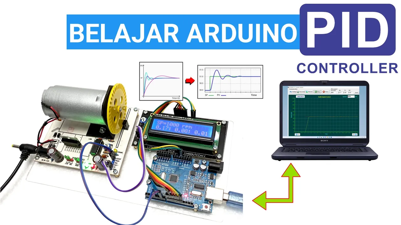

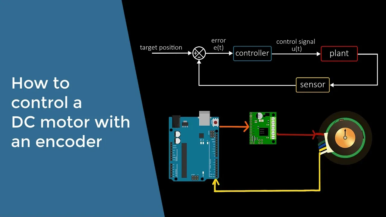


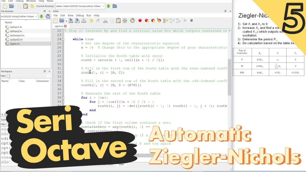

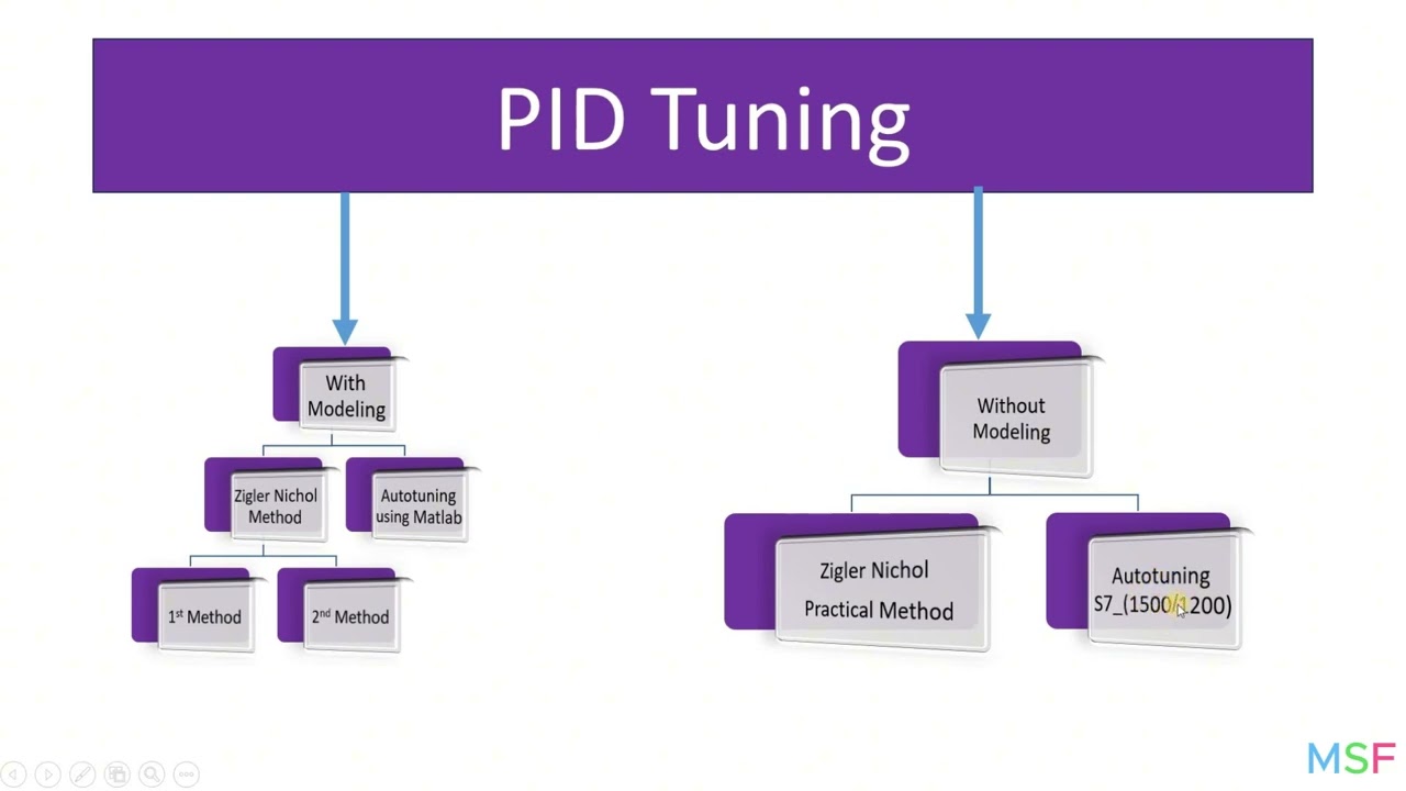










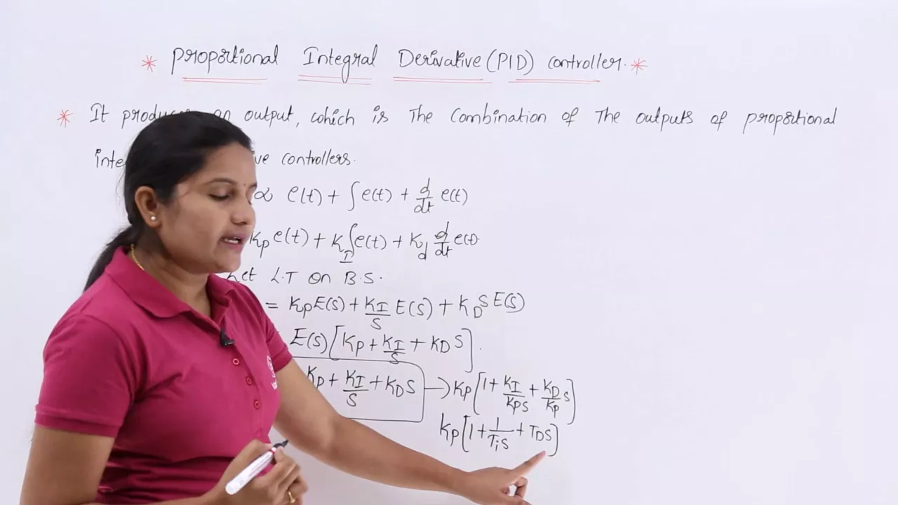
A PID (Proportional-Integral-Derivative) controller is a feedback control system that minimizes the error between a desired trajectory and actual system output by combining three correction terms: proportional (present error), integral (accumulated past error), and derivative (predicted future error). In this Arduino implementation for DC motor control, the controller uses trapezoidal integration and backward difference methods to calculate the control signal, while anti-windup techniques prevent the integrator from saturating when the motor reaches its voltage limits. The system employs hardware timer interrupts (Arduino Uno's Timer 1 in CTC mode with 64 prescaler) to ensure precise 50ms sampling intervals, and quadrature encoders with external interrupts to measure motor position and speed for closed-loop tracking.
PID Controller for DC Motor with Arduino: Speed and Position Tracking
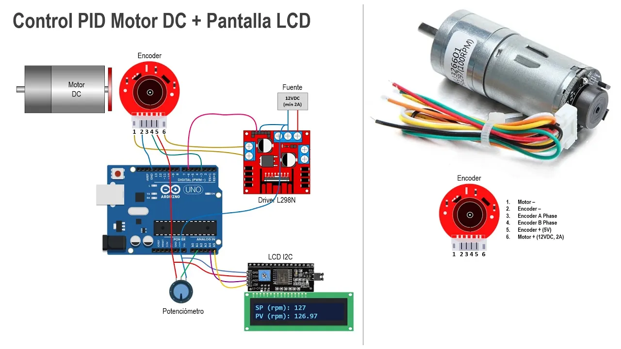
Added:hey guys so this is gonna be a very comprehensive video about PID controller I will be controlling a DC motor and now we'll go over a PID and the anti wind-up concept and now basically learn how to formulate it in in inside the Arduino code we'll use the timer interrupts as well Arduino so we can measure time and basically keep track of events and now use that met your time in or between PID controller time step we're gonna track DC motor position and speed will have a desired predefined trajectory and we'll have our motor follow that trajectory as close as possible using the PID controller I'm gonna quickly go over the just just a basic overview of the code structure we'll get into the code a little bit later in this video but I would kind of give you idea like that will basically be defining our variables and pin numbers for the motors and encoders components then we'll define some functions the encoder function to measure rpm and position of the motor motor driver function where we'll be writing voltage to the motor driver so we can drive the motor accordingly and we'll also have a timer interrupt function as well to measure time then we'll have a setup function main setup function will set up the serial to output values we'll also have to set up our encoder so we can call that function same thing for the motor driver and the timer interrupt then we'll have a main loop this is where the meat of this code is gonna be so we're gonna calculate the actual angular speed and the position will also define the trajectory of our speed and position in this loop and will basically calculate the error the difference between those two and will basically minimize the error using the PID and the MT wind-up formulation and that error will basically go to the voltage which will be written to the driver that will control the DC motor so let's go over the PID controller so what's PID PID is basically a proportional integrator and a derivative off the error and what is it or exactly so let's say if you have a function UT and there's time there and this is this is our desired trajectory in this case it's a step function and this is our actual component could be a motor or a different sensor or some kind of component trying to follow that trajectory let's say it goes and gets it get starts moving away from the red line and at that point just just for example say go see from that point and on the blue line and to the red line the difference between those two points is basically is our error so our controller we're basically calculate the error use that error to move close and close to the red line and at every point it will basically calculate the error and try to get closer and closer and closer to the red line and eventually we'll reach a steady state this is where our gain values for these controllers come into play so if our gain valleys are correct or appropriate then we can reduce the time it takes to get to the steady-state and less LSU undershirt or overshoot so let's go over the PID formulation so let's say we have this a UT this is our controlling function that's what we're going to control and we'll have the gain of proportional controller or multiply it by the error at point K so let me just change this T to K as well so we're talking will do this in discrete time K index and now we'll add the integrator controller to that so will and will write the gain for integrator times the integration of the error with respect to T plus the gain of derivative controller times the derivative of the error and [Music] basically the integration takes the past data the derivative takes the future data and the KP is the present so the proportional controller is pretty simple you just multiply the gain to the error that are you know calculate based on the difference between the actual trajectory and the desired trajectory let's look at the integration controller like how we're gonna integrate the error so we'll use the trapezoidal method to calculate this so just overview a trapezoidal method is basically you have a graph here you have curve and let's say there are two points on this curve I said this one's caves it's K minus 1 and the distance between those is Delta T that's our time step and let's say we the the integration is basically just the area under the curve I mean you can use the rectangular method basically just you know finding the highest point and just multiplying by the delta T to find a rectangle but we're going to use the trapezoidal so we'll find a sloped line from from those two points and find the average point and multiply by the T to find the a little more accurate area under the curve so the way you're gonna write that in Arduino is let's say you define a variable int integration area at point K so we'll write that equal to integration error k minus one the previous error plus e the error at K plus error at K minus 1 over 2 this is basically the average of that red line and multiplied with the Delta T to find the area under the curve and the way you're gonna find the derivative controller we're gonna find the derivative off the error is using the backward difference method there's a whole video on my channel talks about different differences method how to use those maybe take a look if you get a chance so you take the error derivative of the error is basically just the error at point K minus the error at previous point which is K minus 1 over the time step 2 delta T so this is basically our formulation that we're going to use in the code D that integration equation and this derivative equation let's look at the encoder how are we gonna implement this in our code and what is exactly a controller encoder so we're gonna use a DC motor like this with the encoder attached to its back and this encoder basically has these two sensors here these are two Hall effect sensors and there is a magnet on this black disk and when this shaft rotates that disk and the magnet rotates around these two sensors and creates square pulses so there are two sensor that creates two square pulses and this is a little diagram of how this quadrature encoder really works so if pin a is leading pin B which means pin beak pin a goes up before pin B that means it's a clockwise rotation well I say if pin B goes up before pin a that means the pulse B is leading pulse a and creates a counterclockwise rotation now how question is how do we implement this logic in our doing a code so we're going to use a external timer interrupts to measure the rotary pulses because using just a delay function it's not gonna give you an accurate reading it's gonna be very difficult to solve timing problems without using the interrupts external interrupts functions so let's write this into this in new Ord we know code so first thing you want to do is you want to define pins so we have a pin number pin 2 and pin 3 and also when using external interrupts you have to use pin 2 and pin 3 if you're using Arduino Uno so if you're using any other between Omega or something you might have to check the datasheet to figure out what pin to use so we have to find those two pins and we also wanted to find the encoder count this is something that will be counted every time the the shaft is rotated around three sensors and through that we're gonna calculate the position and the RPM of the motor let's define this function the ISR the interrupt service routine for pin a so I'm gonna adjust my screen a little bit so I can simultaneously right there you go so this is a logic here for pin a so this is a pin a function so this function is this interrupt function is only called when there is a change in pin a so like if it's going from high to low or low to high so let's say if if we have these two lines these two pulses one's a and the other ones B and we're looking at pin a change so let's say first condition is pain equal to high switching from low to high so searching at these two places and we also have to check for pin B condition and we're saying if pin B is low there you go so in this case it's low not in this case so that means our rotation is clockwise so we're gonna say our encoder will count positively so it will increment positively and and if you use the else function where it means that penne is switching from a tool sorry it's searching from high to low it's switching from high to low switching at this point at this point and now I gotta also check for pin B status which is already at low so it's not at this point it's on this point right here so we know the the rotation is counterclockwise so we'll say the encoder is moving to the negative side so it will be incremented negatively similarly we will have a another condition just like pin B is high and pin a is switching from low to high or high to low and we'll change the encoder count accordingly so now we're gonna make another function for pin B as well so we have another encoder B function so in this case we were looking at pin B switching at state and also simultaneously checking for pin a so it's a similar concept as to pin a function pin B is similar so now what we'll do define our main void setup function here so in this you wanna you want to set up these interrupt pins and the inner functions so you first need to find the pin you say the pin mode and you'll use the built are doing a built-in input pull-up function and and we'll also define the function for the attached interrupt which is the external interrupt function so this is the syntax I mean the Arduino uses you write digitally to interrupts and you write to the pin you define and then you call the function and then you look for the change I mean there are several other things you can look for rise or there's a few other built-in function that you can use but in this case we're just gonna look for changes and then call the function ok we'll define our void main loop function we'll define our variable data which is the angular position is equal to the encode account and over at the nine hundred I'll explain what nine hundred is coming from up a list to find the data pin in the beginning of the program so there's a floor variable data and we can also need a data previous value this will use that to calculate our pian so the encoder is basically divided by the nine hundred and nine hundred is just a value for count per revolution so that's the total number count in one revolution and then the encoder account just gets divided by that so we get true angular position so let's also define RPM and there so we'll define a float variable RPM and we'll go to the main loop and so for now we'll just use the built-in timing function inside the main loop will say T is equal to Millie's milli a milli second function but I'll show you how to use how to measure time using view timer interrupt when we get to the PID and as I said that nine hundred just account per revolution and the encoder account just get divided by it to get the angular position now we'll basically define our delta T so delta T is basically just the t minus the T previous so and also the RPM is just the derivative of theta which is using the backward difference method it's just theta minus the previous theta over the delta T delta T is getting divided by a thousand because I want my delta to be about fifty milliseconds so it's just fifty divided one thousand fifty milliseconds and dime sixty because we're doing a measurement in a minute and at the end of the loop we have to make sure that theta previous gets replaced with the current theta value so the loop can go on and so we get the difference between those same thing we got to do that to time the time previous gets replaced with tea I just realized that I forgot to define these two variables so I'm gonna have to go up and let's just define these unsigned long tea and tea previous how you send mishel iced tea previous to 0 and now what we'll do is we'll write the motor driver function so basically writing voltage to the motor driver that will run the motor so in order to do that first we need to define some pins for a deep motor so we say a constant bite pin we define a pwm pin because this is not just we're not just running at high and low we're running at variable speed and these are the pins pin 7 and pin 8 these are the direction of the motor one will be a positive the other won't be a negative direction now I think we also don't have to define the voltage variable for the motor what max voltage we want so let's define that so up here we'll say the voltage max is equal to 6 volt so I'm only using 6 volts but you can use any and I can also initialize the V equal to point 1 the initial B point you can leave it at 0 but I just did it for 0.1 just to make big difference and now we'll just write our motor driver function just above the setup function they say a motor driver which has two variables that's gonna the input variable is the voltage and voltage max so we need two voltage Max to map the PWM so we can control the speed accordingly and so this is that we're using the egg bit this is a big thing so 255 and that gets mapped to six volts and so there's some logic behind it so if the if condition basically says if the is greater than zero the direction pin one will be high and the other will be low that means if isn't positive then it most positive direction else when B is less than zero it will move in a negative direction which is the pin two which is high in pin one it's low and when there's no voltage both pins will be deactivated now we're just gonna write the analog voltage to the motor driver once we write the motor function we have to set up in our void setup function so we'll set up the pins we're saying these two pins are output and we'll go to our main loop and basically say that voltage will be written and we'll just write voltage to our driver function to run the motor all right let's look at the hardware timer interrupt so we can use Arduino clock to measure time so which will be much more accurate timing events so Arduino Uno has three timers that's timer to zero timer one and timer to so timer 2 is 8-bit timer one two 16-bit and timer 0 is also a fate which is from 0 to 55 and 6 5 5 3 5 and 0 255 the way we're going to use our time step frequency which is the delta T which is our 52nd 50 milliseconds and we're gonna actually use the Arduino is clock frequency and basically measure time like that so since our doing knows mega microcontrollers frequency is 16 megahertz we need to calculate something called output compare value which is equal to the Arduinos clock frequency of 16 megahertz and our delta T frequency which is just frequency will be just 1 over time which is 50 milliseconds times the prescaler subtracted by 1 so it will basically just be 16 million over 20 Hertz and the prescaler you get a few choices but prescaler so your prescaler is 1/8 64 256 and 1024 so whatever p scalar you use and DD and whatever output compared value that you get needs to fit inside one of these timers the timer 1 2 or 3 I'm sorry timer 0 1 or 2 so let's let's look at let's use 64 since I've already used it so the output compare value comes out to be 12 499 so this one actually fits and also one thing is it has to be an integer value so you can you cannot use any other prescaler and get a decimal value that would not work and this value also fits inside one of these timers bit so timer one it range is pretty large so it fits inside the timer 1 range so the way you're gonna write all this in this type the code is you will go to your void setup function you're gonna first you're gonna actually write the CLI command which basically stops the interrupts you have to stop the interrupts before you can set up the interrupts timer interrupts so the first one the TCC r1 a register is you gotta set it to zero so empty you gotta do two one B and then you initialize the counter value to zero and then this is this is the output compared value this is your output compare value at 12:40 now we just calculate it and then you gotta go and set the register one be using this command this is from one of the tables so if you're using that CTC mode you use that table and you set that value and and this is a pre scalar so this is this is also from a table out to show you that table so this table here if you're using a pre scalar so we're using a 64 prescaler up those 256 so if you're using a to 64-bit prescaler so in that case this CS 11 the cs10 these two clocks will be active and the C is 12 will be 0 so we have to make sure that we add this in our code so we'll go to our code and here it is so the CCS 11 and cs10 are active and the other ones not even listed and the last one here is you enable the timer compare interrupts so you have to enable it and the sei is just allowing the intros back online so we need to also define a function we're gonna use this built-in compare timer function and basically this we know this function this event will be happening every 50 millisecond because we set that timer and we'll just count every time it happens and we'll simply use that count in this main loop by using this condition we'll just say if if count is greater than count previous and I also need to define these values or this variable so I will go up and now let me see okay so I will have to define these two variables first and just initialize them to 0 so here I'm saying is if if count is greater than count previous I'm just calling the count that event I know that event is happening at every 50 milliseconds and so under that if condition everything will happen at 15 Mille second and make sure that you you replace the count previous with the new count value let's go over at the PID formulation inside the Arduino code so first thing what we want to do it we're going to define the error variable and also the integration error variable so it also define the pre error previous which will be in the lunch initialize to zero and same thing for the integration previous value as well and then what you want to do is you also want to define the RPM desired rpm variable so this will be our desired rpm trajectory that our motor will follow and the controller will try to get that as close as possible and we'll also define the max rpm variable as well this is already calculated it's not relevant in terms of finding the PID proper PID controller gains it's just to define the trajectory and this is how we're gonna define our trajectory we're gonna say rpm D is equal to rpm max times the sine wave of it and here is this is a sine function this is a but generally a matlab function but there's no built-in function arduino so we're gonna have to create one and now so we'll just create one here is another function is float sine will just take the x value and it says if X is greater than 0 it returns the positive value if X is smaller than 0 times negative value then now well we want to calculate the era's error it's just the difference between the desired trajectory minus the actual trajectory so it's just the RPM desired minus the RPM and this is the integration variable the the in T integration error variable the same thing as what we calculated in the beginning of the video see the integration error previous which is just the integration there K minus 1 and plus using the trapezoidal method and all this error will basically be the summation into a voltage variable so be KP times the error then the DK I so I'm gonna have to define those gains as well so let's just define I mean these are already I've already calculated them not calculator but found out through trial and error they there is no proper way to calculate these so all this will control the voltage to the controlling function and that'll be written into the motor driver now there is another problem something called anti wind-up so that happens when the integrator term becomes larger and larger and makes the voltage function go beyond its max voltage so if the system limits of our system is 6 volts but the but the integrator term can actually make that voltage term inside the program larger than 6 volts and that will not allow our rpm to reach stability will never be stable so all we want to do it want to use these code here saying that if V ever goes over v-max set that set that V equal to V Max so I set it to 6 volts and you change the integration term integration error term integration previous term and same thing you do that for when voltage goes below the minimum which is negative six I'm gonna to find that here so three men is negative six and so as soon as the voltage function goes below four negative six our if condition will set it to be minimum and now we also wanted to make sure that the end of the loop we set these previous values to its currents well current value and will basically write that voltage controlling function into the driver and control the motor like that and let me just compile this and okay before that let me just define the serial so I can output some of the values so I'm gonna output these RPM desired rpm and also our actual rpm and now let's also output time so I'm gonna just say it 0 for in count how it basically just goes into your one two three four five six and you just multiply been point well five so we can now get the 50 millisecond time step printed so show you this I'm not gonna go detail into how to wire this up I mean I think you can find a lot of resources out there they can show connect motor driver and coder and stuff so here's my motor driver the system motor DC motor with the encoder a at its back and the to call fake sensors and there's a tape here so we can see the revolution and the power supply is set to 6 volts so that's our max bolted supply voltage and there's a breadboard and you know I'm using the Arduino Uno and this one and now we'll test these in a minute I'm gonna upload this code now run it the serial plotter - oh the red our actual rpm and the for diner and the blue is just a time way in and you can see we're pretty close the dilute that you've seen the line and I mean too much unless you have other means to reduce all the it's phone add very well there's not much you except the big beginning one motor is basically oscillating it's going in different directions at a faster speed our motor is following that trajectory down even make that data to your math lab works just basically see D overall actually and now we'll do that in a minute here I'll just show you the graph because I'm not gonna really so we got our data for the speed but if you want to also control the position of the DC motor all you're gonna do is you're gonna create another variable for data D a desired trajectory for data and basically find the error using the desired data minus the actual data and we're gonna same thing voltage is still gonna be our controlling function then we'll write that into the motor driver and and now I'm just gonna I've exported to data from the speed using this serial monitor I've exported the time step I've exported the desired rpm and the RPM so the second column here is the desired rpm and the last column is the RPM and the first column is my time step and then there you go I have since you can plot this in a MATLAB you can see the x-axis is our time and Y is are the RPM so the blue line is a desired trajectory and the orange one is our actual one so there is the initial overshoot there and I mean you can change game values and try to optimize it more and there's some jitters there oscillation that's just due to friction um you can't really do much about the friction list you can find a way to reduce the friction there so that's about it that's PID controller and hopefully you guys learn something or video was helpful and if you guys think that then place like and subscribe thanks
Up Next

DIY Arduino Autopilot: Water Trial Performance Tuning
@newsaltsailing7756
4.1K views•2020-11-21

Ultrasonic Transducers: Resonant Frequency Measurement and Horn Design
@imajeenyus42
229.9K views•2017-02-22

Polymer Environmental Degradation: Mechanisms & Stabilization
@iit
1.8K views•2012-07-10

How a Student's Question Saved a NYC Skyscraper from Collapse
@veritasium
22.8M views•2025-04-26
Related Study Plans & Knowledge Roadmaps
Structured learning paths in Engineering