




![[사마귀 자동차역학] 76. 전달함수와 라플라스 변환](https://i.ytimg.com/vi/VfxPNGY8K3k/sddefault.jpg?sqp=-oaymwEmCIAFEOAD8quKqQMa8AEB-AH-CYAC0AWKAgwIABABGGUgZShlMA8=&rs=AOn4CLBzjC971XrO0aeoGNAM7FOeLzWh6Q)


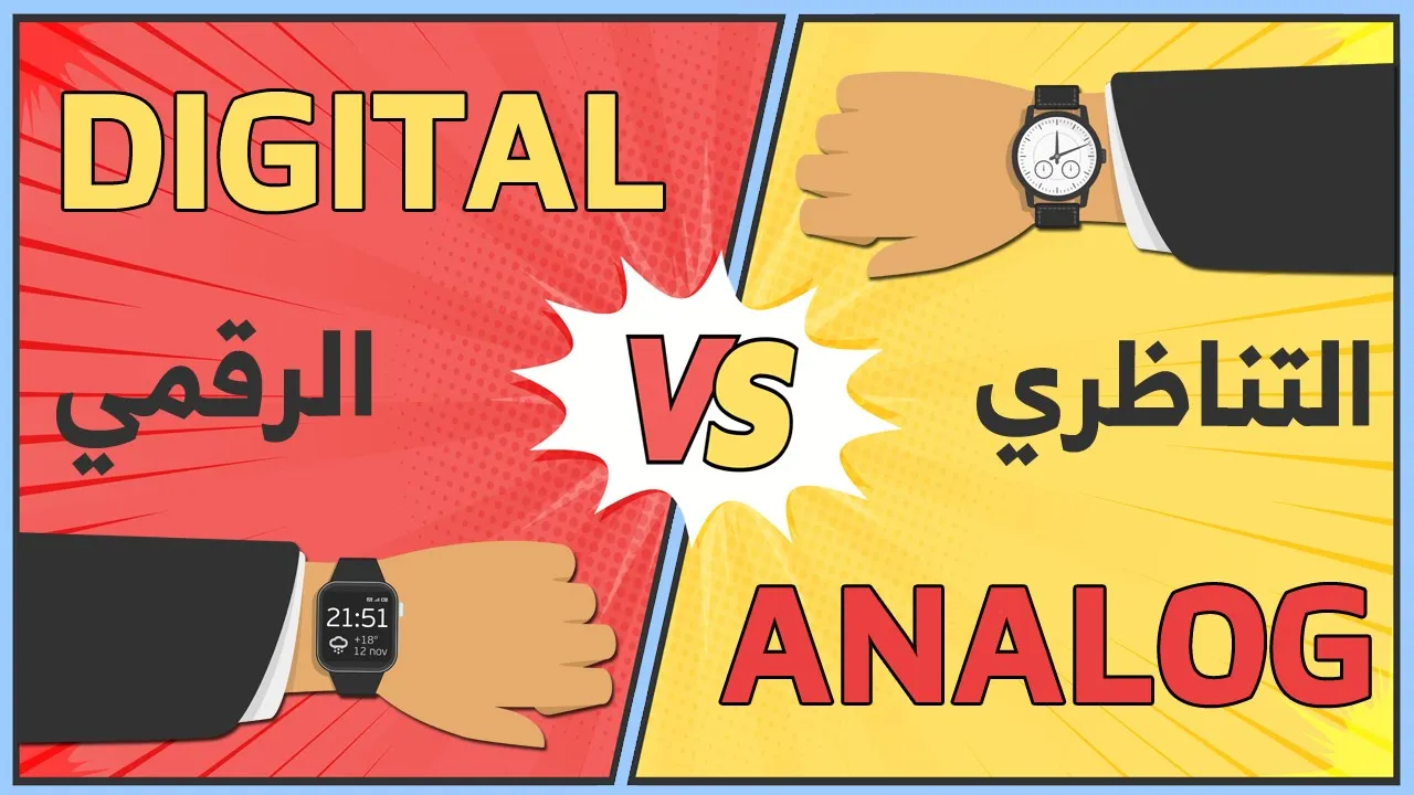













Controllers in control systems are devices that compare desired input with actual output to generate corrective signals; they are categorized into analog and digital types, with analog controllers further divided into three fundamental types: Proportional Controller (where the activating signal is proportional to the error signal, used for amplifying weak error signals and reducing steady-state error), Derivative Controller (where the activating signal is proportional to the derivative of the error signal, used for minimizing deviation and reducing maximum overshoot), and Integral Controller (where the activating signal is proportional to the integral of the error signal, used for eliminating steady-state offset). These basic controllers can be combined to form PD controllers (reducing overshoot without changing steady-state error), PI controllers (eliminating offset but potentially decreasing stability), and PID controllers (combining all three actions for comprehensive control with no offset, high accuracy, and improved stability).
Proportional, Derivative, and Integral Controllers in Control Systems
Added:Hello friends in this video we are going to study about the controllers used in the control system so let us start with our topic if we see the block diagram of a closed loop control system then it is like we have the input signal then output signal we have a feedback and we have the controller and the plot so let's see the block diagram of a closed loop control system this is our input RS and this is the output CS it is the error detector it is the control logic elements so this is the block diagram of a closed loop control system now in this block diagram the work of the error detector is to get the difference of the desired input this is the input which we desired and this is the output or the feedback signal so what this error detector does it calculates the difference or the deviation of the output signal from the desired input okay this is the feedback signal so it sees that how much our output is deviated from the input and it produced a signal the signal is called the activating signal and this activating signal is then given to the control logic elements so this complete set up the error detector plus this control logic elements they are collectively known as a controller so how we can define this controller a controller is one which so we can define the controller as a controller is button which compares the controlled values with the desired values and has a function to create the daeviation produced to correct the daeviation produced so what a controller is doing it is comparing the desired input and the controlled input this is our controlled input and this is the desired input so controller is comparing these two inputs it is thing it is checking that how much the control input is deviated from the desired input and it has a function to correct the deviation which is produced so this function it can be different so depending upon the function there are various types of controllers okay the controllers can be like analog controllers are there digital controllers are there depending upon the function which is used to connect the deviation so this is how we define our controller now let us see that what are the users of controllers the first use of controller is that it improves steady-state accuracy okay and how they can improve the steady-state error accuracy by reducing the steady-state error now as the steady-state error is decreasing and accuracy is improving also the stability also increases now controllers they also help in reducing the offsets in the system and maximum overshoot it can also be controlled by using the controllers controls also help in reducing the noise in the system so disturbances can be removed using the controllers also if the response of the system is slow then it can also be improved that is the response of the system can also be improved or it can be made faster so these are the uses of the controllers by they are used in DES for these reasons they are used in the control systems so first is the that they improve the steady-state accuracy and because accuracy is improved so stability is also improved also it helps in reducing the offsets in the system maximum overshoot of the system can be controlled it helps in reducing the noise signals produced in the system and also it helps in making the response of the system faster so these are the reasons why the controllers are used in the control system now let us study the various types of controllers used in the control system now these controllers they can be divided into two parts like analog controllers and discrete controllers controllers because we have studied like in the definition of the controllers that the controller it has a function so this function can be an analog function or it can be a discrete function so if it is an analog function then the controllers are called analog controllers or continuous controllers and if the function is discrete then the controllers are called digital controllers so first we will study about the analog controllers now in analog controllers the controlled variable that is the controlled output it can map any value within the range of the controlled output so in controlled in analog controllers the controlled variable so the control variable can have any value within the range of the controller's output and if we are using the automatic control scheme so in the automatic control scheme the controller is automatically going to compare the controlled output and that is the control condition value with the desired value and it will produce a function which is going to affect the output and it will try to make the output close to the desired output okay so in automatic so in automatic control scheme the controller it is going to compare the controlled value with the desired value and then it will automatically correct is any type of deviation between the deviation of the control value from the desired value and this correction it can it is made by our function and depending upon the function used to correct this deviation there are three types of controllers first is the proportional controller second is derivative controller and third is the integral controller now by the name you can understand that in proportional controller the function which is used it is having the proportionality between the functions okay and derivative controller it will have derivative function and in integral controller it will have integration function okay so depending upon the function used to correct this deviation there are three types of controllers first is proportional so this integral controller and there are also controller which is a combination of these three types of controllers so there are also we have proportional derivative controller then we have proportional integral controller and we have the controller which is the combination of these three controllers like proportional derivative and integral controller so it is named as proportional in T derivative and integral controller so there can be these six types of controllers are there in the analog controllers now we are going to study these controllers one by one so let's start with the proportional controller so the first controller is the proportional controller now in proportional controller as we have seen here in the block diagram that the controller compares the values with the desired values and it has a function so here the function is the proportional function so in this proportional controller the activating signal it will be proportional to the error signal okay error signal is the difference of the reference input and the feedback signal so this actuated signal is going to be proportional to the error signal in the proportion controller and what is Error signal it is the difference of the reference input the feedback signal now if we represent the error signal by a be the reference input is RT and the feedback signal activating signal is dat error signal E T and we have feedback signal so this activating signal it is proportional to the error signal so we can write that e a T is proportional to the error signal E T now if we remove this proportionality sign then we will introduce a constant here so e a E is equal to KP e e that means that the activating signal is proportional to the error signal so this is what the proportional controller does now what are by what are the conditions where we can use the proportional controller what are its advantages and disadvantages let us see proportional controller is used where where the error signal is weak and it needs some amplification because if the error signal is low the controller is not going to detect it so this controller is what giving it is just amplifying the error signal is used where the error signal is weak and it need some amplification also it is used where offset can be tolerated because proportional controller it introduced offset in the system so if you want to amplify the error signal offsets will be introduced if we are using the proportional controller so it can be used only at those phases where offset can be tolerated and load changes are small so these are the places where we can use the proportional controller now the advantages of the proportional controller first advantage is that it reduces the steady-state error also it makes the response of the system faster and third use of proportional controller or advantages that maximum overshoot can be reduced to some extent using the proportional controller so these are the advantages of the proportional controller now this advantage of proportional controller is that maximum overshoot is increased now here I have written that maximum overshoot can be reduced to some extent and here I've written that it makes the response of the system faster by increasing the forward gain now if we increase the forward path gain the maximum overshoot is further increased so it is decreasing the maximum overshoot but at the same time due to the increase in the forward path gain the maximum overshoot is again increased so disadvantage is that the maximum overshoot is increased when forward path gain is increased so these are the advantages and disadvantages of proportional controller now if we see the block diagram representation of this proportional controller then it is like we have the error detector then we have controller because it is a proportional controller this fills our reference input that is our s this is the activating seer error signal error signal is II D so it's Laplace transform is es and this is our controller now here we have proportional controller and it's proportionality constant is K P so this is our proportional controller then we have controlled system or we can say plant so the transfer function of plant is G's this is our feedback signal feedback element will have the transfer function as edges this is the activating signal so you can see that this actuated signal is proportional to the error signal this is our output CS this is feedback signal an error signal is equal to the difference of the reference input and the feedback signal so we have put here negative sign so this is the feedback control system with a proportional controller now next type of controller is proposed is derivative controller and integral controller now let us study about them second we have derivative controller now just like proportional controller it was having the proportional sign so derivative controller means that the activating signal is equal to the derivative of the error signal it means that actuated signal was diety and it is equal to the derivative of the error signal and in the block diagram where we have written KP so here the proportional or we can say the constant will be K be okay similarly for like we have the derivative controller here the constant is here the derivative this KD derivative constant and if we draw the block diagram then here we have the error detector so the activating signal is equal to the derivative of the error signal and here we have the constant as KD now third controller is integral controller and in the integral controller the activating signal is equal to the integral of the error signal so we have the actuate insignia T and it is equal to the integration of the error signal okay it is equal to this now here if we write the constant so it will be K I integration of e T DT this ki is the integral constant and if we draw the block diagram then we will have okay here we have the constant as km so these are the three basic types of controllers proportional controller derivative controller and integral controller now they can be combination of any two types of these controllers or of these three controllers we can have so let us study the combination of these controllers first we will study proportional derivative controller and it is also known as PD controller [Applause] please for proportional D is for derivative so it is also known as PD control now here the activating signal it will be proportional or it will consist of both the proportional error signal and also the derivative error signal so it has both the proportional error signal and the derivative error signal so if we write the activating signal then activating signal is e8e and it is equal to the proportional error signal that is et plus we have the derivative KD b ET by DT here we have the constant KP also now if KP is equal to 1 then it can be written as e a T equals to e d+ k d DT by DT so it has both the proportional error signal and the derivative error signal that is why it is called proportional derivative controller now if we draw the block diagram then it will be a combination of these two controllers so let's draw it here we have a unity-feedback system so we have taken HS equals to 1 now here representation is in Laplace transform so when the derivative is represented we have multiplied it with s so we have written here KD s now this is due to the proportional controller and this is due to the derivative controller so we have combined these two we have added these two signals and this is completely known as the proportional derivative controller now this is the difference of the feedback and the reference input is the error signal yes and when we have applied the controller over this signal so it will be known as GC s that is the controlled output output we have controlled here so this is complete the proportional and derivative control action now this G is can be the is the transfer function of the system now if we take a second-order control system then its transfer function is we have the standard form of transfer function of a second-order system as si s upon RS equals to Omega n square upon s square plus 2 del Omega n is plus Omega n square this is the transfer function of a second-order system so if we keep this transfer function here then this proportional and derivative action will be applied on the second-order control system so let us draw the block diagram for the second-order system this is the transfer function or the gain of the plant and this is the control controller gain okay so it is GC s and this is CS so now let us derive the overall transfer function of this system this is what a feedback control system with P D controller that is proportional and derivative controller now let us derive the transfer function now this transfer function is what the ratio of cs by RS so CS by RS is this equal to so it's transfer function will be 1 plus GS that is genius upon 1 plus GSHS the transfer function of a closed loop control system we have GS upon 1 plus GSHS now here it is is 1 because it is a unity-feedback system so GS will be the multiplication of GC + GP okay GP is the gain of the or the transfer function of the plant and GC is the transfer function of the controller so here we have KP plus KD s because they are added up so we will have AP plus KD s and this is multiplied with the transfer function of this plant so this is omega n square upon s s plus 2 del Omega n this is G s upon 1 plus GSHS H s is 1 so we will just write G s here so this is the transfer function or the overall transfer function of this system let us simplify this we will have CS upon RS equals 2 so this is the transfer function of this system now if we see that this is the modification of the second-order control system transfer function the transfer function of second-order control system is CS upon RS Omega n square upon s square plus 2 del Omega NS plus Omega n square here Omega n square this is the additional term which is multiplied with this then we have s square plus s now here the coefficient is 2 del Omega n and here we have 2 del Omega n plus KD Omega n square here we have Omega n square here we have KP Omega n square so this is the difference between the transfer function over second-order control system and control system where we have applied the proportional and derivative control um now the characteristic equation of this system if you write then the characteristic equation is given by characteristic equation is what it is the denominator polynomial which is equated to 0 so this is the equation we have s squared plus s so we have equated this denominator polynomial to zero and it has become the characteristic equation now here the damping ratio is this given by - del - Omega n is equals to if we compare this with - del Omega in with this coefficient of s then here del is what del - and this will be equal to 2 del Omega n plus TD Omega n square now from here if we calculate the del - then it will be so this is the damping ratio the new damping ratio due to the proportional and derivative control okay now if we calculate the steady-state error for ramp input we just apply to the second-order system then the steady-state error is given by the formula for the steady state error is ESS equal to limit s tends to 0 s yes and here we are having we have to calculate the steady-state error for unit ramp input so for unit ramp input RS is equal to 1 upon s square input signal is P so steady state error we know that this is upon RS is what 1 upon 1 plus GS edges so if we calculate this es then it will be RS into 1 upon 1 plus GSHS now RS is what 1 upon s square so put here 1 upon s square and then put the value of 1 upon 1 plus GSHS 1 plus GSHS of this system is this is our transfer function okay so 1 upon 1 plus GSHS is this so we will substitute its value here is so we have substituted the value of 1 plus GSHS here now this is s squared this is s and we will put the value of this es in this formula for the steady-state error so the steady state error matters ESS is equals to limit s tends to 0 s is put the other value of es we have 1 upon s square this is s so as we will write here then s is plus 2 del Omega n now this s square s s they are canceled out so we are left with this term now apply the limits here this will become 0 plus 2 del Omega n so they have to del Omega n only here this is 0 this term will become 0 and only this term will remain so ESS it is equal to 2 del Omega n in the denominator we have Omega n square KP Omega and Omega n cancelled here so ESS is equal to 2 del upon T P Omega n this is the steady state error of this system having proportional and derivative controller and the input is a unit ramp input now but where are the places where we use this proportional and derivative controller let's see the proportional and derivative controller it is used where the minimization of the amount of deviation is required okay that is the deviation cost deviation of the controlled output from the desired input is minimized okay so first users need of minimization so the proportional derivative controller they are used where the need of minimization of the amount of deviation caused by the plant load changes are required also it is used where the maximum overshoot who has to be reduced now the advantages and disadvantages of this proportion derivative controller advantages are that one of the advantages is that maximum overshoot is reduced and also the rise time is decreased the disadvantage of PD controller is that the steady-state error is unchanged for the input we have calculated here the steady-state error so the steady state error is unchanged for ramp input because in the steady state error the formula which we have get ESS equals to 2 del upon KP Omega n so this steady-state error there is no function or no variable involved here which is change so this remains the same for the the input and it is the in disadvantage of the PD controller now the next type of controller combination is the proportional integral controller that is it is the combination of the proportional controller and the integral controller so let us study about the PID controller now in this VI controller the activating signal it is the proportional to the error signal also and it also involves the integral of the error signal now if we define this activating signal or we write the formula then it will be this is the activating signal ETA T then it will be the sum of the proportional error signal that is ke p8e plus the integral of the error signal this is the integral constant and this is the proportional constant if we keep keep e equals to 1 then this activating signal will become okay now let us again through the block diagram for this proportional integral controller again we are considering here a second order system so this complete the proportional and the integral controller is collectively known as the P I control P I controller this is KP for the proportional controller and this is ki and the integral integration function for the integral controller and this is applied on this signal so the output signal that is the activating signal it will be the proportional error signal plus the derivative plus the integral error signal now let us write though like the overall transfer function of this system so the overall transfer function will become now when we apply Laplace transform on this integration it will become ki upon s so this is KP plus ki by s multiplied with this transfer function then we have one plus this GS HS HS s 0 1 because it is a unity-feedback system so again we will write GS here now let's simplify this we will get so this is the overall transfer function we have get now just write the characteristic equation so the characteristic equation is given by characteristic equation is the denominator polynomial equated to zero so this is the denominator polynomial and equated to zero now the error signal it is given by es by RS 1 upon 1 plus GSHS GS is Omega N squared KP plus ki by s divided by s square s plus simplified we will get es equals 2 RS this will go in the numerator and in the denominator we will have s square s Cube s square into X s cube plus s square into 2 del Omega n so this is the error signal now here we can take different types of inputs so we will consider here the error signal for the unit parabolic function we will calculate that what will be the error signal for this if it is the unit carbolic function then RS is equal to 1 by s cube so we have es equals 2 RS into this put the value of RS this is 1 upon s cube and we have the transfer function here as so this is the error signal now let's complete the steady-state error for this so steady state error signal is ESS limit s tends to 0 s ian's this is the steady state error substitute the value of e s here and apply the limits so let's apply the limits here we have s cube s s square so this will be cancelled out and let us apply the limits s tends to 0 so this will become 0 plus 2 del Omega n this is 0 this term will become 0 this is 0 and this is ki Omega n square so the steady state error will be 2 del Omega n upon ki Omega n square so this will be canceled and it will become 2 del upon K I Omega n so this is the steady state error for a unit parabolic function when the system is having the proportional and integral controller now let us see that where we can use the proportional integral controller what are its advantages and disadvantages now proportional integral controller it is used where high accuracy is required offset should be eliminated and continued saturation so these are the places where we can use the proportional integral controller now advantages and disadvantages advantages of proportional integral control is that the system accuracy is introduced increased that's why it is used where the high accuracy is required so the advantage of VI control is that the system accuracy is increased also it eliminates the offset that is why it can be used at the places where offset must be eliminated so offset is eliminated also steady-state error is minimized now disadvantages of Ti controller is that as the order of the system increases the stability decreases also there is no improvement in the transient response of the system and also the bi controller cannot be used at places it is not suitable for rapid changes that is when the system is having the input is having rapid changes in it so at that places the PA controller cannot be used so this is about the proportion and individual controller now the last type of controller it is the combination of all the three controllers proportional controller derivative controller and integral controller so it is known as proportional integral derivative controller that is PID controller this is very important controller and most of the time it is used in the control systems so let us study about it is on SP I D control so it consists of three terms proportional integral derivative so the activating signal it is the proportional error signal also it is the integral of the error signal and the derivative of the error signal so it is the combination of all the three types of signals so we can say that the activating signal so it is the sum of three terms now if we define the activating signal so it is e a T equals to K P ET that is the proportional controller then integral we have K I integration of e T DT plus KD and derivative of the error signal with respect to P so this is proportional this is integral and this is derivative now let us draw the feedback control system having these three controllers so this is the block of a feedback control system which is having this PID controller in it key piece for the proportional controller cadiz for the derivative and key is for the integral and this GCS is the transfer function of the controller and CP is the transfer function of the plant RS is the input and CS is the output es is the error signal and here we have a unity feedback system so here it just is equal to 1 now if we write the overall transfer function of the system then it is given by the ratio of cs and RS and it will be the multiplication of GC and GP and because we know that for a unity feedback system the transfer function is G s upon 1 plus GSHS here it is is 1 and TS s but it is the multiplication of this JC and GP so we will write here the overall transfer function of the system will be see s upon RS t plus KD s plus ki by s so we have K P multiplied with this Omega n square and we have 1 plus GSHS also so this Z s by RS will become X square KD plus s KP plus ki so this is the complete transfer function of the system which is having the PID controller anything now here the GP is the proportional constant KD is the derivative constant and ki is the integral constant now what are the advantages of the PID controller why is used in the control systems more most of the times so advantages are first advantage is that it has the advantages of all the proportional integral and derivative controller because it is the combination of these three so all the advantages of these three controllers are combined in the PID controller next it has no offset problem also and it has high accuracy high stability high speed of response so it is the best controller because it is having the advantages of all the three controllers in it and that's why it is most of the time use in the control systems for the controlling action so this is all about the analog controllers now let us study they're digital controllers digital controllers they are having the function as a digital function okay now here in the controllers we are using the S domain so in the digital controller the function of the controllers will be same like there also we are having the proportional controller derivative and individual controller but there we will use the Z transform like here we have taken the Laplace transform s domain is use so there the function is change because it has become our discrete function so we will use the Z transform or Z domain will be used otherwise the controllers will be same they are like proportional controller derivative integral and PID controller just their domain is change because function is changed there so we have digital controllers now what are the advantages of digital controllers by they are more preferred over the analog controllers because digital controllers they can be designed by computers so it is easy for the designing of the digital controller is easy as compared to the analog controllers also they give better accuracy high resolution and high speed so these are the advantages of the digital controllers over the analog controllers here also we have proportional integral and derivative controllers but we will use here the Z domain okay because the function is the discrete function so we were having KP KD and ki we will have your Z and here also we have a PID controller which is the combination of these three and if we draw the block diagram for it it will be like this is our input these are the three controllers KP this is our output cz and this is the input on say so here we are just taking the Z transform our device all the operations of all the mathematical operations are same just like the analog controllers so in this video we have studied about the controllers used in the control system the types of controllers analog and digital controllers and then we studied the types of analog controllers proportional derivative integral and PID controller so I hope this topic is clear to you thank you
Up Next

PID Controller Tuning: A Step-by-Step Guide to Proportional-Integral-Derivative Settings
@pidexplained
65.9K views•2024-07-16

Ultrasonic Transducers: Resonant Frequency Measurement and Horn Design
@imajeenyus42
229.9K views•2017-02-22
8259 Programmable Interrupt Controller | Features & Applications
@Ekeeda
29.4K views•2018-08-11

How a Student's Question Saved a NYC Skyscraper from Collapse
@veritasium
22.8M views•2025-04-26
Related Study Plans & Knowledge Roadmaps
Structured learning paths in Engineering