The Soft Robotics Toolkit is an educational resource that provides open-source materials including CAD files, tutorials, case studies, and example code to help users design, fabricate, model, characterize, and control soft robotic devices using low-cost, simple components made from silicone rubbers cast in 3D printed molds.
Soft Robotics Toolkit: Design Fabrication Modeling & Control
Added:Deep Dive
Fundamental concepts of traditional rigid-body robotics, including kinematics and degrees of freedom.
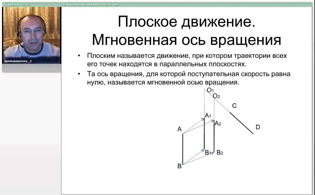
4. Кинематика твердого тела
330
This section introduces the core concepts of rigid body kinematics. A rigid body is defined as a collection of material points with constant distances between them. The position of a rigid body in space is uniquely determined by three non-collinear points, characterized by nine coordinates with three constraint equations, resulting in six degrees of freedom. The general formula for degrees of freedom is DOF = (number of particles × 3) - (number of constraints). Three types of motion are distinguished: translational motion where all points move identically, rotational motion where two points remain stationary defining the axis of rotation, and planar motion where all trajectories lie in parallel planes.
Click to watch →

Degrees of Freedom of Robots Explained | Fundamentals of Robotics
20.4K
Degrees of freedom (DOF) in robotics refers to the dimension of the configuration space, representing the minimum number of real numbers needed to describe a robot's position. A rigid body in 3D space has six DOF: three translational (x, y, z axes) and three rotational (around x, y, z axes). This can be mathematically derived by considering three points on the body—the first has three DOF, the second lies on a sphere (two DOF), and the third lies on a circle (one DOF). In 2D plane, a rigid body has three DOF: two translational and one rotational. When confined to a plane, three constraints are imposed (no z-motion, no roll or pitch), reducing DOF from six to three.
Click to watch →

The motion of rigid bodies - translation, rotation and special cases
878
A rigid body is an idealized model where points maintain constant relative positions. Position determination requires three non-collinear points, yielding nine data but only six independent degrees of freedom due to fixed inter-point distances. Euler angles (ψ, θ, φ) describe orientation through successive rotations about coordinate axes. Translation involves all points moving along parallel paths with identical velocities, requiring only one point for description. Rotation keeps axis points stationary while others trace perpendicular arcs, necessitating both position and orientation data.
Click to watch →

Kinematics of Rigid Body Motion-2
296
A rigid body is a system of particles where distances between any two particles remain constant. It has 6 degrees of freedom: 3 translational (along x, y, z axes) and 3 rotational (about x, y, z axes). To describe rigid body motion, two coordinate systems are used: a body coordinate system attached to the body (typically with origin at center of mass) and a space coordinate system fixed in space. The body coordinate system moves with the body while the space coordinate system remains stationary.
Click to watch →
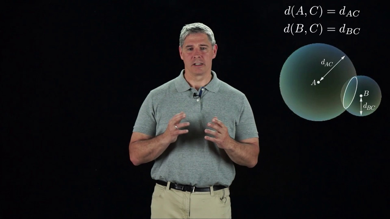
Modern Robotics, Chapter 2.1: Degrees of Freedom of a Rigid Body
96.9K
A rigid body in three-dimensional space has six degrees of freedom, consisting of three linear degrees of freedom (x, y, z position) and three angular degrees of freedom (roll, pitch, yaw), which can be determined by choosing three points on the body and accounting for the geometric constraints that maintain the body's rigidity: three coordinates for the first point with no constraints, two additional coordinates for the second point constrained to a sphere around the first point, and one coordinate for the third point constrained to a circle at the intersection of spheres around the first two points.
Click to watch →
Deep Dive
Basic material science principles, specifically the behavior of elastomers, polymers, and viscoelastic materials.

What Are Elastomers?
27.9K
Elastomers are viscoelastic polymer materials that exhibit both elastic and viscous properties, allowing them to stretch significantly and return to their original shape without permanent deformation; they achieve this unique flexibility through minimal cross-linking between polymer chains, distinguishing them from other polymers like thermoplastics which lack significant cross-linking and thermosets which have extensive cross-linking that limits mobility.
Click to watch →

viscoelasticidad
9.4K
Viscoelasticity is a material behavior combining elastic and viscous properties. Elastic solids deform and recover (Hooke's Law), while viscous fluids deform without recovery (Newton's Law). Viscoelastic materials recover only part of deformation, with behavior shifting from elastic at low temperatures to viscous at high temperatures. Four key properties reveal viscoelasticity: creep (continuous deformation under constant load), stress relaxation (decreasing stress under constant deformation), cyclic loading (hysteresis loop indicating energy dissipation), and strain rate dependence. Common examples include memory foam, gels, gelatin, and silicone putty. NASA developed flexible polyurethane viscoelastic materials for pressure relief applications.
Click to watch →

Lecture 26: Introduction to Viscoelasticity
2.4K
Viscoelastic materials exhibit both elastic and viscous responses simultaneously. Elastic materials follow Hooke's law (ε = σ/E) while viscous materials follow Newton's law (dε/dt = σ/η). True viscoelastic materials show instantaneous deformation followed by continuous deformation under load, with partial recovery upon unloading and some permanent set. This behavior is typical of polymers like bitumen. Understanding these fundamental principles enables proper characterization through transient experiments (creep and relaxation tests) and dynamic oscillatory methods.
Click to watch →

Elastic, Unelastic Viscoelastic Behaviours of Material// Material Science
5K
This video introduces fundamental concepts in material science, focusing on three key categories of material behavior under stress: elastic, unelastic (plastic), and viscoelastic. Elastic materials return to their original shape after deformation when the applied force is removed, demonstrating reversible deformation. Unelastic or plastic materials undergo permanent deformation where the material does not fully recover its original dimensions. Viscoelastic materials exhibit time-dependent behavior, showing characteristics of both elasticity and viscosity—deforming gradually under constant load and recovering slowly when the load is removed. Understanding these behaviors is essential for selecting appropriate materials in engineering applications, as each category responds differently to mechanical stress and environmental conditions.
Click to watch →
Elastic, Anelastic & Viscoelastic Behavior | Material Science | ME303 Explained EP-3
186
Viscoelastic behavior represents a combination of elastic and viscous properties in materials under applied stress. A viscoelastic material exhibits both instantaneous elastic response and time-dependent viscous flow, meaning it partially returns to its original shape but also undergoes permanent deformation over time. This behavior combines solid-like elastic and liquid-like viscous properties. The response to stress depends on loading rate: faster loading results in more elastic behavior, while slower loading leads to more viscous behavior. Key phenomena include creep (gradual deformation under constant stress) and stress relaxation (gradual decrease in stress under constant strain). These materials can be modeled using Maxwell, Kelvin-Voigt, and standard linear models. Common examples include polymers, biological tissues, and glass. A practical application is memory foam mattresses, which gradually recover their shape after deformation.
Click to watch →
Deep Dive
Introductory control systems theory, including open-loop and closed-loop feedback mechanisms.
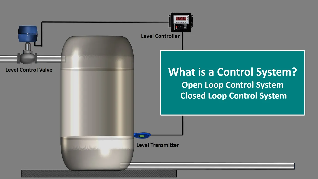
What is Control System.Control System Engineering.Open Loop and Closed Loop Control System.Explained
48.1K
A control system is an arrangement of components that performs a specific task by transforming input through a process to produce output; it can be classified into open loop systems (which operate without feedback and assume output meets requirements) or closed loop systems (which use feedback to automatically adjust and maintain desired output).
Click to watch →
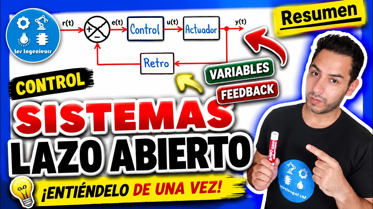
✅INTRODUCCIÓN SISTEMAS de CONTROL | LO QUE DEBES SABER💯| Curso TEORÍA del CONTROL
156.5K
Control systems are classified as open-loop or closed-loop based on feedback presence. Open-loop systems follow a sequential chain: Controller → Amplifier → Actuator → Plant, with no feedback path. The timer-controlled lamp example demonstrates this: a 555 timer generates timing pulses, a transistor amplifies the signal, and a relay activates the lamp for a predetermined duration. These systems are simple and cost-effective but cannot compensate for disturbances or errors once they occur. Closed-loop systems add a feedback path: Plant output connects back to the summing point via Sensor → Transducer → Signal Conditioning. The error signal (reference minus actual) drives the controller. Robotic manipulators demonstrate closed-loop principles with continuous sensing and comparison. Closed-loop systems continuously monitor output and adjust control actions in real-time, providing inherent immunity to disturbances and ensuring accurate tracking of reference inputs.
Click to watch →

FUNDAMENTAL OF CONTROL SYSTEM // ER. / MRS. SUSHREE SANGITA DASH
857
Control systems are combinations of physical components arranged to produce proper output for a given reference input, and they are classified into two main types: Open Loop Control Systems, where the control action depends only on the input signal and not on the output, and Closed Loop Control Systems, where the control action depends on both the input signal and the output through a feedback path. Feedback is further divided into Positive Feedback, where the feedback signal is added to the input signal, and Negative Feedback, where the feedback signal is subtracted from the input signal.
Click to watch →

Control systems | Open loop and Closed Loop | Introduction | Lec-01
13.3K
A control system is a type of system that produces desired output by controlling its input, distinguishing it from a normal system which simply transforms input to output; control systems are categorized into two main types: open loop control systems, which operate without feedback and directly generate control signals to produce output, and closed loop control systems, which incorporate a feedback path that measures the actual output, compares it with the desired input at a mixer to generate an error signal, and automatically adjusts the control signal to achieve the desired output.
Click to watch →

Lec-01 || Introduction of Control System
210
An Open Loop Control System is a system without feedback where the output does not affect the control action. A Closed Loop Control System is a system with feedback where the output is measured and fed back to compare with the desired input, allowing the system to correct errors automatically. Negative Feedback Systems are the most commonly used feedback configuration, where the feedback signal is subtracted from the input signal to reduce error and improve stability.
Click to watch →
Deep Dive
Familiarity with Computer-Aided Design (CAD) software and basic 3D modeling workflows.

Zero to Hero | Mechanical Design -1
388
CAD (Computer-Aided Design) is the digital equivalent of manual drawing, enabling precise dimension specification and manufacturing preparation. Two fundamental manufacturing types exist: additive manufacturing (3D printing) builds objects layer by layer, while subtractive manufacturing (CNC machining) removes material from solid blocks. Popular CAD software includes Fusion 360 (free for students), SolidWorks, and FreeCAD. Mouse navigation controls include scroll wheel for zoom/rotation, middle button for rotation, and right button for panning. Standard views include Home (isometric), Front, Right, and Top views. Before 3D modeling, designers must master 2D sketching, selecting appropriate sketch planes (Front, Right, Top) based on design perspective. Primitive shapes (cubes, cylinders, triangles) serve as foundational building blocks. The origin point provides a reference coordinate system. Dimensioning uses the dimension tool to specify exact measurements. Converting 2D sketches to 3D requires understanding extrusion (extending profiles along an axis) and revolve (rotating sketches around an axis). The fillet tool creates rounded edges for manufacturability. Design flexibility is key—multiple approaches can achieve identical outcomes as long as dimensions are correct.
Click to watch →

Solidworks Basic Tutorial Part 1(overview and part)
182
SolidWorks is a Computer-Aided Design (CAD) software that enables users to design equipment, perform simulations, and conduct strength analysis. The software provides three default templates: Part (3D single or multi-body parts), Assembly (combining multiple parts with mechanisms and motion studies), and Drawing (production representations). The Novice system restricts users to default templates, while Advanced mode allows custom template creation. The 3D modeling workflow involves: (1) Creating 2D sketches using basic geometric shapes on reference planes, (2) Defining dimensions and establishing geometric relationships between elements (blue indicates undefined, black indicates fully defined), (3) Converting 2D sketches to 3D objects using Extrude Base (adds material) or Extruded Cut (removes material), (4) Using Hole Wizard for uniform holes or Extruded Cut for irregular shapes. This foundational knowledge prepares learners for the structured tutorial series covering basic to professional CAD skills.
Click to watch →
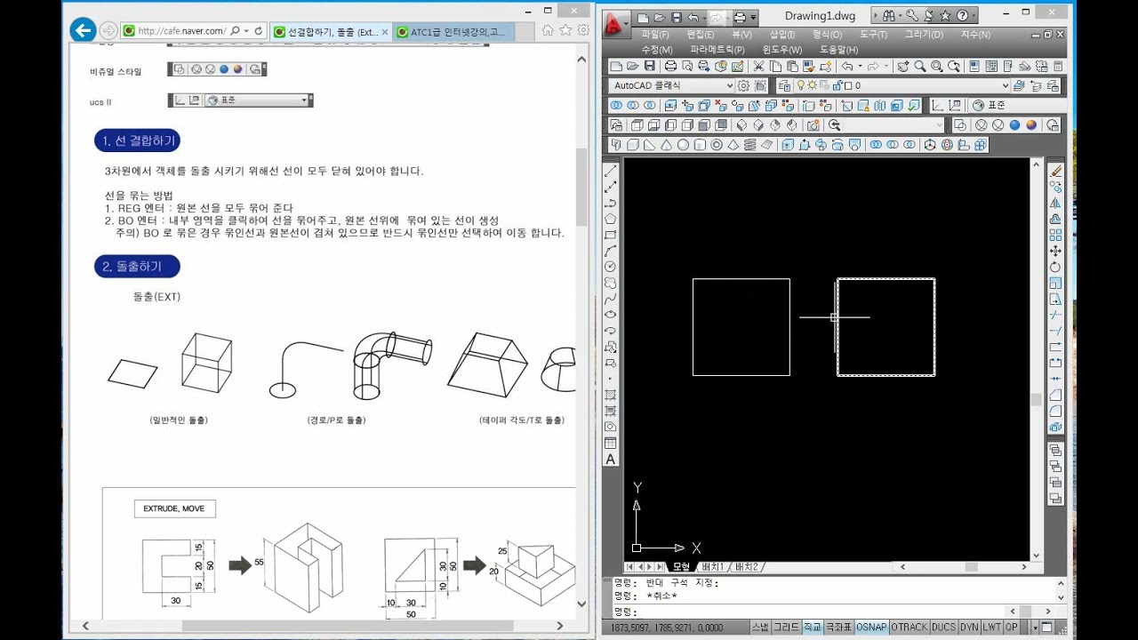
2-2 CAD실무능력평가 1급 AutoCAD / 3D 기본 명령어
181
This comprehensive lesson covers the complete workflow for 3D CAD modeling. First, master 2D CAD commands as 3D builds upon 2D skills. Extract five essential icons: Solid Editing, Surface Editing, Modeling, Visual Styles, and View. Learn two methods for joining broken lines: JOIN for closed shapes and UNION for partially connected objects. Switch to South-East view for 3D operations. Use EXTRUDE command to create 3D objects from joined 2D profiles, specifying height. Understand the difference between Solid Extrusion (filled objects) and Surface Extrusion (hollow/mesh-like). Switch to Visual Styles to see actual 3D forms. This foundational workflow prepares students for advanced operations like union, difference, and intersection.
Click to watch →

7. SINIF TEKNOLOJİ VE TASARIM - Bilgisayar Destekli Tasarım
8.6K
CAD (Computer-Aided Design) is the use of computer software for creating, modifying, and optimizing designs. Major CAD programs include Autodesk 3ds Max (popular 3D modeling and animation), Blender (open-source 3D modeling with game engine), AutoCAD (30+ years of development, 2D/3D capabilities), Autodesk Maya (3D design for advertising, gaming, film), SolidWorks (3D modeling and optimization for engineering sectors), CATIA (transportation design for automotive, aerospace, shipbuilding), and SketchUp (accessible 3D modeling for architects and designers). Each program serves specific industry needs, from professional engineering to educational purposes.
Click to watch →

Reka Cipta Tingkatan 5 Bab 1 LukisanTerbantu Komputer Revisi Nota
3K
Computer-Aided Design (CAD) is a method for creating designs of products or objects using computer software. CAD enables designers to create both 2D and 3D representations. The technology is widely used in mechanical engineering, architecture, civil engineering, and graphic design. Key CAD software includes AutoCAD for product design and architectural drawings, SolidWorks for 3D modeling, and Adobe Illustrator for graphic design and logo creation. 3D modeling allows designers to create complex objects with realistic appearances. 3D drawing represents objects using length, width, and height measurements across X, Y, and Z axes. CAD software provides various drawing tools for creating circles, curved lines, text labels, hexagons, rectangles, and circles, along with dimensioning tools for adding measurements.
Click to watch →
Deep Dive
Elementary fluid dynamics and pneumatics, as many soft actuators rely on fluidic pressure.

EML Webinar by Prof. Rob Shepherd, Cornell University on 16 Sept. 2020
2.9K
Fluidic soft actuators are limited by mass transport requirements - moving fluid into chambers to cause actuation, typically achieving 2-10 Hz. This is slower than field-driven actuators (dielectric elastomers) which respond almost instantaneously. The smaller the actuator, the more exacerbated this problem becomes due to pressure drop. Pneumatic actuators face integration challenges: each actuator requires its own pipeline, creating serial rather than parallel connections. The energy medium is related to energy rate - fewer molecules in smaller pipelines means less power. Solutions include multiplexing techniques (like Quake valves from microfluidics) and distributed computation throughout the robot.
Click to watch →

Hydraulics and Pneumatics|Introduction|Objective Question|By-Er.Raghav awasthi
4.1K
Hydraulics and pneumatics is a polytechnic subject that studies the behavior of fluids (liquids and gases) in engineering systems, covering key concepts such as fluid classification based on viscosity (Newtonian vs non-Newtonian), density (mass per unit volume, e.g., water = 1000 kg/m³, mercury = 13500 kg/m³), specific weight, viscosity (resistance to flow), surface tension, and adhesion/cohesion forces that govern fluid behavior in mechanical systems.
Click to watch →

16 LEZIONE DIMENSIONAMENTO ATTUATORI E ANALISI CIRCUITI PNEUMATICI ACCENNI DI FLUIDODINAMICA
905
This video covers the design and analysis of pneumatic actuators, explaining how to calculate force from pressure and area (F = P × A), determine acceleration using Newton's second law, and understand minimum pressure requirements for system movement. It also introduces Bernoulli's principle and the continuity equation for fluid dynamics, explaining how pressure and velocity are related in fluid systems, and discusses pressure losses in fluid conduits due to friction and turbulence.
Click to watch →

2-way FSI Fluid-Structure interaction of Soft Pneumatic Actuators / Ansys FEM Soft Robots Simulation
4.1K
Traditional soft actuator research focuses exclusively on structural mechanics, failing to capture the true physics of pneumatic actuation. When pressurized, fluid interactions within actuator cavities generate forces that deform the structure, yet these interactions remain poorly understood. Most published works lack detailed investigation of internal fluid dynamics, leaving critical questions unanswered about what actually happens inside pneumatic networks during operation. This knowledge gap prevents standardization of soft actuator development and leads to unpredictable test results. Addressing this requires fundamentally new simulation approaches that couple fluid dynamics with structural mechanics to reveal the complete picture of actuation physics.
Click to watch →
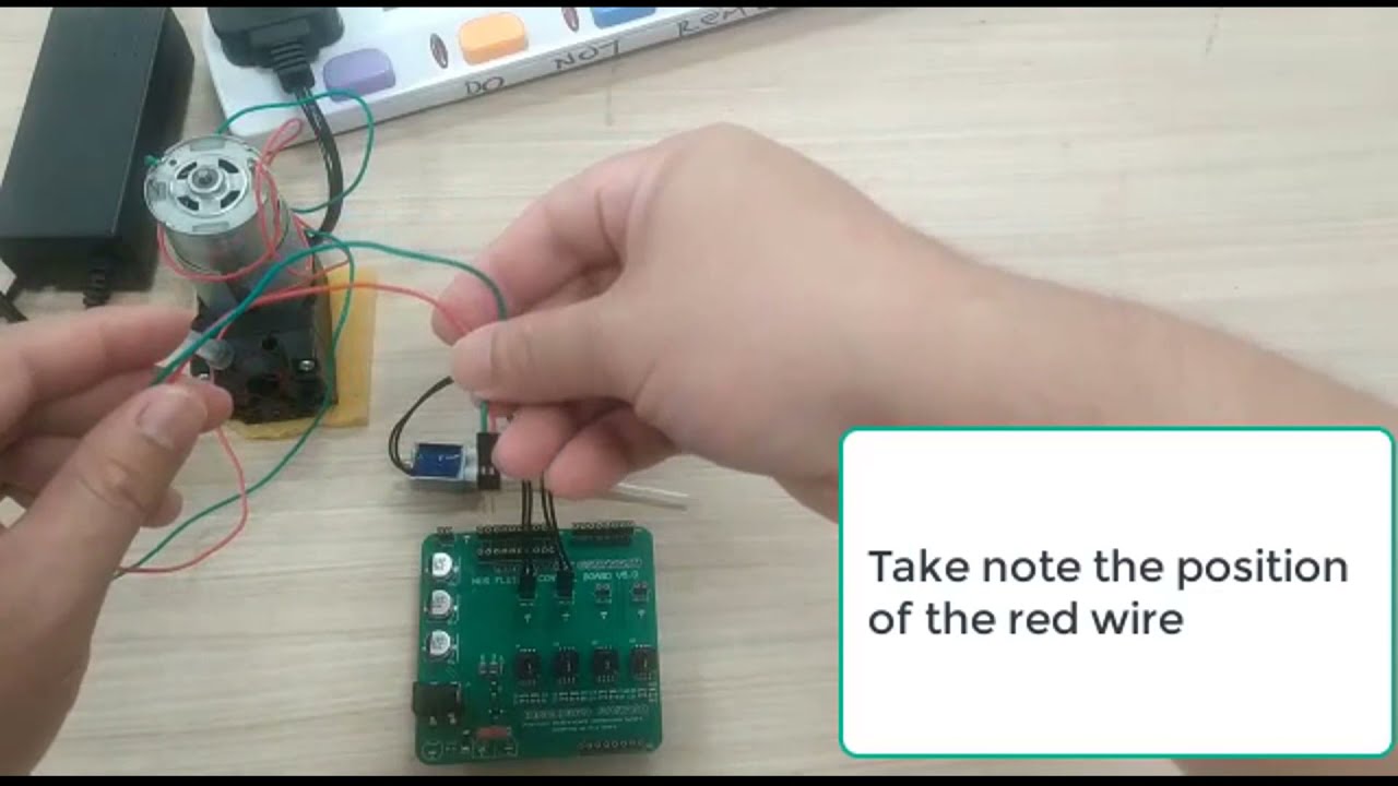
Soft Robotics Fluidic Control Board V2
1.4K
A fluidic control board can be programmed using Arduino to control the flexion and extension of a soft tip actuator by managing pressure valves through specific digital pin configurations (pins 3, 9, and 5), where pins 3 and 9 are initialized as outputs and turned off while pin 5 is turned on to activate the actuator movement.
Click to watch →
Prerequisite Knowledge
- Concept 01Fundamental concepts of traditional rigid-body robotics, including kinematics and degrees of freedom.
- Concept 02Basic material science principles, specifically the behavior of elastomers, polymers, and viscoelastic materials.
- Concept 03Introductory control systems theory, including open-loop and closed-loop feedback mechanisms.
- Concept 04Familiarity with Computer-Aided Design (CAD) software and basic 3D modeling workflows.
- Concept 05Elementary fluid dynamics and pneumatics, as many soft actuators rely on fluidic pressure.
Subsequent Learning
- Step 01Advanced fabrication techniques such as multi-material 3D printing and sacrificial molding for complex soft structures.
- Step 02Non-linear modeling and advanced control strategies, including machine learning-based control for soft manipulators.
- Step 03Integration of flexible, stretchable sensors for proprioception and tactile feedback in soft robots.
- Step 04Biomedical applications of soft robotics, such as wearable assistive devices, exosuits, and minimally invasive surgical tools.
- Step 05Bio-inspired soft robotic design, translating biological locomotion (e.g., peristalsis or undulation) into engineered systems.
Design and Build
Model and Control
Design and Build
0:01Playing Section
- 1
Provides CAD files, printing guides, and casting tutorials.
- 2
Includes case studies for inspiration and design principles.
- 3
Details material lists and supplier links for construction.
Traditional Rigid Robotics and the Limits of Compliance
While soft robotics offers flexibility and safety, traditional rigid robotics presents a necessary counterpoint focused on precision, speed, and force transmission. Soft robots, due to their compliant nature and infinite degrees of freedom, are notoriously difficult to model, control, and sense accurately. Traditional rigid-bodied robots rely on established, mathematically rigorous kinematics and dynamics, enabling sub-millimeter precision and high-load capacities that soft materials cannot match. Critics argue that compliance introduces unpredictability and energy inefficiency, making soft robotics unsuitable for tasks requiring high repeatability, structural stability, or rapid actuation. Consequently, many researchers advocate for rigid or hybrid systems over purely soft designs.
Deep Dive
Advanced fabrication techniques such as multi-material 3D printing and sacrificial molding for complex soft structures.
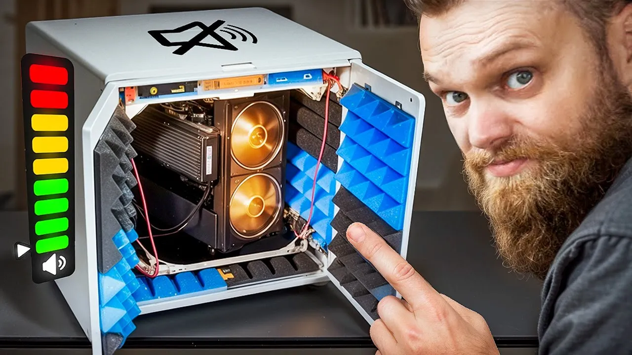
This over-engineered IKEA hack got out of hand!
331.8K
Advanced fabrication combines multiple materials (ABS and TPU) that bond effectively for creating complex components. This includes designing suspension systems with rigid and flexible sections, creating precision cutting tools for foam panels, and converting 3D designs to laser-cut files through DXF to SVG workflows. The process demonstrates how multi-material printing enables solutions that would be difficult or impossible with single-material approaches.
Click to watch →

FLSun V400 Review - Tall - Fast - Klipper
29.3K
The V400 demonstrates advanced printing capabilities including print-in-place hinges on a toolbox (3h 14m), spiral vase mode for a trashcan (2h 23m), and multi-material printing. A bottle opener printed in 20 minutes with 6 walls and 50% infill for strength. A herringbone planetary gear printed in 45 minutes with moving parts that function correctly. A squeeze fan was printed with a body in PETG, gears in copper silk PLA, and fan blades in TPU for safety. Silk PLA showed poor layer adhesion on the gear connecting to blades, requiring reprint in regular PLA.
Click to watch →
3D Printing Multi Material? Turn this setting on.
47K
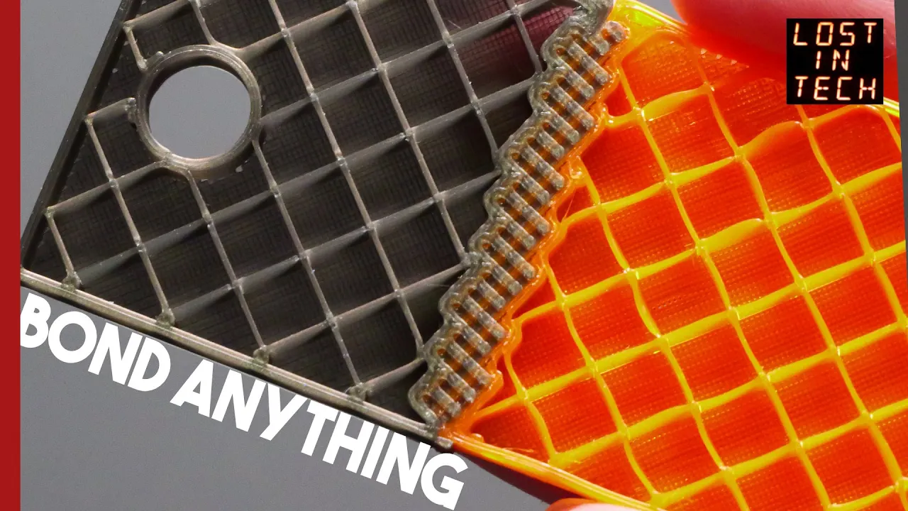
Multi-Material Interlocking (ITIL) is a slicing feature that creates mechanically interlocked structures between incompatible materials (like PLA and PETG) by generating repeating unit cells along the interface boundary, which creates topologically linked chain-mail style connections that are significantly stronger than simple overlapping layers, solving the common problem of weak multimaterial prints.
Click to watch →
Alonso Martinez's 3D-Printed Animated Robots!
281.4K
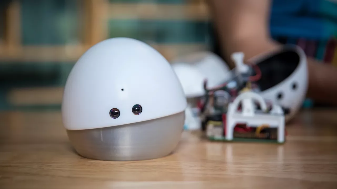
Creating soft, flexible parts from 3D printed molds involves injection molding silicone rubber. The process uses a two-part mold system bolted together, with silicone injected using a syringe. After curing for approximately one hour, the result is a super-stretchy, flexible part. This technique allows creation of organic shapes that would be difficult to produce directly through 3D printing alone.
Click to watch →

PitStop 3 multi-material 3D printer in-depth design. 10+ materials at once
73.4K
Multi-material 3D printing enables printing with multiple colors or materials without the waste associated with single-extruder color changes. A tool changer with multiple hotends can host at least 10 hotends, allowing printing with 10 materials simultaneously. The system uses a revolving arm that parks hotends in free spaces and loads preheated hotends for continued printing. Hotends connect via pogo connectors rated for 9 amps with 1 million mating cycles. Kinematic mounting provides micron precision. NFC tags store hotend information for verification. Two main approaches exist: single hotend with changing filament (creates mixed colors and requires purge blocks) and multiple hotends with independent extruders (avoids color mixing but risks oozing). The design philosophy prioritizes reliability, user-friendliness, and achieving better print quality than existing printers without requiring extensive configuration or tuning.
Click to watch →
Deep Dive
Non-linear modeling and advanced control strategies, including machine learning-based control for soft manipulators.

SIAM DS21: Michael Banks - Koopman Mode Analysis and Control of a Soft Robotic Arm
244
Building accurate models of soft robots requires collecting diverse training data including both quasi-static movements and aggressive transients. The modeling process involves formulating optimization problems solved via Moore-Penrose pseudoinverses to obtain state transition and input matrices. Critically, monomial observables fail for soft robots due to polynomial tail divergence, while time-delay observables consistently improve model accuracy. Once a linear approximation exists, Linear Quadratic Regulator control can effectively manage highly nonlinear systems, demonstrating how data-driven linearization enables practical control of complex mechanical systems.
Click to watch →

Autonomy Talks - Michael Posa: Multi-contact learning and real-time control
1.1K
An implicit formulation for model learning avoids the fundamental problems of prediction error loss by reformulating the learning problem. Instead of directly comparing predicted states to measured states (creating a stiff optimization landscape), the approach formulates the model as equations with complementary constraints. Turning complementarity constraints into soft penalties reshapes the optimization landscape without changing the true solution. This preserves the true solution while making optimization tractable—the Lipschitz constant no longer depends on dynamics stiffness. Unlike softening dynamics (which changes the solution), this approach reshapes the landscape. This enables learning piecewise affine models with thousands of modes simultaneously. For complex manipulation tasks like tri-fingered cube manipulation (with thousands of possible contact modes), full complexity is unnecessary. The approach involves learning a reduced-order LCS model from data, using it with an NPC controller in a trust-region framework, and iterating between model learning and control. This can dramatically reduce modes (from 100+ to 4) while maintaining almost no performance cost.
Click to watch →

Autonomy Talks - Cosimo Della Santina: Controlling Soft Robots: a (mostly) model-based view
665
Rather than relying solely on first-principles physics-based models, researchers can learn dynamic models directly from data while respecting known structural properties of soft robot dynamics. Neural networks modified for soft robot applications capture essential mathematical structures. Critically, this approach enables theoretical guarantees about closed-loop stability even with imperfect learning. The pipeline combines machine learning flexibility with classical control theory guarantees, representing a promising direction for soft robot control. Similar approaches apply deep learning for compressing high-dimensional dynamics while maintaining structural properties, enabling deployment on real systems with comparable performance to expert-engineered controllers.
Click to watch →

BrIAS Seminars: Hideyuki Sawada
247
Soft robots use soft materials and actuators, unlike rigid robots with fixed geometry. Rigid robots have calculable paths, but soft robots (like human hands) can move flexibly in multiple positions. This flexibility requires machine learning for control since motion cannot be precisely calculated. Research includes 3D printed biomimetic fingers with artificial muscles, tactile displays, waterborne actuators, and insect-like robots. The key advantage is adaptability to human environments, though control is more challenging than rigid systems.
Click to watch →
lec34 Control of a multi-link manipulator
933
Computed torque control (feedback linearization) is a non-linear control scheme for multi-link manipulators that partitions the control input into two parts: a model-based portion using the robot's dynamic equations (mass matrix, Coriolis-centripetal terms, gravity, and friction) and an error-driven portion implementing PD control. By choosing α = M(q) and β = C(q, q̇) + G(q) + F(q), the non-linear dynamics are transformed into n decoupled linear equations τ' = q̈, enabling uniform performance across the entire workspace. Simulation and experimental results demonstrate that even with 10% mass estimation errors and 5% CG location errors, computed torque control significantly outperforms linear PD control, reducing tracking errors from centimeters to millimeters while providing smoother torque profiles.
Click to watch →
Deep Dive
Integration of flexible, stretchable sensors for proprioception and tactile feedback in soft robots.

ORI Anniversary Seminar Series 21-22 - Daniela Rus
110
This section addresses the critical challenge of giving soft robots the ability to sense their own configuration. The speaker describes 3D embedded printing, a method that adds sensors (curvature, inflation, and contact sensors) into silicone molded material while it cures. This creates flexible, elastic sensors that support robot needs. The goal is to create a system where continuous sensors embedded in the robot's body can provide automatic measurements of the robot's configuration—proprioception. The speaker introduces kirigami, a method where sensor response depends on cut patterns, and a data-driven approach using neural networks to associate sensory values with geometric configuration. This creates robots with perceptual skin that also know what configuration they are in, which is essential for control.
Click to watch →

Kaitlyn Becker: Mechanical Programming of Soft Robots via Fabrication-Integrated Design
2.2K
Sensor integration in soft robots requires balancing information richness with fabrication complexity. Starting with few sensors (pressure sensors and photoresistors) provides redundancy for mapping proprioceptive and exteroceptive feedback through signal analysis. Strategic sensor placement can mechanically guide actuator curvature. Acoustic sensing using microphones detects object shape by analyzing how filament contacts change vibration frequencies—identical-weight objects of different spatial densities produce distinguishable signatures. Optical fiber sensors embedded in soft sheets detect deformation and pressure through refractive index differences, with roughened sides providing directional bending sensitivity. These modalities enable progression from purely mechanically programmed behavior toward reflexive responses.
Click to watch →

A bending sensor for soft body proprioception- Presented by Hareesh Godaba for Robosoft 2020
157
This video presents a low-cost bending sensor developed using commercially available braided optical fibers, where roughening the cladding surface increases light scattering and sensitivity to bending without requiring extreme curvatures; the sensor demonstrates high sensitivity to deformation while being relatively insensitive to normal forces (less than 0.03 change ratio at 120N compared to 0.04 for silicon-based sensors at 50-60N), enabling distributed proprioception in soft robotic fingers through simple optical intensity measurements.
Click to watch →

Flexible Multilayer Tactile Sensor on a Soft Robotic Fingertip
150
A flexible, biomimetic multilayer tactile sensor integrated into a soft robotic fingertip can achieve 97.12% texture classification accuracy by neuromorphically encoding sensor outputs to mimic human skin mechanoreceptors, where three sensor layers (Merkel cell-inspired piezoresistive array, Meissner corpuscle-inspired resistive layer, and Pacinian corpuscle-inspired capacitive disc) work together to capture both spatial and temporal tactile information for texture discrimination tasks.
Click to watch →

Highly Flexible Stretchable Sensors
1.1K
Tacterion's Sensorskin technology integrates resistive and capacitive sensing capabilities into a single highly flexible and stretchable silicone polymer sensor, enabling simultaneous detection of pressure, touch, and proximity without requiring physical contact; this breakthrough technology, developed with expertise from the German Aerospace Center, enables applications in robotics, consumer electronics, automotive, and medical fields by allowing sensors to be deployed on curved and deformable surfaces.
Click to watch →
Deep Dive
Biomedical applications of soft robotics, such as wearable assistive devices, exosuits, and minimally invasive surgical tools.

Cecilia Laschi - Soft Robotics: from bioinspiration to biomedical applications
444
Soft robotics enables capabilities impossible with rigid robots: self-healing materials, elongation/shortening, underwater operation, vascular systems, jamming grasping, and complete squashing without damage. Key biomedical applications include soft exosuits for elderly assistance, flexible needles, soft endoscopes with variable stiffness, prosthetic hands, rehabilitation devices, and realistic body simulators like larynx models. Research impact levels range from showing new mechanisms (Level 0) to contributing to general robotics progress (Level 1). Sustainable growth requires contributions applicable beyond soft robotics to broader fields.
Click to watch →

MIT Robotics - Cecilia Laschi - Methods and technologies for new robotics scenarios
3K
Soft robotics offers transformative potential in biomedical fields including artificial organs, assistive devices, prosthetics, soft exoskeletons, and minimally invasive surgical tools. User-centric design methodologies involving clinical observations and stakeholder interviews reveal that transfer tasks (bed-to-sitting, sitting-to-standing, chair-to-wheelchair) represent the greatest need for robotic assistance in elderly care. Research demonstrates that soft robotic arms can achieve high vertical stiffness for payload carrying while maintaining horizontal flexibility. Jamming transition techniques enable precise stiffness control along specific axes, while origami-inspired designs provide reconfigurable mechanical structures.
Click to watch →

Cosa sono i SOFT ROBOT?
1.9K
Soft robotics has transformative applications in biomedicine. The Skiff Flop is a flexible endoscopic surgical robot enabling minimally invasive operations in complex conditions, developed through collaboration between Sant'Anna Institute of Pisa and the Italian Institute of Technology. Soft prosthetics, 3D printed and completely flexible, connect to the forearm using electrodes and can adapt force output for delicate or strong tasks. Hydrogel, a water-based biomaterial, offers exceptional biocompatibility for internal tissue contact, enabling microchirurgia applications. These advances demonstrate how soft robotics can address human needs in ways rigid robots cannot, from surgical precision to adaptive prosthetic functionality.
Click to watch →
Robots That You Cannot See | with Dr. Carmel Majidi and Dr. Mohammad Islam
28.2K
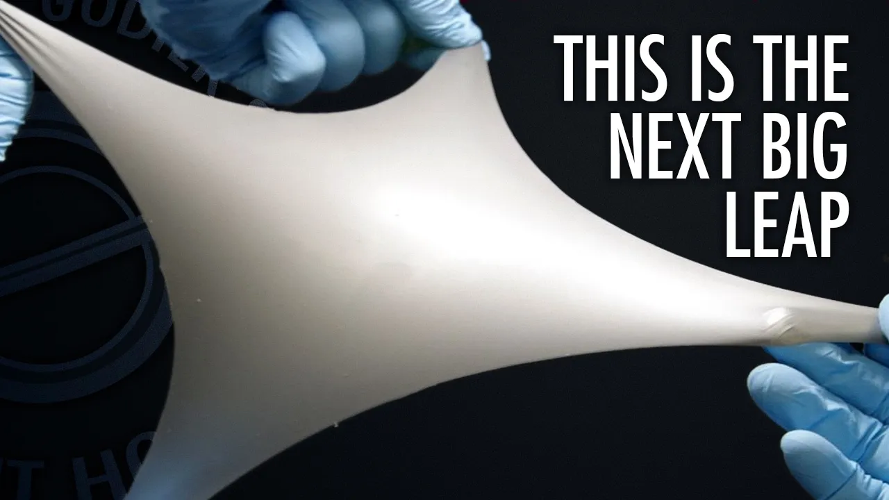
Soft Robotics offers significant advantages in medical applications due to mechanical compliance and biological tissue compatibility. Traditional hard robotics (metals) may trigger immune responses, be too bulky, or lack flexibility. Applications include physiological monitoring sensors that adhere to skin like stickers, surgical soft robotic systems for internal operations, and wearable devices for motor assistance benefiting stroke patients and workers in strenuous environments. Soft robotics enables adjustable casts that can be reshaped for different body parts and reused rather than discarded. The field intersects with biohybrid engineering, combining synthetic soft materials with actual biological tissue to enable self-repairing and adaptive implants like hip replacements that can repair themselves and last longer.
Click to watch →
Flexible Soft Robots: Revolutionizing Surgery and Medicine | Giada Gerboni, TED
222.7K
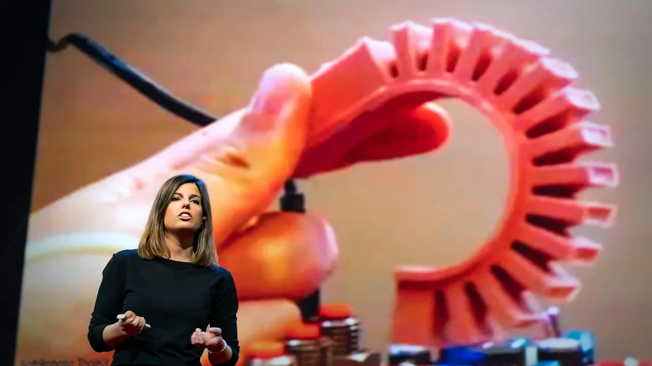
Soft robotics offers significant advantages in medical applications, particularly minimally invasive surgery. Traditional endoscopes use rigid instruments that must enter the body through small holes and interact with delicate structures in uncertain environments. Soft camera robots can bend in every direction and elongate, allowing surgeons to view surgical fields from multiple angles without worrying about what surrounding tissues are touched. This flexibility improves safety and visualization during procedures.
Click to watch →
Deep Dive
Bio-inspired soft robotic design, translating biological locomotion (e.g., peristalsis or undulation) into engineered systems.
![Maryland Robotics Center Seminar, January 31, 2025: Markus P. Nemitz [REUPLOAD]](https://i.ytimg.com/vi/g1aHjIuysYI/maxresdefault.jpg)
Maryland Robotics Center Seminar, January 31, 2025: Markus P. Nemitz [REUPLOAD]
190
Soft robots can be designed by first identifying a legged animal with desirable locomotion characteristics for a specific environment and speed, then analyzing its foot trajectory. Closed-loop trajectories (where the foot returns to its starting position) are characteristic of efficient legged locomotion in animals including humans, unlike open-loop trajectories of worms. This biological inspiration guides the synthesis of mechanical mechanisms that can be translated into soft robots through multimaterial 3D printing.
Click to watch →

Science Slam 2024
149
Soft robotics differs from traditional rigid robotics by using flexible materials that can adapt their shape to interact with objects. By cutting materials like EVA foam into specific geometric patterns (such as inverted honeycomb cells), designers can create structures that exhibit out-of-plane movements similar to biological systems. This bio-inspired approach merges material properties, shape, and behavior into unified systems capable of complex tasks like gripping objects of various shapes and sizes.
Click to watch →
Cecilia Laschi: TO CONTROL, OR NOT TO CONTROL- THAT IS THE QUESTION FOR SOFT ROBOTS WITH EI
141
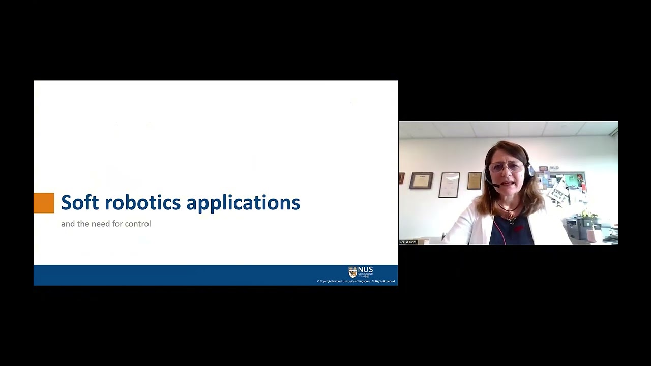
Translating biological principles into functional soft robotic systems requires understanding both morphological features and control strategies. The octopus demonstrates sophisticated locomotion through bending movements that reduce water drag, achieved with only three neural parameters controlling a highly compliant body. Researchers have developed modeling frameworks to simulate muscle activations, identifying which muscles to activate and when to replicate biological movements. Key design principles include anisotropic stiffness distribution, where proximal body parts remain stiff while distal tips remain passive, allowing environmental forces to assist movement. Additionally, many natural structures—including octopus arms, elephant trunks, and plant structures—follow logarithmic spiraling geometries that enable efficient force distribution. By replicating these morphological principles in soft robotic prototypes, engineers can achieve movement patterns similar to biological structures despite having completely different internal architectures, demonstrating how form follows function in nature-inspired design.
Click to watch →
Soft autonomous earthworm robot at MIT
848.9K
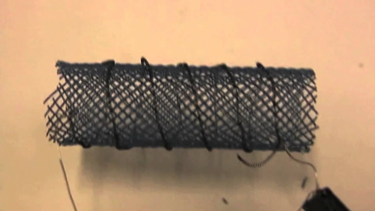
Researchers at MIT, Harvard University, and Seoul National University have developed a soft autonomous robot that moves via peristalsis, similar to earthworms, by contracting segments of its body using nickel-titanium shape memory alloy wires wound around a mesh tube; this design enables the robot to navigate rough terrain and squeeze through tight spaces while demonstrating remarkable durability against physical impacts.
Click to watch →
Bio-Inspired Snake Robot Locomotion Explained by Computerphile
118.2K
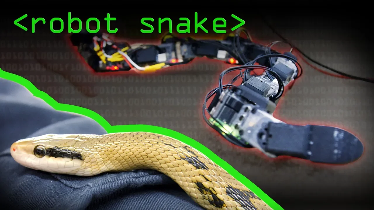
Snake-like robots can replicate four primary locomotion modes—sidewinding (using two sine waves for desert sand movement), lateral undulation (single wave for typical slithering), concertina (for tunnel navigation), and rectilinear (still under development)—by implementing simple mathematical wave patterns on servo motors, though current robots remain tethered due to high energy consumption and lack sophisticated skin actuators for full biomimicry.
Click to watch →
Design and Build
Model and Control
Design and Build
0:01- 1
Provides CAD files, printing guides, and casting tutorials.
- 2
Includes case studies for inspiration and design principles.
- 3
Details material lists and supplier links for construction.
Traditional Rigid Robotics and the Limits of Compliance
While soft robotics offers flexibility and safety, traditional rigid robotics presents a necessary counterpoint focused on precision, speed, and force transmission. Soft robots, due to their compliant nature and infinite degrees of freedom, are notoriously difficult to model, control, and sense accurately. Traditional rigid-bodied robots rely on established, mathematically rigorous kinematics and dynamics, enabling sub-millimeter precision and high-load capacities that soft materials cannot match. Critics argue that compliance introduces unpredictability and energy inefficiency, making soft robotics unsuitable for tasks requiring high repeatability, structural stability, or rapid actuation. Consequently, many researchers advocate for rigid or hybrid systems over purely soft designs.
Fundamental concepts of traditional rigid-body robotics, including kinematics and degrees of freedom.
Basic material science principles, specifically the behavior of elastomers, polymers, and viscoelastic materials.
Introductory control systems theory, including open-loop and closed-loop feedback mechanisms.
Familiarity with Computer-Aided Design (CAD) software and basic 3D modeling workflows.
Elementary fluid dynamics and pneumatics, as many soft actuators rely on fluidic pressure.
Advanced fabrication techniques such as multi-material 3D printing and sacrificial molding for complex soft structures.
Non-linear modeling and advanced control strategies, including machine learning-based control for soft manipulators.
Integration of flexible, stretchable sensors for proprioception and tactile feedback in soft robots.
Biomedical applications of soft robotics, such as wearable assistive devices, exosuits, and minimally invasive surgical tools.
Bio-inspired soft robotic design, translating biological locomotion (e.g., peristalsis or undulation) into engineered systems.
51.8K views721likes3:04@harvardOriginal Release: 2014-09-19
the Soft Robotics toolkit is a website that contains all of the information required to design build and operate soft robots Soft Robotics is a growing field which combines classical principles of robot design with the study of soft flexible materials soft robots consist of lowcost simple components that can achieve complex motions when inflated for example when we pressurize the air inside this actuator it bends components like this can be mechanically program to achieve motions for specific applications like this glove to assist with grasping tasks or this cardiac simulator which mimics the motion of the heart the Soft Robotics tool kit is a collection of resources to support users in developing these types of Novel devices soft robots can be built by casting silicone rubbers in 3D printed molds the toolkit contains mold CAD files that can be downloaded and modified users who want to design their own molds can follow the guidelines and step-by-step tutorials provided on the website case studies describing other people's designs can be used as inspiration once a mold has been designed it can be printed with a 3D printer the toolkit's detailed multimedia instructions explain the casting and Fabrication process the website lists all of the parts required for building soft robots as well as links to suggested suppliers predicting the behavior of soft robotic devices is difficult the toolkit contains tutorials and case studies on modeling and characterizing soft components to help users optimize their own designs much of the hardware used to operate soft robots is transferable between one device and another so the toolkit includes details of an open-source control board based on readily available parts that can be used for a wide variety of applications the website also contains example source code to get users started with operating and controlling their soft robots the board can be built as described on the website or can be modified to suit the needs of particular projects Soft Robotics is a growing field and the Soft Robotics toolkit provides a way for students designers and researchers of all levels to learn how to design model build and test their own Soft Robotics components and to use these components to create novel devices for exciting applications
Up Next

9:47
How to Start with Arduino: Complete Beginner's Guide to the IDE
@FlamethrowerYT
2.5K views•2025-07-26

12:54
Triumph of Orthodoxy Icon: Byzantine Art & History Explained
@BenCallan
2.1K views•2024-08-06
68:44
The Science of New African Cuisine with Selassie Atadika
@harvard
41.7K views•2020-01-06

1:42
Game of Thrones Opening Credits: A Cinematic Analysis
@gameofthrones
46.3M views•2011-04-18
Related Study Plans & Knowledge Roadmaps
Structured learning paths in General & Interdisciplinary Studies
general-studies
Elevator Engineering: History, Physics & Cities
01From Hoists to Safety Brakes: The Dawn of Vertical Lift
02Hydraulic vs. Traction: The Engineering Physics of Elevators
03Modern Speed, Safety, and Algorithms
+ 2 more learning modules
12h5 modules
Explore Roadmap
general-studies
Rubber: Material Science, History & Geopolitics
01Origins of Natural Rubber & Mesoamerican History
02The Chemistry of Natural Rubber & Vulcanization
03The Geopolitics of the Rubber Boom & Colonization
+ 2 more learning modules
12h5 modules
Explore Roadmap
general-studies
Containerization: Evolution, Logistics & Trade
01Ancient Trade & Bulk Cargo: Amphorae to Barrels
02The Industrial Revolution & Cardboard Packaging
03The Containerization Revolution: Malcom McLean
+ 2 more learning modules
12h5 modules
Explore Roadmap
general-studies
Textile Tech: Evolution, Labor & Global Impact
01Pre-Industrial Textiles: Handloom & Cottage Industry
02Mechanization: The Spinning Jenny to the Power Loom
03The Factory System & Global Labor Transformation
+ 2 more learning modules
10h5 modules
Explore Roadmap