



![[Linear Algebra] Matrices and Transformations](https://i.ytimg.com/vi_webp/LspUdM6IPYk/maxresdefault.webp)


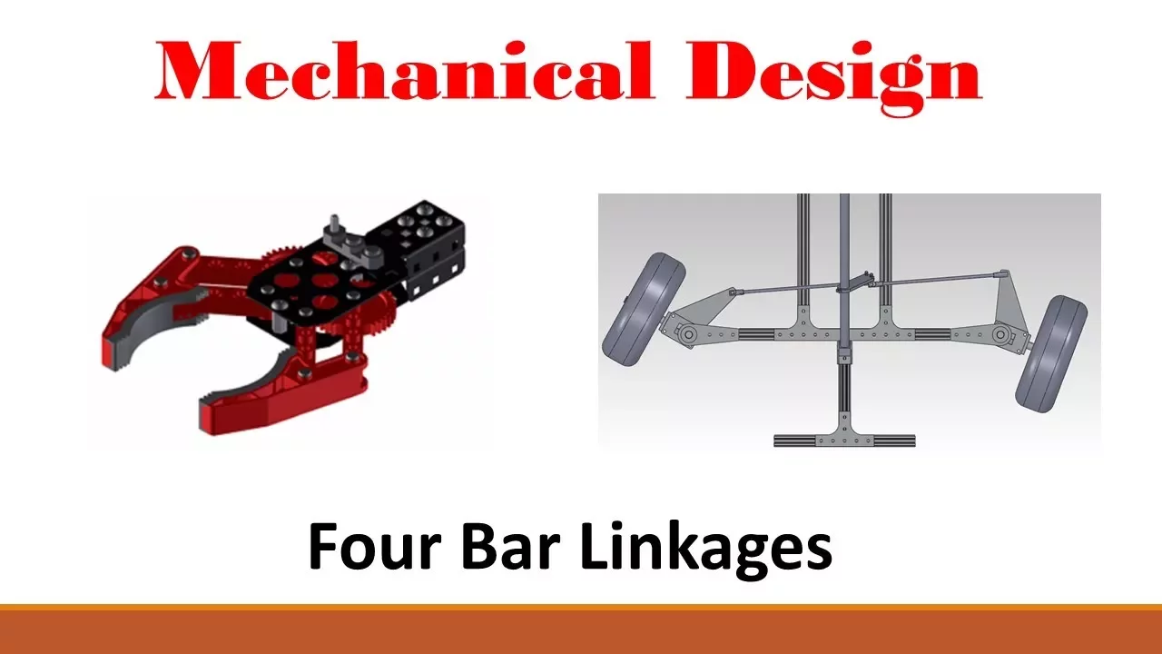




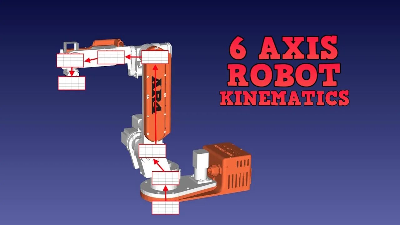


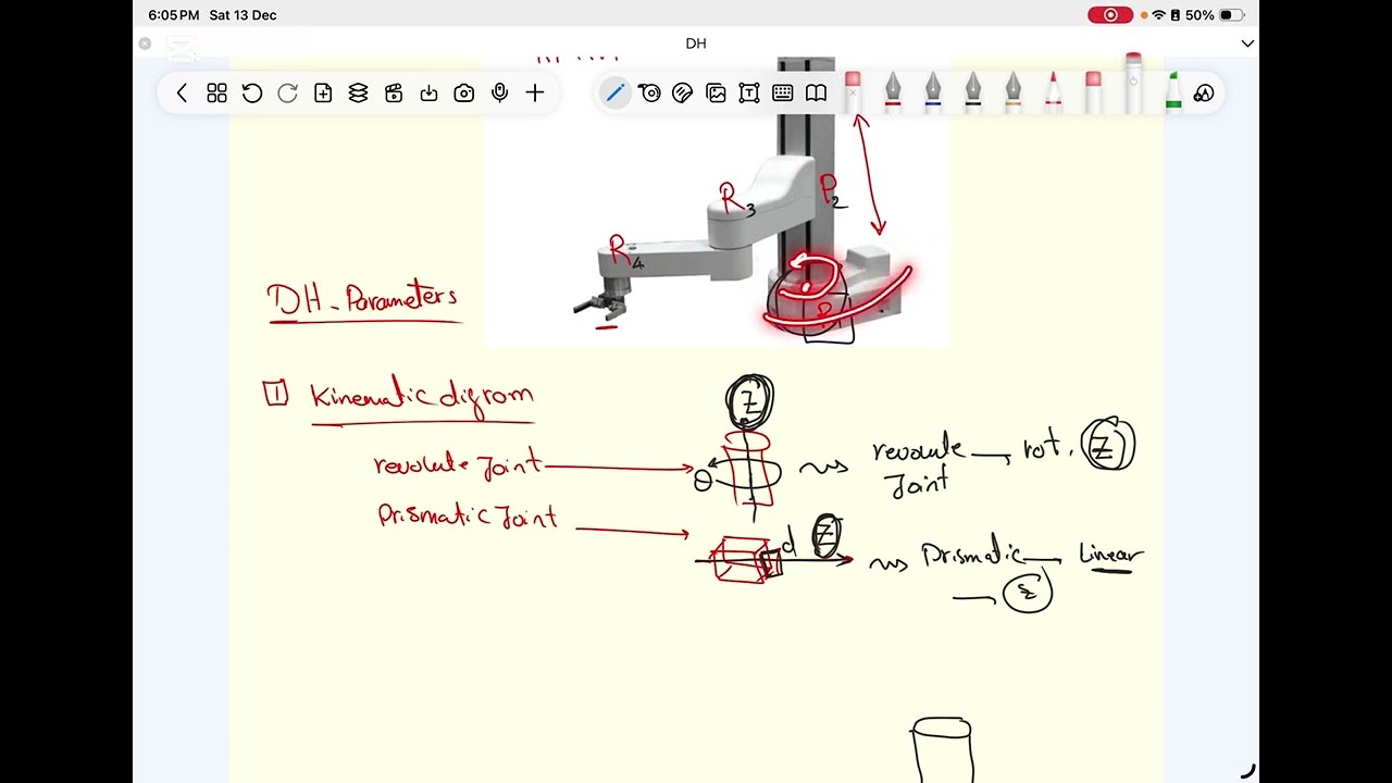
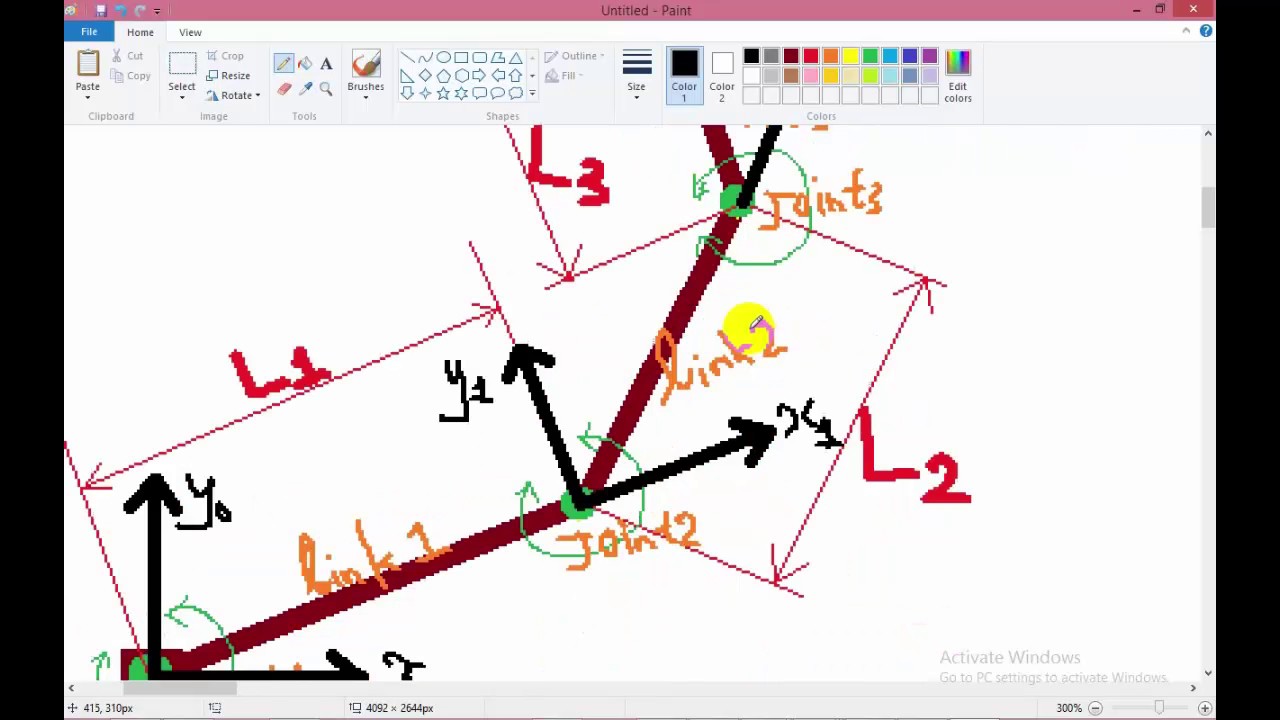









The degrees of freedom (DOF) of a robot is the minimum number of real numbers needed to represent its configuration space; a rigid body in 3D space has 6 DOF (3 translational + 3 rotational), while in 2D it has 3 DOF (2 translational + 1 rotational). Different joints contribute different DOF: revolute and prismatic joints provide 1 DOF, universal joints provide 2 DOF, spherical joints provide 3 DOF, cylindrical joints provide 2 DOF, and helical joints provide 1 DOF. Grübler's formula calculates DOF for any mechanism as DOF = m×n - ∑(joint DOF) - 1, where m is DOF per body (6 for spatial, 3 for planar), n is number of bodies (including ground), and the sum represents total joint DOF. This formula applies to various robots: a 3R planar robot has 3 DOF, a four-bar linkage has 1 DOF, a Stewart platform has 6 DOF at the top platform, and a Delta robot has 3 DOF at the end effector. Constraints reduce DOF—for example, a 7-DOF robot arm carrying a tray must constrain rotation around x and y axes to prevent spilling, reducing effective DOF from 7 to 5.
Degrees of Freedom of Robots Explained | Fundamentals of Robotics
Added:hi everyone and welcome to the third lesson of fundamentals of robotics today's lesson is about the degrees of freedom of the robot we will become familiarized with the degrees of freedom of the robot and we will find the general formula that we can find the degrees of freedom of any mechanism and not just the robotic [Music] arms i'm dr madison babariaso and i have a phd in mechanical engineering i worked mostly on robotics and mechatronics projects during my master's and phd work okay without further ado let's get started degrees of freedom of a robot is the dimension of the c space of the robot which in turn is the minimum number of the real numbers that are needed to represent the seed space of the robot beside the previous video that the configuration of the robot is the answer to the question where is the robot and we saw different ways to represent the c space of the robot so the degrees of freedom of the robot is the minimum number a minimum number a real number that is needed to represent the configuration of the robot or the c space or the configuration space of the robot a rigid body in 3d space has six degrees of freedom so suppose that this is x coordinate y coordinate and z coordinate so the rigid body has six degrees of freedom the motion along the x-axis the motion along the y-axis and the motion along the z-axis these are three of degrees of freedom it also has three rotational degrees of freedom rotation around the x rotation around the y and rotation around the z axis so overall it has six degrees of freedom three for orientation and three four positions so imagine this by taking three points on the rigid body for the first point there are three freedoms x y and z and there is no constraints for the second point we know that the distance between two points and the rigid body should be constant so b can only be on the surface of a sphere with center at a and this gives us two rotational degrees of freedom in other words three coordinates for b minus one independent constraint is two real freedoms for the third point the distance of this point to a and b should be constant so c can only be on the circle of the intersection of two spheres and this gives us one rotational degrees of freedom in other words with three coordinates for c and two independent constraints we have only one degrees of freedom for point d and so on the position of the point is fully determined and this there is no more freedoms in choosing the place of those points with the same analogy we can say that rigid body and 2d plane have three degrees of freedom two linear degrees of freedom and one rotational degrees of freedom suppose we have this rigid body on plane this toy car and the plane with x-axis and y-axis x-axis y-axis and z-axis as we saw a rigid body in 3d space has 6 degrees of freedom so if you confine a rigid body to the plane to this plane we will impose three constraints on it it cannot move in z direction because it's confined on the plane and it cannot rotate around the x or y axis and this means that there will be no roll and pitch angles so we will have three degrees of freedom you can also took three points on the rigid body so the degrees of freedom that we have for the first point is two okay x and y and there is no constraints the second point will be at the circle centered at the first point and the location of the third point will be fully determined so there so a rigid body in plane has three degrees of freedom now think about the rigid body in four dimensional space how many degrees of freedom does a rigid body in four dimensional space have how many degrees of freedom are rotational and how many are translational think about we have seen that a rigid body in 2d space has three degrees of freedom one rotational degrees of freedom and two translational degrees of freedom but why does this robot with two lengths and two joints it has two rigid bodies it has only two degrees of freedom but not three each link doesn't have 30 degrees of freedom the answer lies in the number of constraints that each of the joints put on the motion of the links so for instance in this two-dimensional planar robot each rotational joint puts two constraints on the motion of the link so the link cannot move in the x or y direction it only can rotate around the z axis so it only has one degrees of freedom so each joint provides one degree of freedom so the overall has two degrees of freedom so we should be careful when uh deciding about the number of degrees of freedom of a mechanism because the joints puts constraints on the motion of the legs or the rigid body if you imagine a robot in three dimension as the three r robot in this video that the three revolute joints these three revolute joints are apart from the end effector of the robot the revolute joint will put five constraints on the motion of one link with respect to the other leg so again it will provide only one degrees of freedom so this 3r robot will have 3 degrees of freedom other than its end effector because it has 3 rotational joints so up to this point we've learned that the constraints on the lengths come from the joints so now let's see how many different joints are used in different kinds of robots our blue joint as we saw in the industrial robot of the previous video is like a door hinge it provides one degrees of freedom of motion between two bodies that it connects the rotation is around the joint axis and the positive rotation can be determined using the right hand rule to the right hand rule if your thumb is in the direction of the rotation axis the positive rotation is the direction where your four fingers curl a linear sliding or prismatic joint provides the linear motion between two lengths it will again provide only one degrees of freedom between two lengths the robot in the picture has three prismatic joints so it has three linear degrees of freedom next is the universal joint which is two rotational joints that are orthogonal to each other so it can provide two rotational degrees of freedom these two rotational degrees of freedom are around the roll and pitch axis that are x and y axis the spherical or we call it shoulder joint or ball and socket joint is the same as this universal joint but it also has one another degrees of freedom the rotation around its axis so it has two degrees of freedom of the universal joint plus the rotation around the axis of the joint next is the cylindrical joint that can provide um independent translation and rotation around the single fixed joint axis so it can provide us with two degrees of freedom and the final joint that we want to talk about is the helical or screw joint that can provide a simultaneous translation and rotation around the screw axis so it has only one degrees of freedom the difference between this joint and the cylindrical joint that we just saw is that the cylindrical joint can provide independent rotation and translation around the joint axis but helical joint provides simultaneous rotation and translation around the joint axis so it only provides us with one degrees of freedom now let's talk about the grubler's formula grubler's formula is a general formula that we can find the degrees of freedom of any mechanism it's not just applicable to robots scrubler's formula states that the degrees of freedom of a mechanism is equal to the sum of the degrees of freedom of its bodies minus the total number of the independent constraints put on the motion of those body if you take n as the number of lengths note that traditionally we also take the ground as one of our lengths and if j is the number of the joints and if m is the number of degrees of freedom of a single body that is six for the spatial bodies and three for the planar bodies we can write the degrees of freedom equal to the freedom of the body minus the number of the constraints note that we deduct one from the end because we want to exclude the ground we have seen in the 2df planar robot example that the degree of freedom of the movement of one link with respect to the other can be found by deducting the number of constraints that the joint puts on the movement of that link from the degrees of freedom of a rigid body writing the grubler's formula in terms of the degrees of freedom of the lengths you can find variable and it can be it can be used to find the degrees of freedom of any mechanism remember that all constraints are independent now let's see some examples we saw before that our 2dof planar robot has two degrees of freedom now let's see if we can get the same answer with the grubler's formula so for the 2dof planar robot the m is equal to 3 because it's a planar rigid body so the rigid body in a plane has 3 degrees of freedom the robot has three links remember that um the ground is also a link we have two joints joint one and joint two and the sum of the degrees of freedom of the joints are two each joint provides us with one degrees of freedom so using the grubler's formula we can see that the 2d of planar robot has two degrees of freedom now let's step it up a notch and find the degrees of freedom of a four bar linkage m is equal to three because it's a planar robot we have four links because remember we take the ground as one of our lengths two we have four joints and the sum of the degrees of freedom of the joints is four because each rotational joint can provide us with one degrees of freedom using grubler's formula we can see that it has only one degrees of freedom we could also expect this result because suppose that the four bar linkage is a three r open chain robot that the two ends are pinned so the three 3r open chain robot as we saw before has 3 degrees of freedom so 3d uf of the serial chain minus two constraints uh gives us one degrees of freedom i reiterate that for the grubler's formula to work all the constraints must be independent now let's go ahead and see some spatial robots the first mechanism is a steward mechanism which is a parallel mechanism with six legs each leg has two spherical joints and one prismatic joint we can also replace the bottom spherical joints with universal joints with two degrees of freedom because it's a parallel robot each leg supports a fraction of the weight of the payload now let's find the degrees of freedom of the robot m is equal to 6 because it's a spatial robot and a spatial and a spatial uh rigid body has six degrees of freedom it has 14 links because um we have two platforms top platform and the bottom platform that provides two lengths and each leg has two lengths so six times two is the total number of the lengths of the legs so it has 14 links in total it has 18 joints because each um leg has three joints so 6 times 3 is equal to 18. and each leg has 7 degrees of freedom so overall it has 42 degrees of freedom for the joints so using rubler's formula the degrees of freedom of a steward platform is 12. of these 12 degrees of freedom only six degrees of freedom are shown in the top platform since the other six are torsional rotations about the leg axis so do you remember that the spherical joints have three degrees of freedom which one of them is rotation around the joint axis so there would be six degrees of freedom for the torsional rotations of the legs and they have no effect on the motion of the mobile platform because the top platform can move with full six degrees of freedom of a rigid body in its space the stewart platform is usually used to simulate airplanes this video shows the steward platform in action the top platform can move with six degrees of freedom of a rigid body now let's find the degrees of freedom of a delta robot delta robot is a parallel robot that can maintain the orientation of its end effector unlike the steward platform that can change the orientation of its end effector now let's calculate the degrees of freedom of the robot it has three legs and each leg has three revolute joints four spherical joints and five lengths thus uh we know that m is equal to three because um a rigid body in a space has fixed degrees of freedom uh it has 17 links uh because each of the legs has five lengths so three times five plus two platforms is 15 and 17.
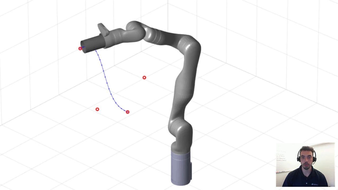
it has 21 joints because each leg has seven um joints the three times seven is equal to 21 and the sum of the degrees of freedom of the joints is 45 because each leg has 15 degrees of freedom so using grubler's formula we can find that the delta robot has 15 degrees of freedom but of these 15 degrees of freedom 12 are related to torsion of the 12 lengths because of being connected to the spherical joints these degrees of freedom are called internal degrees of freedom only three are visible at the end effector and the moving platform delta robot acts as an xyz cartesian positioning device this video also shows that only 3 out of 15 degrees of freedom are visible at the end effector and delta robot is like an xyz cartesian positioning device let's see another example consider a seven degrees of freedom robot arm that mimics the seven degrees of freedom of the human arm as you can see three rotational degrees of freedom for the shoulder joint one rotational degrees of freedom for the elbow and three rotational degrees of freedom for the wrist and assume that this robot should carry a tray with drinks on it the drinks shouldn't be spilled from the tray how many degrees of freedom does the robot arm have while satisfying this constraint here's a cool video of the semo robot serving food for the customers and carrying it frey you can see that he carries the food without spilling it satisfying all the constraints now let's solve a fun problem suppose that my r is a 7 degrees of freedom robot r 30 degrees of freedom for my shoulder joint it's a ball and socket joint right one degrees of freedom for my elbow joint it's a rotary joint right and three degrees of freedom for my wrist joint so overall the the the arm without if you uh don't take into consideration the fingers it has seven degrees of freedom so now let's suppose that i'm a robot okay so suppose that i should um the robot not me the robot should be specified a task that the robot should carry a tray with drinks on it the robot shouldn't spill the drinks so how many degrees of freedom the robot arm now have if um we put that constrained that the robot arm shouldn't spill the drinks so so the constraint that i put on my on the robot arm states that the drinks shouldn't be spilled so if the robot rotates it around the x-axis they would spill so no rotation around the roll if the robot tries to rotate around the y-axis or the roll or the sorry pitch at pitch axis the drinks for the spell again so we have two constraints the robot cannot rotate the drinks around the x-axis it also cannot rotate the drinks around the y-axis so we put two constraints it can move in this way in this way in the z-axis and it can rotate in the z-direction but it cannot rotate in the x-and-y direction so the robot arm with these two constraints would have five dofs well that's going to wrap up today's lesson thank you everyone for watching and i hope you enjoyed this video and i hope you also get a good understanding of the degrees of freedom of the robot and also the grubler's formula to find the degrees of freedom of the mechanisms and especially the robots i hope to see you in the next lesson bye bye
Up Next

Inverse Kinematics of 2 and 3 DOF Robots Explained
@eliasbrassitos1
2.4K views•2020-10-16

MathWorks Virtual RoboSub Simulation Environment | Webinar 2026
@RoboNationInc
209 views•2026-03-10

How to Build a Self-Balancing Robot: Arduino Nano & MPU6050
@easytechzones
16.8K views•2022-03-09

Micromouse: The Fastest Maze-Solving Robots on Earth
@veritasium
23.5M views•2023-05-24
Related Study Plans & Knowledge Roadmaps
Structured learning paths in Robotics