Micromouse: Hardware, PID Control & Flood-Fill
Learning Goal: Design, build, and program an autonomous Micromouse maze-solving robot using a Teensy microcontroller, implementing IR distance sensors for wall detection, DC gearmotors with encoders for precise PID movement, and the Flood-Fill pathfinding algorithm for optimal navigation.
- Prerequisites: Basic knowledge of C++ syntax (variables, loops, and functions), introductory high-school-level physics (voltage, current, and mechanics), and a computer capable of running the Arduino IDE and KiCad.
- Estimated Total Study Time: 35 Hours
Module 1: Electronics & Teensy Microcontroller Basics
This module establishes the foundational hardware and software framework for your Micromouse robot. To align with modern competitive standards, you will shift from breadboarding to custom PCB design. You will explore power distribution networks, set up the 32-bit Teensy development environment (Teensyduino), and learn to use KiCad to design a lightweight, robust custom PCB that serves as both the circuit board and the physical chassis.
Recommended Videos
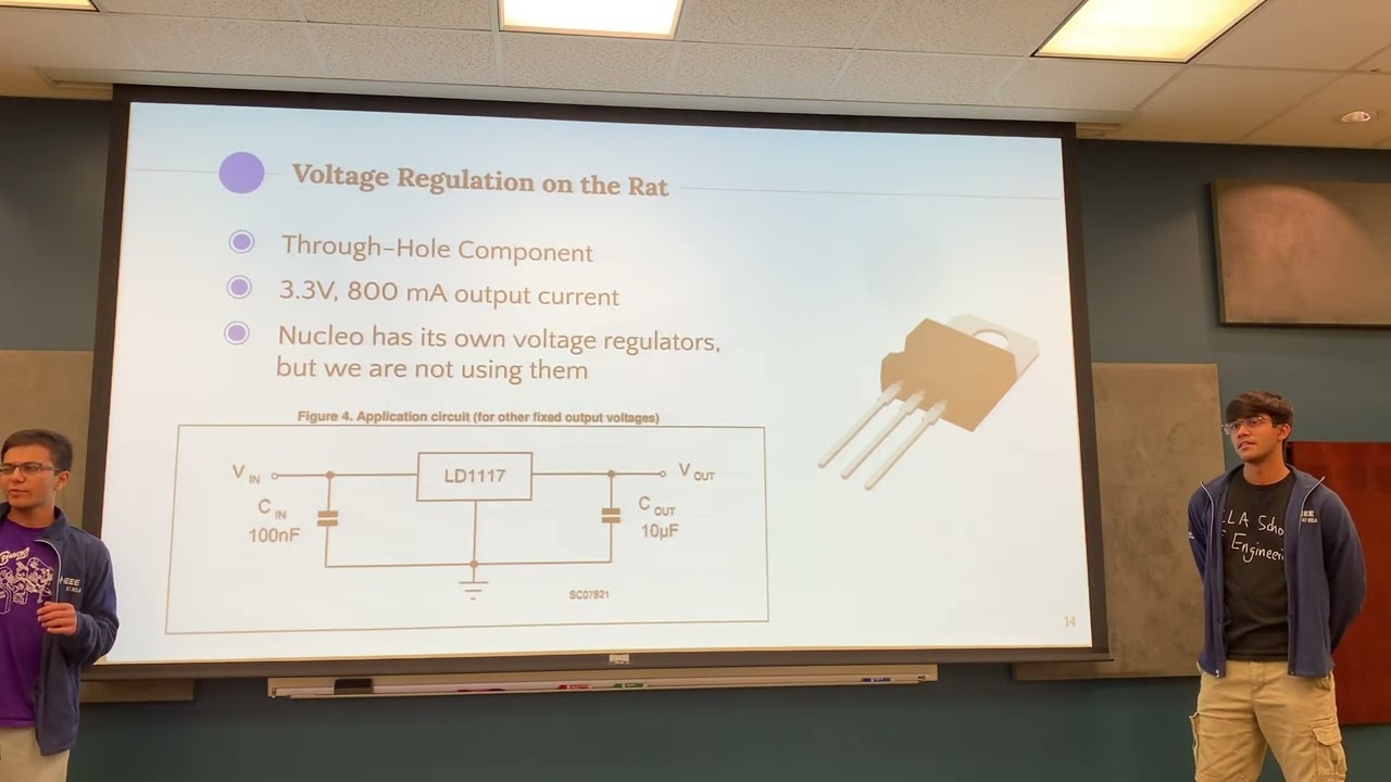
Why this video
This lecture provides a foundational introduction to the power requirements of a Micromouse. It explains why Lithium Polymer (LiPo) batteries are preferred for their superior power-to-weight ratio and details how to design proper voltage regulation systems to prevent noise from motors from disrupting your 32-bit microcontroller.

Why this video
This video explains the transition to the high-performance Teensy platform within the Arduino IDE. It covers installing the Teensyduino add-on and setting up digital input/output pins. Understanding this workflow is critical for utilizing the Teensy's 32-bit hardware capabilities.
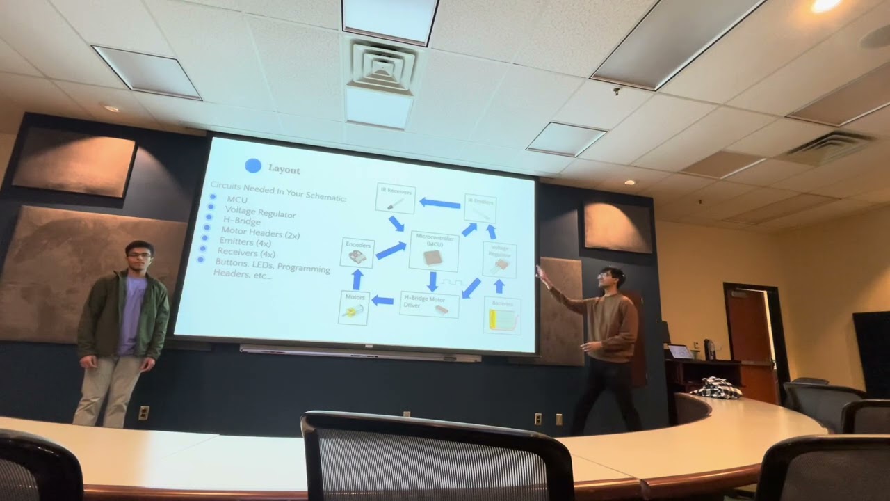
Why this video
Custom PCBs are essential in modern Micromouse design to meet strict weight and size constraints. This lecture guides you through sourcing electronic components via distributors like Digi-Key, reading datasheets, and mapping schematic symbols to physical footprints specifically for Micromouse components.

Why this video
This video provides a practical, comprehensive guide to KiCad, the industry-standard free PCB software. It walks through schematic capture, footprint association, manual routing, and generating Gerber fabrication files, taking you from initial concept to a manufacture-ready PCB design.
Knowledge Checkpoint
- Understand the power delivery requirements of a Micromouse, including why LiPo batteries are used and how buck/boost regulators stabilize voltage.
- Successfully install the Teensyduino framework and upload a basic sketch to a Teensy microcontroller.
- Read component datasheets to determine pin configurations and voltage ratings.
- Draw a custom electrical schematic in KiCad, map symbols to physical footprints, and route trace connections on a two-layer PCB design.
Module 2: Sensors and Actuators: Motors, Encoders & IR
To navigate a maze, a Micromouse needs high-speed actuation and reliable sensory feedback. This module covers driving DC gearmotors using dual H-bridge motor drivers, using hardware-based rotary encoders to track distance, and setting up analog infrared (IR) emitters and phototransistors to detect walls.
Recommended Videos

Why this video
This lecture explains the electromechanical actuators used in Micromouse robots. It focuses on brushed DC motors, dual H-bridge drivers for bidirectional movement, and how quadrature encoders measure wheel rotation to provide feedback to the microcontroller.

Why this video
This video details how to design and position infrared emitter-receiver pairs for wall detection. It covers the electronic principles of reading raw analog voltage values from phototransistors and explains how distance relates to light intensity.

Why this video
High-speed robots cannot rely on polling to read encoders. This tutorial demonstrates how to configure hardware interrupt service routines (ISRs) on microcontroller pins to track quadrature encoder signals in real-time without blocking execution.

Why this video
This video walks through the physical calibration process for infrared sensors. It demonstrates how to place the robot in a standardized maze corridor, record analog sensor values at incremental distances, and adjust sensor alignment to ensure consistent readings.

Why this video
Analog IR sensors output non-linear voltages relative to distance (). This lecture explains how to convert these raw ADC values into physical measurements using a lookup table, a highly efficient calibration method for resource-constrained microcontrollers.
Gap Coverage & Technical Integration: Calibration Milestone
Before moving to closed-loop control, you must calibrate your sensors and test your motor drivers. Follow these steps to map your IR distance sensors and step-test your encoders:
- Physical IR Calibration: Place your constructed robot in a test environment with official white walls. Place the robot at measured distances from a wall (from 20 mm to 150 mm, in 10 mm increments).
- Lookup Table (LUT) Generation: Record the 10-bit or 12-bit Analog-to-Digital Converter (ADC) values for each distance. Write a simple Python script or Excel sheet to generate a C++ lookup table matching ADC thresholds directly to physical distances in millimeters.
- Encoder Pulse Verification: Manually push your robot forward exactly 180 mm (the length of one standard maze cell). Count the rising and falling edges registered by the Teensy’s hardware interrupts on Phase A and Phase B. Compute your encoder counts per millimeter (CPMM):
Knowledge Checkpoint
- Explain how an H-bridge driver controls the speed and direction of a brushed DC motor using PWM signals.
- Read quadrature encoder signals using hardware interrupts and calculate the exact direction of rotation.
- Build a calibration lookup table (LUT) in C++ to translate non-linear IR phototransistor voltages into physical distances (in millimeters).
- Complete encoder step-testing and calculate your robot’s precise counts-per-millimeter (CPMM) constant.
Module 3: Precision Movement: Implementing PID Control
A Micromouse must travel fast without colliding with walls. This module covers feedback control theory, focusing on implementing a Proportional-Integral-Derivative (PID) controller. You will learn to use your calibrated IR sensors and encoder readings to keep your robot centered in a corridor, perform precise 90-degree pivot turns, and manage acceleration using basic velocity profiling.
Recommended Videos
Why this video
This lecture introduces closed-loop control for Micromouse navigation. It details how to calculate tracking errors from left/right IR sensors, write code for Proportional (P), Integral (I), and Derivative (D) error corrections, and tune gain constants (, , ) to keep the robot centered.
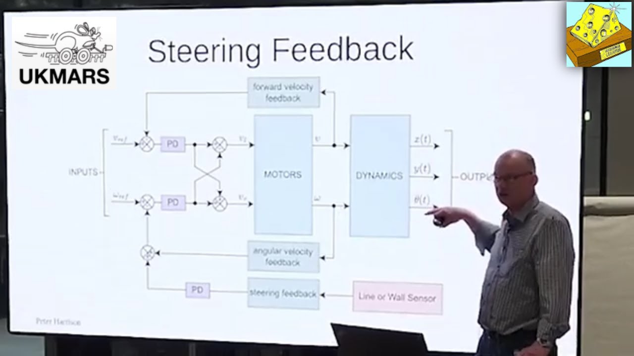
Why this video
Presented by world-renowned builder Peter Harrison, this video covers the dynamics of wall tracking. It explains how to handle two distinct tracking challenges: angular error (the robot's heading relative to the walls) and lateral offset error (the robot's position relative to the center of the corridor).
Why this video
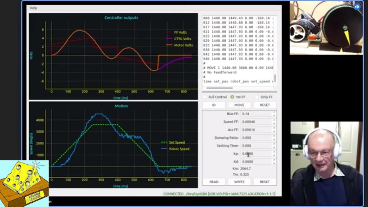
Tuning PID loops through trial and error can be slow and risky. This in-depth video models the electromechanical properties of a Micromouse DC motor as a first-order dynamic system, showing how to derive stable PD controller gains analytically.
Knowledge Checkpoint
- Understand the individual roles of the , , and terms in a closed-loop controller.
- Write a C++ feedback loop that runs on a timer interrupt at a fixed frequency (such as 1 kHz) to compute the correction value:
- Differentiate between angular heading errors and lateral offset errors when tracking walls.
- Implement a basic trapezoidal velocity profile (acceleration, constant speed, and deceleration) to prevent wheel slippage during sudden starts and stops.
Module 4: Pathfinding: The Flood-Fill Algorithm
Once your robot can move reliably, it needs an algorithm to find the shortest path through the maze. This module covers the mathematics, spatial representation, and C++ implementation of the Flood-Fill pathfinding algorithm. You will learn to model the maze as a virtual grid, maintain an internal wall map, and update cell values dynamically during exploration.
Recommended Videos

Why this video
This lecture provides an excellent introduction to the Flood-Fill algorithm. It demonstrates Manhattan distance calculations, visualizes cell valuation updates using step-by-step animations, and explains how to represent walls and open passages in memory using C++ bitwise operations.

Why this video
This walkthrough of the open-source Maze Runner Core framework explains how to organize your code cleanly. It details the separation between low-level hardware abstraction layers (HAL) and high-level decision-making logic (pathfinding state machines).

Why this video
This video explains how to manage dual maze representations (known vs. unknown/unexplored walls) to distinguish between exploration and fast runs. It details how to optimize search routines to map the maze safely and calculate efficient speed runs.
Knowledge Checkpoint
- Explain how Manhattan distance works and initialize an empty grid where the center destination cells are set to .
- Represent wall configurations using bitmasks (such as North =
0x01, East =0x02, South =0x04, West =0x08) inside a single byte per cell. - Write a dynamic queue-based Flood-Fill algorithm in C++ that recalculates cell distances whenever the robot detects a new wall.
- Define the differences between "exploration mode" (mapping the maze safely) and "speed run mode" (executing the optimal path).
Module 5: System Integration & Maze Testing
In this final module, you will integrate your physical hardware, control software, and pathfinding code into a completed robot. You will review mechanical assembly techniques, organize your software structure using a central state machine, calibrate your robot for full-speed runs, and explore the history and competitive boundaries of the world's oldest robotics competition.
Recommended Videos

Why this video
This video shows the practical physical construction of a Micromouse. It highlights surface-mount device (SMD) and through-hole soldering, motor mount installation, and the mounting of passive components, providing a helpful reference for final assembly.
Why this video
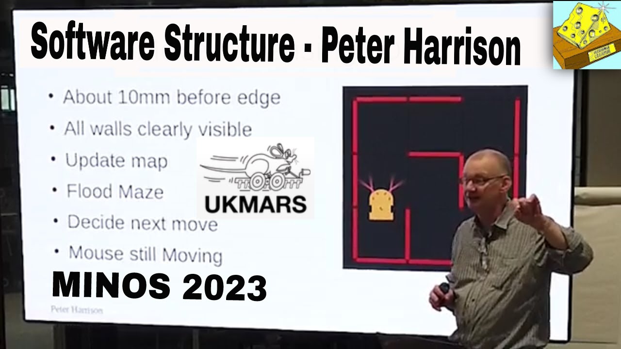
This presentation details how to structure a Micromouse program. It covers implementing a high-level state machine to coordinate different phases of a run (power-up, user selection, exploration, path planning, speed run, and return-to-start) and manages high-priority interrupt tasks.

Why this video
This highly viewed Veritasium documentary offers excellent context for your work. It traces the history of the Micromouse competition since 1977, details advanced engineering designs (such as six-wheel custom fan suction setups), and explores the optimization strategies used by top competitors.
Knowledge Checkpoint
- Assemble your custom PCB and verify that all solder joints, power planes, and components are installed correctly.
- Write a master state machine in C++ that manages transitions between states like
IDLE,EXPLORING,CALCULATING_FASTEST_PATH, andSPEED_RUN. - Handle task priorities by separating background calculations (like Flood-Fill updates) from high-priority interrupts (like PID motor loops).
- Conduct iterative test runs in a real or simulated maze, adjusting wall-tracking parameters and turn speeds to reduce physical error drift.
Course Map
Key People Index
- Peter Harrison: A leading figure in the international Micromouse community, known for his work on the UKMARSBOT platform and detailed tutorials on wall-tracking dynamics, PID modeling, and clean software structures.
- Claude Shannon: The legendary "father of information theory" who designed and built "Theseus" in 1950—a copper-contact electromechanical mouse that used telephone relays to solve a maze, laying the groundwork for modern micromouse robotics.
- David Otten: A prominent MIT researcher and legendary Micromouse competitor who developed foundational techniques for mechanical mass distribution, including centering the robot's weight over its wheels to reduce slippage during high-speed pivot turns.
Final Self-Assessment
To verify your work, ensure you can check off each of the following system requirements:
- Custom Schematic & Layout: Your KiCad schematic features a dedicated power stage (e.g., a linear or switching regulator stabilizing 3.3V/5V rails from a 2S LiPo battery), and the routed PCB functions as both your electrical board and your mechanical chassis.
- Teensyduino Integration: The Teensy microcontroller runs a C++ program and uses hardware timer interrupts to execute motor-control loops at a fixed interval (e.g., 1,000 Hz).
- Bi-directional Drive Verification: The dual H-bridge driver handles high-frequency PWM signals, allowing both DC motors to spin in both directions without electrical noise resetting the microcontroller.
- Quad Encoder ISRs: The encoder interface uses high-priority hardware interrupts on change (rising and falling edges of both Phase A and Phase B) to track position without losing steps during sudden movements.
- Sensor Calibration Map: The analog IR emitter-phototransistor pairs are mapped using a C++ lookup table (LUT), outputting distances in millimeters with a standard error of less than 5 mm.
- Corridor Centering Control: The PD/PID controller computes a tracking error from your left and right IR sensors, modifying individual motor speeds to keep the robot centered in a corridor.
- Turn Execution: The robot executes precise 90-degree pivot turns and 180-degree U-turns by running closed-loop encoder feedback control on both wheels.
- Flood-Fill Pathfinding: The robot maintains a virtual grid map in memory and successfully updates cell distance values using a queue-based Flood-Fill routine when a new wall is detected.
- Dynamic State Machine: The software architecture is organized around a clear state machine, coordinating navigation phases from initial exploration to executing a high-speed run.