














IR sensors in micromouse robots use infrared LED emitters and photo transistor receivers to detect maze walls by measuring reflected light intensity; the system requires careful circuit design with transistors and resistors to control current, and software implementation that averages multiple readings and sets thresholds to distinguish walls from open spaces, while accounting for ambient light interference and sensor calibration needs.
Micromouse IR Sensor Circuits: Emitter, Receiver, and ADC
Added:Fundamental circuit theory, including Ohm's Law, voltage dividers, and the basic operation of diodes and phototransistors.
The conceptual difference between analog and digital signals and the purpose of Analog-to-Digital Converters (ADCs).
The physical properties of Infrared (IR) light, specifically how it reflects off different surface colors, textures, and angles.
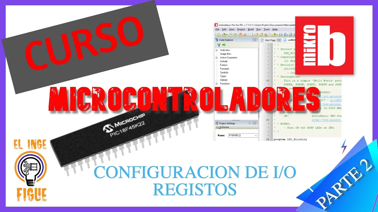
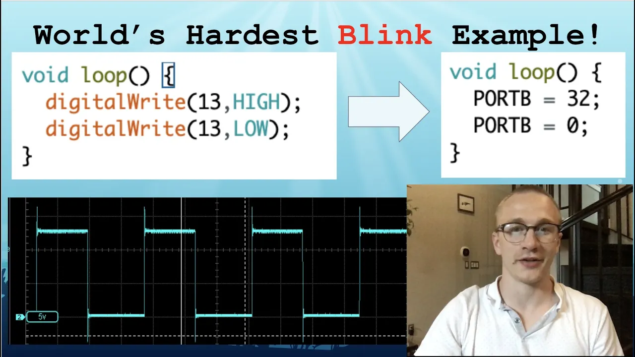
Basic microcontroller architecture and programming, particularly reading registers and configuring input/output pins.
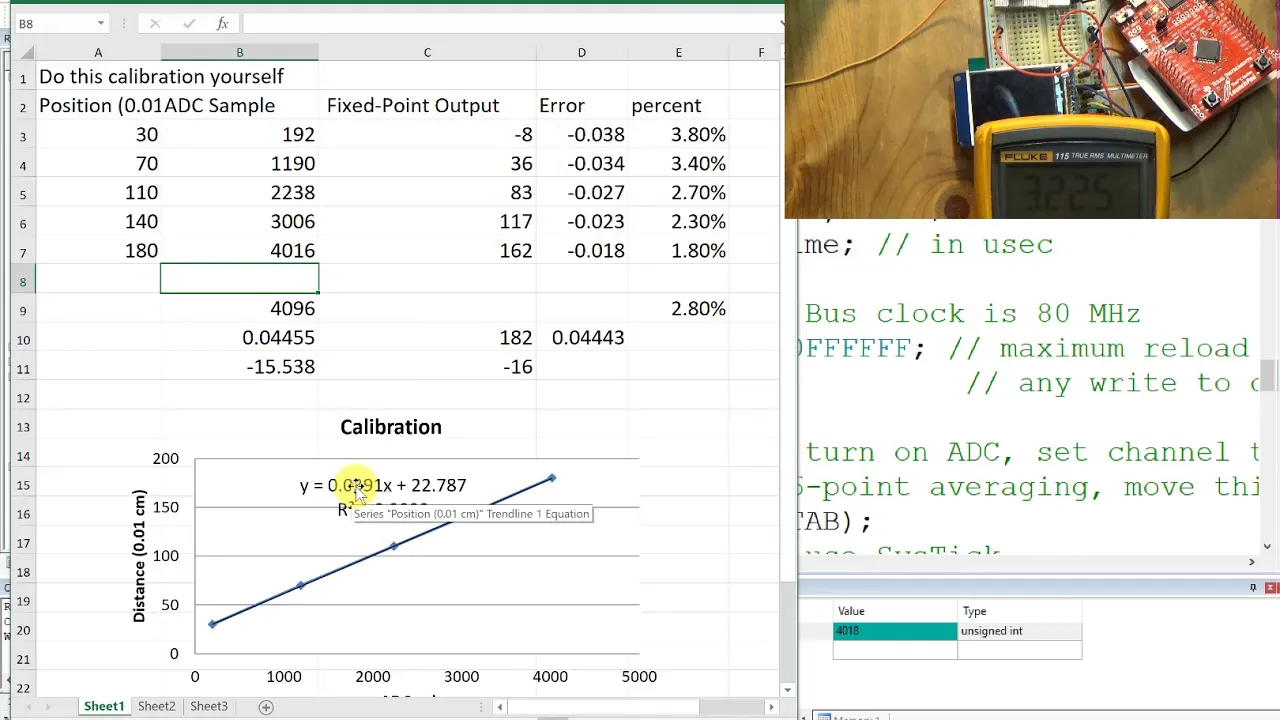
Sensor calibration and linearization techniques to convert raw ADC voltage readings into precise distance measurements.
Dynamic ambient light compensation algorithms, such as pulsing the IR emitter and subtracting background noise.
Implementing Proportional-Integral-Derivative (PID) feedback control loops for wall-following and center-alignment navigation.
Integrating sensor-derived wall-detection data with maze-solving algorithms like Flood-fill to dynamically map paths.
737 views5likes54:45Original Release: 2025-01-15
all right are we good yeah okay everybody Welcome to our fourth and final micromouse lecture of this quarter yay today's lecture it's going to be on IR sensors please scan the QR code if you haven't already so here's a quick overview of what we're going to be going over today so of course we're going to be talking about IR sensors and we're going to be discussing what they are and why exactly we use them so there are actually two parts to our IR sensor system and that's our IR emitter circuit and that's our IR receiver circuit so the IR emitter circuit that's going to be responsible of basically um emitting um pulses of infrared light and then in our case it's going to be bouncing off these walls and then when you get these pulses back they're going to be measured by our IR receiver circuit and basically tells us um it allows us to see the walls of the maze to detect if we get them and then we're also going to be um discussing the software and how exactly um we use the value we get from our IR system all right investigate okay so we're going to go over how our IR sensors actually work some you guys might already know this basically an infrar LED so the objects nearby are going to reflect this light back to us and closer objects will reflect more and farther objects will reflect less that's like you could imagine that because like I don't know density of less of ites things that are far away or something like that and then our photo transistor which is our IR receiver or our IR sensor same are going to detect that reflected light and this is going to change the volage which is read by our our MCU and that's how we're going be able to measure like how far things are so uh the infrared LED that we use it's it's like it's like the same as on an LED except this time it's infrared light you're display that and then the photo transistor is what we use to basically detect everything and then if you look at that bottom diagram basically shows like the intensity that we read um coming off like these pulses of infrared light like bouncing off the walls in our case it's not linear and it's like 1 over D2 yeah we'll discuss more about how they work but that's a general like so get all this okay so why IR sensors have you guys ever worked with like ultrasonic sensors yet yeah okay you'll probably be working with ultrasonic sensors a lot in like in your physics like lab classes but you might be wondering why don't we use that instead of ir sensors well ultrasonic sensors they're very bulky so imagine having like four of those on your little r and that would be like insane that would be like insane so that's like a large reason of why we use IR sensors more it's because they're like could fit a lot more in our casee um we have groupings of to for our IR sensors so that's going to be an IR receiver and IR emitter so we have one on the left side to detect left walls uh one on the right side to detect the right walls and then two of these pairs to detect the front walls basically and then not only that um they're contactless so um you're able to detect the walls from far away which is exactly what we want whereas um if you did use like um I think touch sensors or like um I think switch sensors I'm not sure but like yeah yeah but like you have to make contact with the wall so that's bad which is also why we use IR sensors and another Pro is that when you use IR sensors they're giving you analog values and this means that you're getting like a wide variety of values that you can then like um set a threshold for detecting a wall like say you're getting a value of like 750 then you're like hey I detect a LW 750 and this allows you to basically just me the distance you guys have any questions you guys know it only be Z does it like a straight line yeah we'll uh we'll go over that how not get yeah so okay we'll discuss that more but essentially like it doesn't um like you like for all these pairings um like you want to turn like one of the IR emitters on and then like have basically one pair working at a time or else if you're emitting light like right here and you're proceeding light from here um this light might like interfere with this one so that's not good so we turn on one pair at a time but for the pairs I'm pretty sure the IR emitter like emits it so that like or might be at like a time interval so it doesn't interfere with like the light you're getting I think are you asking like why the one doesn't right next to it doesn't interfere with the right next to it right next to it basic it's just because it's not like a light goes cone in Fr I mean so like this is our this is ourter this was already be gone over but it doesn't matter I don't know how you spell actually so I'm stop uh it shoots out like this so it's not like I actually don't know what the receiver is but like like it just receives it that's all yeah rece I it might be from every dire I'm sure you can Google and say also wait is there slight delay that's also it doesn't yeah yeah that's also like I don't know if we go over that in this but basically like it shouldn't be too big of an issue but like because we have like we could have multiple these running at once we don't want like this is another emter we want this thing this receiver to only like pick up what is like being illuminated by this light so we keep the other ones we keep this other emitter off while this one is emitting so that uh this doesn't pick up anything from this or like that so once this is done like this has read a nice value then we'll turn it off and then we'll emit from right here and then read right here around it if you look at the IR transmitter receiver pair one of them is blackened right so that blackened uh portion prevents the other receiver from like that's it's not that's not a rule like uh there's actually they can actually like come in like anything yeah they can come in anything so like I actually don't remember which one is in thise like let's say the emitter is black and the receiver is white oh or clear I've seen the opposite yeah yeah like like this one is just to different shap that's why we have these colors but they could like both of them could be white both of them could be black oh both of them could yeah I I'm sure there's a reason they're different in like was that one of the sensors blackened out except for the very so that in a nose cone type of fashion and then the other like the receiver receives it from all sides like if the receiver is black then the sensor can emit everywhere and the receiver just are you saying you know that's true or is that's no I'm just cuz I don't know if that's true because like I've said I've seen I've seen aits which are yeah we see like white and black like white and so I've seen I've seen now okay so like some bad things about IR sensors probably the biggest bad thing is like ambient light can cly affect it and like the worst C the sun because the sun emits ton of infrared light and so basically our micro is not going to work very well outside or like places where there's a lot of like Windows like that um if any of you like saw me at some and there was yeah there mic demo and I was trying to cover it and stuff like that it's I was trying to make it work outside but it wouldn't I guess it's like a case for Ultrasonic sensors or something like that but the upside also like always comptition it requires calibration to measure actual distances so like it kind of goes with this thing there's one it kind of goes with these two on the bottom which is like that there are variations between identical sensors and different materials like wall materials will give different readings basically like a value of like 2,000 that we read like an analog s of 2000 doesn't mean anything except for what we interpret to me that Mak sense so like if we put our Mouse one inch from the wall and we get a value of 2,000 we're going to like then program our Mouse and say like okay you going Val 2,000 that that means you're one in from the wall doesn't because you could another sensor on your same Mouse could be like 700 when you're in that so they're not precise measurements it's just like you're have to and then the same thing earlier about scaling distances how Works basically these reads that you're getting from your IR receivers they're going to vary so like depending on like what room you're in you might have C that's like the main part oh yeah that's an important thing also different rooms like especially because some might have more ambient light from the sun or something like that or you going have to recalibrate yeah so during competition you could have okay but like during competition since like if you're working the lab 247 you're like making sure it works in the Maze like during in the it lab when you go to the competition which is just like like engineering like probably six like um like light might be different so you just have to recalibrated bit okay now we're going to be discussing the analog IR emitter circuit so what is this big circuit well that's our irit circuit so this is actually what you're going to be designing and I think assignment for me um don't worry if it looks very like big and complicated we'll go over everything okay so here's a brief summary of like how it works we'll talk about it a lot more but um if it kind of looks familiar you're right it kind of looks like motor one right like how we power on our Motors um in this case we're using an IR led to emit IR light right like usually you want an LED to light light up like green blue blah blah blah but you want this this led to do infrared light so this is going to be our infrared light and it's going to be in a form of a diode um in this case to basically power on our IR IR emitter um we use a transistor to turn it on or off and this is because the MCU doesn't supply enough current by itself so we have to directly hook it up to a battery which is kind of like the same visiting we had with our Motors so depending on whether the MCU pin is high which means that it's on it's going to basically turn on or off our transistor and our transistor basically acts like a switch so if the switch is on it's connecting the circuit allowing current to flow and if it's off it's not allowing to current to flow um so let's give example here so our MCU pin is high that means that it's on so it's going to connect our IR emitter's current from here to ground and this basically allows current to flow from our battery to that resistor to our IR emitter and then to ground and this essentially allows our led to be high which means that it's and otherwise um say our MCU pin was low um It wouldn't connect I mean the transistor would would be off and there would no there would be for current to travel from the IR to ground and that way the IR would be off you guys have any any questions about what I just yeah well what what's the purpose of the capacitor and okay okay I perfect yeah we'll go into that in like like basically just that SL we'll go over it one okay so yeah I don't know how useful all this information is but that's the mod our IR emitter uh the voltage forward basically because our emitter is a diode like you ever use LED you know it's a diode the voltage or current can only flow one way through it uh uh is 1.3 volts our maximum current is 100 milliamp for the specific and then the wavelength which it emits is 880 n which is like I don't know it's also uh then like what I was saying about this earlier a 15 Vie angle so one important thing to note is that the wavelength is 880 Nan did not say that no no I okay okay yeah but it's it's that so one thing is um when you actually do make your micro Mouse right um we give you suggested parts that you guys to choose from um but if you do choose to like pick your own IR emitters and receivers make sure that they're they're compatible in terms of wavelength because like if your IR emitters like sending out 880 nanometers and your receivers like like take something else like that's way off it's going to be bad so just make sure that's consistent uh but otherwise B like specific I thought em and receiver ciruits come in here so already uh I mean what do you mean they could come in air you could make circuit which is like I'm sure like I think they maybe the ones I've worked with they were hooked like a small breakout PCB board that has it on it same time right yeah we ours aren like that like we literally like your part is going to look like this like two likeit you guys solder on the the IR that's this is like literally what your things are look like look like you ever use like oh you ever use LED in a r board or something like that and they look like this that's all you're going to get then uh your uh but on your own Mouse you'll have to make a circuit ass so this is all you have there's no like board with the two things on it already that has like a bunch of stuff happening inside of it so yeah but you basically just purchased these parts so they're separate so you might have to but if they do come in pairs yeah you're pretty stuff um this is now we're going to be talking about moset and in our case uh we use the n n moset um it's basically a type of transistor you'll learn about this in your upper division E classes low key learning this right now um but essentially like I mentioned it basically just controls current flow from the IR M to ground to allow current to flow through and it's basically necessary to turn um emitters on or off because you don't want it you don't want your emitters running like all the time because of power and stuff um also it turns um turns on emitter when MCU pin is high like I mention so what you mentioned these capacitors and basically they're they're there to stabilize Supply voltage for uh like from constantly turning on and off the transistor like if you what other thing we have it was like our motor driver or something we uhac as well stabilize our voltage and that's basically what they're there for they also reduce the turn on time so like the our our IR emitters will turn on faster because the capacities um and that's good because we want turn fast off because of like what we talk about turn on read it and then turn it off the faster we can do that the more like real time uh yeah more real how do that's a great question um a lot of like circuits like we've talked about they always have capacitors and that's usually just to smooth out like volage spikes and stuff um in this case why it's bypass um not too sure but um it does I think I think the difference between like the difference between bypass Capac that's my yeah because like like our reasoning why it kind of like reduces the time to turn on for IRS is because when this is when your MCU pin is low um this transistor which acts like a switch right it's going to be off or um which means that there's no current flow in this Branch right but that means that there's still current flow inside the the other branches right so like it won't go through R4 that resistor but it'll take the other current path and that means that when you do turn it on it doesn't have to go from the battery all the way to this transistor and down there's already like current flow going on like right above that node so I think that's why like it's it it reduces time I don't know how you decide like we didn't make the schematic was like a long time ago but I'm guessing just good practice for I think this would probably work without those but it would probably be less like to add on to that how do you choose your capacit because you guys have chosen like 4.8 micr don't know we that I mean because this this again the circuit we didn't make make a long time ago uh either CU like a lot of the time like these values don't necessarily are like perfect values like if you 4.8 uh that micro micro thought like this wouldn't work at all like could proba work the same basically um so either of the people that made it uh did some calculations or like these are the closest things or like they just guess or something or like experiment I'm guessing they did some rations also two capacitors would actually no different Capac values might have like maybe like robust effect or something like yeah I'm not too sure but I think like mosto Capac AR always yeah I'm not not too sure all right wait so okay so in short PNP npn and mosfets they're all types of transistors right so they all basically just like connect it or don't connect it um the difference between PNP and npn is the type of material that's used so um you'll learn about this like d you're probably going to learn about uh like they here like I am right now but um there like different types of semiconductor types so like npn it's going to be like n doped and then p in the middle which is positively doped and negatively doped again sorry it sounds confusing but basically they're different materials for MP and PNP that's like the that's like the main difference and then for mosfets the difference between that is like let me see uh if you want after after after this I can show you exactly like a l diagram and explain it but yeah I don't exactly know how like they function differently but they they do act like a basically trans like a okay now we're going to be talking about the MCU pin current limitter um so that's basically just this one resistor right after the MCU and what it does is basically it limits current flow from the MCU to the MOs gate um and basically without this resistor um there would be too much like current that might potentially damage the MOs so that's why we have aist to basically that all right and then here's another resistor um so here's our another resistor called our full down resistor so basically uh this is going to anyways uh well one thing it does is basically um when our or my MCU pin is not applying like voltage anymore so there's no uh more reason for current flow the current can't flow back to the MCU pin and so it needs to flow somewhere and so rather than like oh wait that's what so rather than it like applying voltage to the base of the transistor again we want it to instead flow down to ground and do that through this resistor um and the reason for the extremely high value here like if you notice like this is which is a lot greater than 100 OHS 51 ohing for the other circuit is because we want to keep the current draw low when the MCU pin is actually applying so like if you notice I mean I'm just here so basically when the uh pin is applying or okay when there's current flowing through here to to try to get through the to the pin it also wants to flow through here but because of the extremely high resistance a lot less of the current is going flow down through here then it's going to go through here like if this was a lot lower the value the current would have a lot easier time flowing down through here um and we don't want that we want most of the current to go through here that makes sense like I mean if you guys know like uh Bal I you know why that makes sense um and also the reason we have this as opposed to it kind of goes into the explanation I just saying the reason we have this is supposed to not having this because IM there's no resist here and just a wire is because then if we applied our our voltage and there was current flowing through here would just flow through here the ground instead of going the Bas but basically just to restate what Michael said it's basically we're explaining like why we need this path at all like would it still function even if we didn't have this path to this path and that's because um right when you turn off say the MCU is on right right when you turn off the MCU current's still going to be going here and then the voltage here there's like current that's here has a path towards ground but then U what about like excess voltage here where's it going to go right you don't want to accidentally like turn on your LED so um for a way to basically like dispose of the charge here you have to make a connection to ground which is exactly why we have a connection from here to here and but then this leaves it because there's like a short and you don't want a short because then it will never take this path at all which is why we need a resistor and then um with this resistor then charge can go from here to here when the MCU is off and the reason for why it's high is because like we don't want when it is on we don't want any Curren going through here you want like most of the current to be turning on this transistor does that make sense okay so now we're going to be talking about the LED current Li and what is that well that is just our little resistor at the top so basically what it does is it limits the current through the LED since um the battery's current is like it could be potentially like very high and dangerous so we want to limit that with our resistor and how do we exactly calculate for this resistor value I know we weren't able to calculate for our capacitor values but we are able to calculate for this resistor value and um the voltage that Supply also represented by BCC is 3.3 Vols right um and our ideal IR emitter forward voltage um it's called forward voltage because um LED it's a light emitting diode and diodes only like they only want current to flow in One path so that's why we just call it Forward um but our ideally we want this voltage drop to be 1.3 volts right so if the if the voltage drop across this IR emitter is 1.3 volts where does the extra two volts come from right so we have to make sure that it drops an additional 2 volts um for a resistor and basically what this is saying is 3.3 minus 1.3 volts is 2 volts so besides this IR emitter U voltage drop we have to somehow like drop this voltage again and that's where we have in a resistor and our desired current through our um through the what's it called LED is 40 milliamps so if you do V equals IR you're able to calculate for the resistance we need so that it'll reach like the optimal voltage drop does that make sense okay basically like if you well a lot of times in these circuits like just like filling it up with resistors to make sure that it's like safe um but this is like the last slide for our IR emitter do you guys have any questions or you guys want like again yeah what's the general current flow does it start from the 3 and then remember always remember that current is going toow from our high voltage to low voltage so round by the way is like low volage usually considered zero volts so 33 Vols is 33 Vols so it's going to flow 3.3 Vols all the way down to ground and then I guess also there's the volage MCU as but this is okay this is General path so say like a lot of what you just like said like oh like which path is current taking stuff it's dependent on this MCU pin if it's on or off right let's say it's off there's going to be no current like here it's all going to be on the right side so it's just going to go through the two capacitors and then to ground right but as soon as we turn on this MCU it's going to allow current to flow um in this branch in which case it will turn on the IR emitter flow down to the transistor and then back to ground and then right when you turn it off this path is going to be closed again and then um left over charge is going to go from this ground through that resistor all right let's the circuit okay so our photo transistor which is what you see which is that q1 thing if you I mean actually I'll say you look at it closely it's also a transistor uh that's going to act like a switch but instead of like applying a a voltage to the base the amount of reflect like the amount of IR light that it receives or that's reflected off of an object is going to control can flow through uh like well through the transistor and then also through the resistor and so depending on uh that current that that the transistor allows to flow there's going to be a different voltage drop across the resistor and then this the reason that voltage drop matters is because that voltage drop we can measure with our mcu's ADC uh functionality which is analog to digital converter so so basically oh yeah see uh basically the more reflected light that that uh that the transistor receives the more current which is allowed to flow through here and the more current that's allowed to flow through here the greater the voltage drop across this resistor is going to be so actually you can imagine it more like the greater the voltage is going to be right here if that makes sense because of V ir and so like you know so in case you don't know I guess saying it like vs vol I equal current and R is the resistance but uh basically if we increase I in that I the voltage here is going to be greater or the voltage drop across this this is ground which is zero um is going to be greater and then we can measure that which out by the way going to our MCC digal con and that's how we're going to read thec work so ADC analog to digital conver we the MCU actually handles all of the conversions but ENT essentially like what you're getting in this output it's going to be a range of values in terms of voltages right but we want like defined values so like digital values like like 700 blah blah blah so it's going to convert like a range of voltage values into um just like digital values that you can like read like oh 500 800 yeah I'm not exactly sure how exact converts it but well let's imagine so like ition digital uh signals earlier if we didn't if we only connected this to like a um what's it called a digital like I don't know receiver pin or something like that it's basically just going to be one when there's a sufficient amount of light and then zero when there isn't like actually if you've ever used an Arduino with a of like a photo transistor or an IR receiver if you ever like I don't know if you know you have to do like analog read and and digital read from in your uino if you were to do like digital read to your photo trans it's going to do what I just said it's going to be like one or zero which is not helpful at all and so uh I don't know I'm guessing based on the strength of this that's how it handles something Som just I think I think each like adcs like it depends on like what type of ADC you're using like the the type it converts from to like actual like digital values I think it's all dependent on like the type of AD series like some can like range from like Z to A th like the values that you're getting or like something R from like Z 100 so just to clarify you get you're getting analog values and you convert them to digital values yeah but don't you want values for your IR in general okay I I guess okay here's like actually what it means so like your MCU like MCU can only process digital like uh signal that Mak sense so this this analog digital converter is going to convert the analog value or the analog reading into a digital value what this is going to actually look like I actually I guess I can this like so like so so like your analog value let's just say like Vol it's going to look something like I don't know like this and like I don't know it Go drops down or something like that let's say like at some State it's like pretty steady or something like that what the way it's going to convert this to like a digital signal is basically it's just going to change like the frequency of the signal that it's sending so like let's say like for some uh low voltages measuring it's going to send something like I don't know something like this actually I don't know if the I don't know if the frequency or the amount on I'm going say it's the same it's just cely the frequency something that so basically I know uh the frequency here is like really slow compared to when there's a high voltage it might send it might send something like this or convert something like this where it's like really fast or something like that and so that's how like your MC you can differentiate between like the values in a digital format does that make sense I think so so basically you just change the kind of like the duty cycle to match kind of the so like in the analog like system there is no like it's not really a wave if that makes sense but because of like how um it works to process things in like or how to represent things in a digital format like think about it this thing can only be one or zero right and so like it can't how how would you represent something which isn't one or zero in such a format or something like that and the way which it's done is by by uh like that so basically how much it's on or off kind of shows and like the amount of time between that and stuff so um yeah so then you get these it puts in a digital like value for you to read like into the micro microcontroller it it will do the whole conversion for you so like when you actually read the digital values it's going to like give you value Z at Le um but like internally it's it's representing it's getting those numbers from uh the80s the analog digital converter converting something which is like totally not digital to something which can be digitally represented is it because the microcontroller might not be able to read the analog that's exactly read it if you told it to read it it would just like it would basically just say like this is on so it would it would it would represent it was like I know basically let's imagine this low at the start but it was like varying and stuff and then like I don't know uh you take it out to the sun it would just read like this which in this case is like works out pretty well um but like what if it was something like this which was like a slope or something in the actual like uh what's it called in the actual microcontroller if you give it something like this it's not it doesn't actually know anything it just has some arbitrary cut off point like right here uh which is going to say okay this counts as a one now on this side and it was it zero on this side which is not helpful at all we want to like be able to know we don't want have more Precision than just so because it can't kind of like read can only read like discreet square waves it can't read the like no is what you're saying yes I don't think it can don't reading uh reading you digital analog it can only read like these digital like square waves yeah yeah and it's not yeah that's exactly okay but in summary this circuit basically if there's one a key like takeaway that you guys get from all these circuit schematics the transistor acts like a switch so in this case we're using a photo transistor still type of transistor in which this case the input to turn on or off this switch is going to be the IR light that we're receiving right and this will control the amount of current that actually like flow through everything and um like as Michael mentioned a lot about like b equals IR you'll just get different voltage outputs that corresponds to the measured like IR IR like that you're performing based on that okay we're going to be talking about lot we're going to be talking about it more um our photo transistor again is q1 this is the that's like the model number that we actually use um it reads best at 870 nanometers of light but it can read between like a range of values in which this is 740 to 1,80 um like I mentioned before try to make sure that your um your photo transistor and your IR emitter they're like they can they're in like the same wavelength um you I think when you guys do pick out your materials we're going to have recommended materials so you could just use ours or you can find better ones if you want but just be on a lookout for that um for this um our maximum current that we want through our phot transistor is going to be 50 milliamps um don't worry about Max surge um and then the and then the max collector M voltage is going to be 70 Vols um but key takeaway basically the more IR light you get the more current you're going to allow to pass through q1 which will then um allow you to have a higher output voltage which will then get converted from um analog to digital right okay basically it was what I said which is that what just exactly you just said is that more current through1 is the higher voltage drop over R1 which is what we measure's value wait this is something you guys don't understand like we're taking the output right at this but because this is like the voltage drop across this resistor right since this is ground it's going to be at zero volts and then that means that whatever voltage here is dropping across resistor and that's what we're that's what we're taking as output but that voltage will change depending on how much current is actually like allow to pass through is V equals IR where I changes so V also changes yeah then it looks like this choosing value part is like I'm to go through exactly but you see on the bottom says like choose a value which is greater than 65 ohms and then seem arit jum to like ear which is like we can change we can tweak these values I don't know about a lot we can tweak the values and like the functionality usually just like doesn't change usually it's like the high ends we need to worry about like something which will destroy our component it's not made for but not like the low ends although you you have to some you don't you don't apply there's enough current usually there's lot opes you guys have any questions about this CC okay so now we're going to be discussing the software exactly how do we kind of like code this thing or kind of use the values that we're getting um so this will be explained in much more detail if you look at assignment four we're going to okay by the way we're going to drop assignment three and four uh tonight so you want to look at um yeah three and four so well we should have released three last time we forgot yeah but it's still Fine's Ouray Friday technically we don't more lectures right huh we don't have any more lectures yeah this will be it so it's just going to be like working but um we're going to have assignment to like this Friday and then next Friday assign um but so uh basically what you're going to be doing is first like turning on an emitter and then be able to read the receiver several times to basically get an average value and then you're going to turn off the emitter and move to the next emitter so okay what I mean by this is basically you know how we have pairs of ir systems of ir sensors kind of like an emitter receiver an emitter receiver emid receiver you're kind of going to be sweeping along like all of the pairs one at a time so you're going to be turning on one emitter and then seeing the values that are Reed for that receiver and then after you get that you're just going to moving like um like around until you get all these reads and it'll be like Qui succession of it's like really quick yeah yeah F how long does it take usually really quick remember it's a really small time yeah it's really it like says on the ass okay this is like uh okay so like even so we we converted this to a a digital signal and then like we're interpreting it as a number and stuff like that and it's kind of ironic how we're then going to detect walls which is we're going to basically just set a threshold on our on our like number on the number we get and we're going to say like okay after this point we're going to say we're going to interpret that as a wall being there and before this interpret it as a wall not being there um and you're going to DET this experimentally like remember earlier I said you place it one in from the wall then you're going to read the Val say okay that means a wall the left like less than this is not a wall or something like that so you move there or something basically you're going to be setting like a wall threshold where you want your mouse to say hey there's a wall I want to turn it's basically saying when do you want to turn like look like you can still detect the wall from this like say this is my wall right like you could detect a wall right here but when exactly do you want to turn so you're going to set a threshold like say then like once I'm this close then I want to turn you want to say hey I detect the wall like at this value and all these different values I mean it's just going to be like a lot of Val that you're just going to have to like see when you want to turn yeah how you going know the distance to the wall is it just you just set the threshold so wait we'll talk about that but essentially you're going to be placing your like your mouse like a given distance away from the mall away from the wall and like turning on your IR emitters and receivers and seeing what values you get at at that exact location and where exactly you want to like like you're going to be setting at the distance exactly you want to turn at so it'll be pretty like if you're asking for precise distance stuff you're not do that so basically you're just GNA it was what he just said like you're here's how you're actually do place your mouse in theze going to your link on the back of it and then you're going to you know it's like run debugger ad or whatever uh I don't know if you guys have done the motor one yet but like if you have to run like the live Expressions thing um you can read what IR values are their live and then you're like say Okay read like 2000 at the spot and then you'll be like generous okay 1900 or something anything greater than 1900 there's exra or just about turning it's about like wall deture in general so like when you're making your picture of the maze that's how you know as wall Maze and so it's it's honestly more precise than like exact distances because like you know exact like so you have to recate time you might have to I didn't really have to last year but it could depending on the light the room stuff like I think it was because I at night wasy sunight in it and so ended up you could have but it shouldn't be too hard and also I think during competition will give you time to like set up your calibration and also if you're really Advanced like you but this is all just to like detect walls and like eventually you're going to use these values to like for your algorithm and then like where you kind of just like make like like image in your like Mouse to see like like where's the wall okay here's some software tips and tricks that we kind of went over but we'll go over again um make sure to add a delay between like turning on your emitters and um reading the IRS because like the photo transistors they don't react immediately so um also wait it kind of goes in line of what you were saying like oh like what did um the the like receivers like are like getting the light from the MS um well there's a slight delay so that's why um it's like required of like 60 micros per value to stabilize so try to do that because it's not instantaneous right um also um like we mentioned before only turn on like one emitter at a time or like one pair at a time and kind of like sweep through all of the pairs um this way it'll keep like the photo transistor from accidentally reading from another emitter um and like a delay between sep can help with this but at the same time instant and last thing is read the IRS in your P control functions um because cystic like shouldn't take very long to run I think cystic is what I don't know it runs very fast basically like you can update values like like outside of this yeah but basically cystic like it basically like allows your functions to run like every millisecond so if you want to do something continuous you're doing cystic but if you're reading IR values they might take more than like one millisecond so you want to do that outside orse it might break but that basically concludes our lecture you guys have any questions okay chilling all right wait just a quick oh yeah okay the side like say I'm going in I detect a wall here right if if there's a wall here like you want to be able to detect that that way you can only go right you know what I'm saying just we like trying ins your eventually is start out like this this is going to be your mouse it's going to start out completely blank right so every time you move forward un rot all around like you rot four times just look at every wall around you you do that guess just but otherwise many reasons also you can use it to better you have it's just like it's more accurate it's more precise that's okay but we're going to be dropping these assignments we going to be in 4 a you're going solding C and you're going to be designing the circuits that we went over and then reading analog values from the receivers and Thena and this is the final push between the rat competition so on like Monday December 2nd which is tentative we're gonna have like a kind of like a mini micromouse competition you're going to be try to just like no no I think might be hard no I think the way it works in that one is you have no solving capabilities but you do have the abilities to be like there a wall here in front of me I'm going turn right I think that's like turn right and then if you can't turn right turn left yeah it'll be it'll be really simple it's just like a fun little way I think we're GNA have prices for this too like probably I don't know what it says deadine for but the deadline is probably just that day and then we l to assignments and you should be dent because uh like s and there's only like weeks until then we're going to be assigning like assignment three and four are like it's it's a lot compared to like assignment one and two so like great to tell yeah so make sure you stay on top of it like we'll try to help as much I think I think assignment 3 is enti or the like in person one is like entirely I remember okay okay just gentle reminders uh assignment 2 a and 2B are due this Friday assignment 3 and 3B are going to be due next Friday and ideally um assignment 4 a and 4B they're going to be due next next Friday but it's Thanksgiving break so we're gonna have them do next next Wednesday so so it's low it's gonna be a grind a feel free to ask for extension low I'm there on Friday we're both there on Friday from 12 to work session oh there's work session next Tuesday I think yeah yeah next we're going be hosting more work sessions um for you guys to be able to do this and yeah but thank you guys all for coming that's it and this next time stuff this our final lecture hey next work session we're gonna we're GNA get think
Up Next

80:26
Introduction to Robotics: Lecture 8 - IR and Ultrasonic Sensors
@stiquitojmconrad
1.9K views•2012-07-13

58:25
MathWorks Virtual RoboSub Simulation Environment | Webinar 2026
@RoboNationInc
209 views•2026-03-10
37:58
Micromouse PID Control: Lecture 3 Tutorial for Maze Navigation
@UCLAIEEE
1.3K views•2023-11-12

25:22
Micromouse: The Fastest Maze-Solving Robots on Earth
@veritasium
23.5M views•2023-05-24
Related Study Plans & Knowledge Roadmaps
Structured learning paths in Robotics
robotics
Building Delta Robots: Kinematics & Pico
01Foundations of Delta Robots & Mechanical Design
02Electronics and Microcontroller Setup with Pi Pico
03Delta Robot Kinematics and Coordinate Math
+ 3 more learning modules
65h6 modules
Explore Roadmap
robotics
Building Ballbots: Dynamics, Kalman & LQR
01Embedded Electronics & Omniwheel Actuation
02Ballbot Kinematics & Rigid Body Dynamics
03IMU Sensors & Kalman Filter State Estimation
+ 2 more learning modules
42h5 modules
Explore Roadmap
robotics
Micromouse: Hardware, PID Control & Flood-Fill
01Electronics & Teensy Microcontroller Basics
02Sensors and Actuators: Motors, Encoders & IR
03Precision Movement: Implementing PID Control
+ 2 more learning modules
35h5 modules
Explore Roadmap
robotics
CDPR: Kinematics, Arduino & Winch Control
01Foundations of Arduino & Basic Electronics
02Stepper Motors and Winch Mechanics
03Kinematics of 2D Cable-Driven Robots
+ 2 more learning modules
28h5 modules
Explore Roadmap