CDPR: Kinematics, Arduino & Winch Control
Learning Goal: Design, build, and program a 2D cable-driven parallel robot (CDPR) utilizing four stepper-driven winches and an Arduino to translate coordinates into cable lengths for automated pen-plotting.
Prerequisites
- Basic high-school level algebra and trigonometry (Pythagorean theorem, coordinate geometry)
- No prior programming or electronics experience required (Module 1 builds these foundations from scratch)
Estimated Total Study Time
28 Hours (includes lectures, hands-on debugging, wiring lab sessions, and mathematical derivations)
Module 1: Foundations of Arduino & Basic Electronics
This module establishes the core hardware foundations. You will learn the physics behind electrical circuits (Ohm's Law), safety rules for power distribution, how to prototype on solderless breadboards, how to take readings using a multimeter, and how to program basic microcontrollers using the Arduino IDE.
Recommended Videos
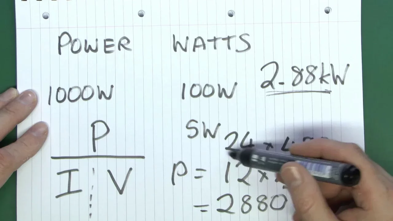
- Why this video: This video introduces electrical variables—voltage (electrical pressure), current (charge flow rate), resistance (opposition to flow), and power—by drawing highly accessible analogies. Understanding these concepts is essential to avoid destroying expensive stepper drivers or under-powering your robot's motors.
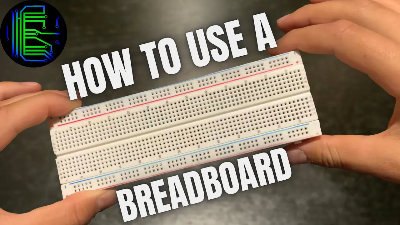
- Why this video: Solderless breadboards are the default medium for testing the circuit connections between your Arduino, power supplies, and A4988 drivers. This video shows how the internal rail system of a breadboard is connected, enabling you to build stable temporary circuits.
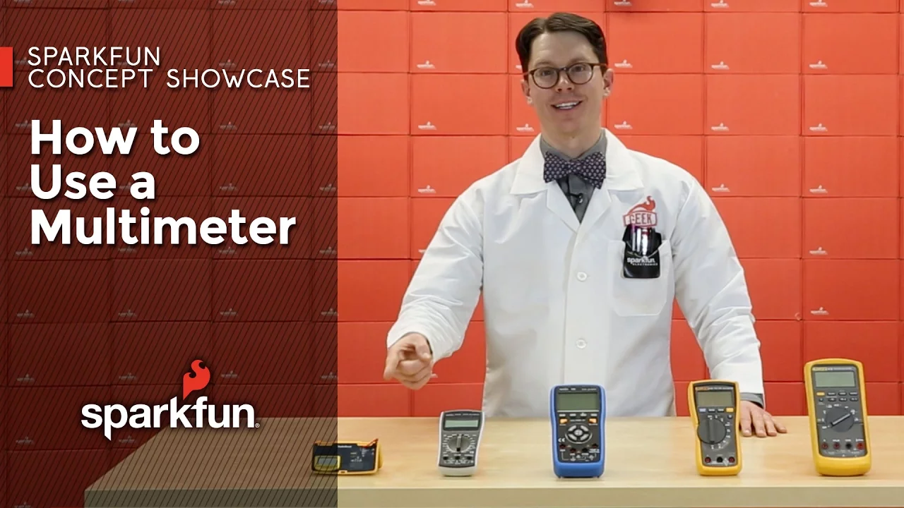
- Why this video: A digital multimeter (DMM) is a critical diagnostic tool for any hardware developer. This SparkFun guide details how to measure voltage drop, verify continuity across breadboard tracks, read resistance values, and check your power rail voltage levels.

- Why this video: This tutorial walks you through installing the Arduino Integrated Development Environment (IDE), selecting your board models, and running basic C++ program configurations. You will learn the layout of the code structure, focusing on the setup phase and loop executions.
Knowledge Checkpoint
- Can you define Ohm's law () and use it to calculate the minimum resistance needed to safely run a standard LED on a 5V Arduino pin?
- Do you know how to configure a multimeter to check if a wire has an internal break (continuity mode)?
- Can you explain the internal electrical differences between the power bus lines (vertical columns) and the terminal component strips (horizontal rows) of a breadboard?
- Are you able to compile and upload a basic
Blinksketch to an Arduino board and verify active serial board recognition?
Module 2: Stepper Motors and Winch Mechanics
In this module, you will learn the electro-mechanical principles of stepper motors (specifically bipolar NEMA 17 motors), interface them with an external DC power source via discrete A4988 driver chips, and calculate spool steps-per-millimeter metrics.
Recommended Videos
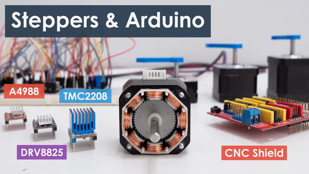
- Why this video: An in-depth overview of stepper driver wiring. It covers NEMA 17 internal coil alignments, logic signal inputs (
STEPandDIR), microstepping configurations, and how to calibrate the driver potentiometer to limit motor current and prevent overheating.
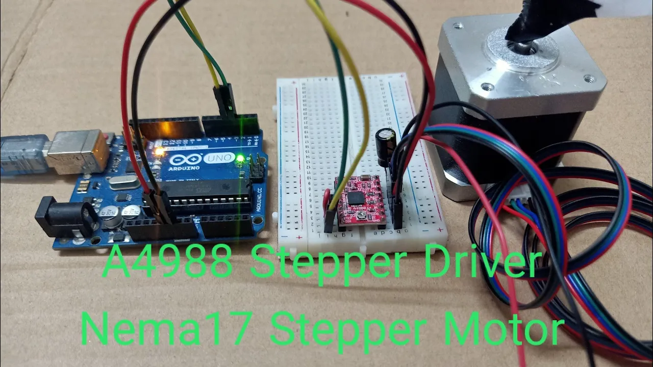
- Why this video: This practical guide walks you through wire-by-pin connections between a NEMA 17 stepper, an A4988 driver, and an Arduino Uno. It is an excellent step-by-step assembly reference for your workbench.
Gap Fill: Calculating Spool Steps-per-Millimeter
Because YouTube videos rarely cover the specific spool winding mechanics of wire and cable ropes, use this reference guide to calculate your steps-per-millimeter value.
1. The Fundamental Steps-per-Unit Formula
Standard NEMA 17 steppers feature a baseline resolution of (representing a step angle). When utilizing driver microstepping (configured via the driver's MS1, MS2, and MS3 pins), your effective resolution increases:
For example, on :
2. The Spool Conversion
The linear cable travel per output revolution of your winch corresponds to the spool circumference (). If your spool diameter is (in millimeters):
Therefore, the baseline linear step scale is:
3. The Cable Wrapping Deficit
For precision cable robots, remember that as a cable winds around a spool, it lays on top of prior layers. This increases the effective spool diameter (), causing the system to pull more cable per step than calculated. To minimize this error:
- Use thin, non-stretch synthetic line (like braided Dyneema/Spectra fishing line).
- Design wide, single-layer spools to prevent overlapping.
- If multiple layers are unavoidable, use this formula to approximate your steps-per-millimeter calibration:
Knowledge Checkpoint
- Do you know how to calculate your system's output resolution in steps-per-mm for a spool with a diameter running at ?
- Can you identify the correct wiring configuration for the dual internal coils of a 4-wire bipolar stepper motor using a multimeter?
- Why is it critical to tie the A4988
RESETandSLEEPpins together during normal operation? - Do you know how to adjust the small Vref potentiometer on an A4988 to limit current, based on your stepper motor's datasheet limits?
Module 3: Kinematics of 2D Cable-Driven Robots
This module covers the core math of your cable robot. You will learn to use Cartesian coordinate layouts and implement inverse kinematic equations to translate target coordinates into four distinct cable lengths.
Recommended Videos

- Why this video: This video introduces the 2-cable suspension plotter (Polargraph/drawbot), serving as an accessible stepping stone to 4-cable systems. It clearly illustrates how gravity, cable suspension, and top corner anchor positions coordinate to translate rotational movement into planar coordinates.

- Why this video: While many industrial robotics lectures rely heavily on complex Denavit-Hartenberg matrices, this video demonstrates how to solve 2D kinematic profiles using simple trigonometry and Pythagorean math.

- Why this video: This presentation by Dr. Pathak explains the structural physics of cable-driven parallel robots (CDPRs). You will learn how inverse and forward kinematics function in tension-only environments, where gravity or opposing cables must maintain tension to prevent system instability.
Gap Fill: Deriving 2D 4-Cable Inverse Kinematics
To fill the gap in specific 4-cable inverse kinematics tutorials, use the coordinate frame model below to write your coordinate translation program.
   (0,H) [Winch 1] ----------------------- [Winch 2] (W,H)
          |                                  |
          |               (x,y)              |
          |             [Effector]           |
          |                                  |
   (0,0) [Winch 4] ----------------------- [Winch 3] (W,0)
Let your CDPR frame have a width of and a height of . We place the origin at the bottom-left corner of the workspace.
- Winch 1 is located at
- Winch 2 is located at
- Winch 3 is located at
- Winch 4 is located at
If your pen end-effector is located at an arbitrary target coordinate , the required lengths of the four cables () from each corner winch can be calculated using the distance formula:
For any valid coordinate position within the frame boundaries ( and ), your microcontroller can calculate these four absolute lengths instantly to determine how much cable each winch must wind or release.
Knowledge Checkpoint
- For a frame (, ), what are the exact calculated lengths for all 4 cables when the end-effector is at the exact center ?
- How do the lengths change if you move the effector to the bottom-right coordinate ?
- Why must the sum of the tensions in all 4 cables remain positive? What happens mathematically if the effector moves outside the convex boundary of the winches?
- What is the difference between inverse kinematics (converting coordinates to cable lengths) and forward kinematics (converting cable lengths to coordinates)? Which is easier to compute in real time?
Module 4: Arduino Programming for Synchronized Motion
This module focuses on software development. You will learn how to write Arduino code to process coordinate commands over serial communication, compute kinematics on the fly, and synchronize the execution of all four motors using algorithms or libraries.
Recommended Videos
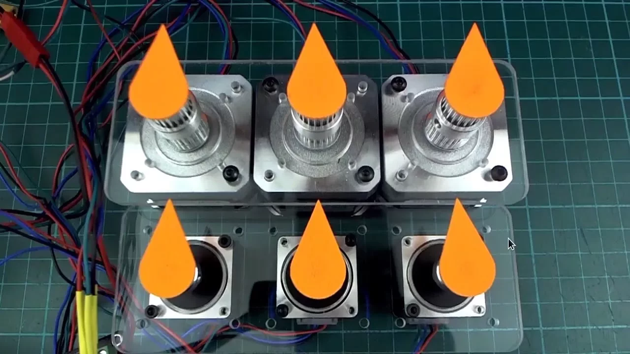
- Why this video: This video demonstrates how to run multiple stepper motors concurrently using low-level Arduino code. It explains how to coordinate steps across different axes so that all motors start and finish their movements at the exact same moment.

- Why this video: This video introduces the
AccelStepperlibrary's multi-stepper object configurations. It explains how to group multiple motors under a single control system to easily implement synchronized multi-axis motion.
- Why this video: This section of the course explains how to parse coordinate data sent from a PC to an Arduino via USB serial communication. You will learn how to implement structured delimiter strategies (like parsing strings such as
"X450,Y200\n") using native Arduino functions.

- Why this video: Bresenham's Line Algorithm is the standard algorithm used to draw straight lines across discrete pixels (or steps). This video provides an intuitive breakdown of Bresenham's derivation, illustrating how to sync multiple axes using integer math.
Gap Fill: Program Architecture for a 4-Cable CDPR
Since there is no video in the pool that integrates kinematics directly with the multi-stepper serial processing loop, implement the following program architecture:
#include <AccelStepper.h> #include <MultiStepper.h>
// 1. Define stepper motor pins AccelStepper motor1(AccelStepper::DRIVER, 2, 3); // (Type, StepPin, DirPin) AccelStepper motor2(AccelStepper::DRIVER, 4, 5); AccelStepper motor3(AccelStepper::DRIVER, 6, 7); AccelStepper motor4(AccelStepper::DRIVER, 8, 9);
MultiStepper steppers;
// 2. Define CDPR frame constants (in mm) const float W = 1000.0; const float H = 1000.0; const float STEPS_PER_MM = 40.74; // Calculated from your Module 2 spool setup
// Store current cable lengths (initialized at home position) long targetSteps[4];
void setup() { Serial.begin(115200);
// Set maximum limits motor1.setMaxSpeed(1000); motor2.setMaxSpeed(1000); motor3.setMaxSpeed(1000); motor4.setMaxSpeed(1000);
// Register steppers to MultiStepper controller steppers.addStepper(motor1); steppers.addStepper(motor2); steppers.addStepper(motor3); steppers.addStepper(motor4); }
void loop() { if (Serial.available() > 0) { // Parse target coordinates over Serial (Format: "X_val Y_val\n") float targetX = Serial.parseFloat(); float targetY = Serial.parseFloat();
// Boundary safety limits
if (targetX >= 0 && targetX <= W && targetY >= 0 && targetY <= H) {
  // Execute Inverse Kinematics calculations
  float L1 = sqrt(pow(targetX, 2) + pow(H - targetY, 2));
  float L2 = sqrt(pow(W - targetX, 2) + pow(H - targetY, 2));
  float L3 = sqrt(pow(W - targetX, 2) + pow(targetY, 2));
  float L4 = sqrt(pow(targetX, 2) + pow(targetY, 2));

  // Convert target cable lengths to absolute step values
  targetSteps[0] = L1 * STEPS_PER_MM;
  targetSteps[1] = L2 * STEPS_PER_MM;
  targetSteps[2] = L3 * STEPS_PER_MM;
  targetSteps[3] = L4 * STEPS_PER_MM;

  // MultiStepper handles speed calculations so all 4 winches finish simultaneously
  steppers.moveTo(targetSteps);
  steppers.runSpeedToPosition(); // Block and run motors

  Serial.println("OK"); // Ready for next coordinate
}
} }
Knowledge Checkpoint
- How does
MultiStepperensure that all motors finish their moves at the exact same moment, even if one motor has to step twice as far as another? - What is the role of a data delimiter (like
\nor a comma) in serial data streams? - How does parsing a coordinate as a
floatinstead of anintaffect calculation accuracy and system performance on 8-bit microcontrollers? - Can you explain why the
runSpeedToPosition()function blocks execution? What is the alternative if you need to read sensors during motion?
Module 5: Physical Assembly, Homing & Calibration
This final module focuses on physical integration. You will construct a stable CDPR frame, assemble the winch sub-assemblies, design the pen-holding end-effector, establish home coordinate references, and calibrate the system to ensure accurate plotting.
Recommended Videos
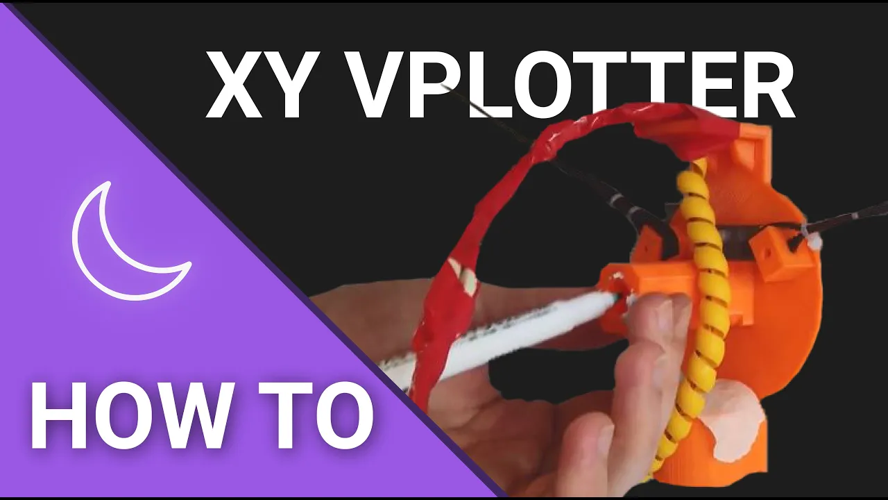
- Why this video: Outlines frame layout strategies, motor placement, and cable management techniques. It provides a blueprint for assembling a vertical suspension drawing machine, which you can easily expand into a 4-corner layout.
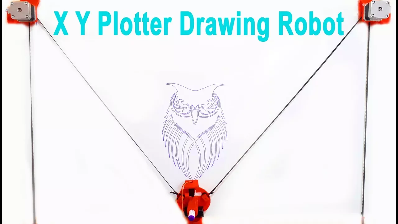
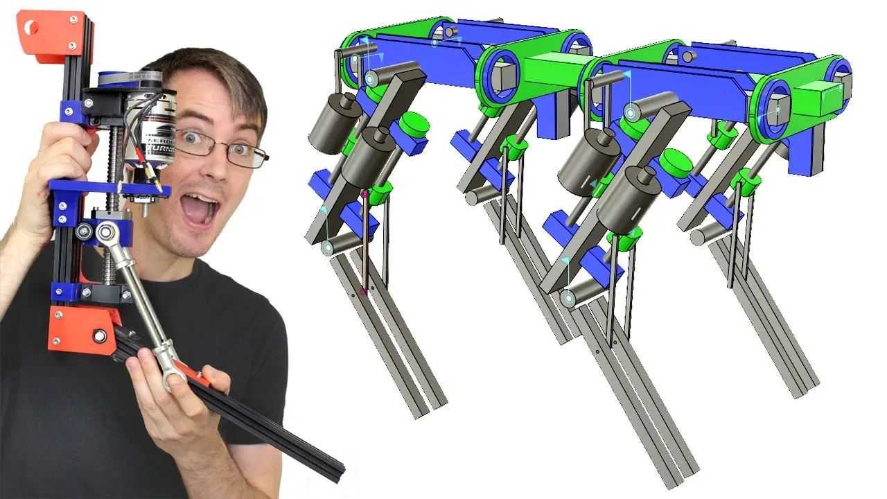
- Why this video: Focuses on the physical assembly of pen holders and mounting components. You will learn how to design a central, weighted end-effector that keeps the drawing pen stable during rapid movements.
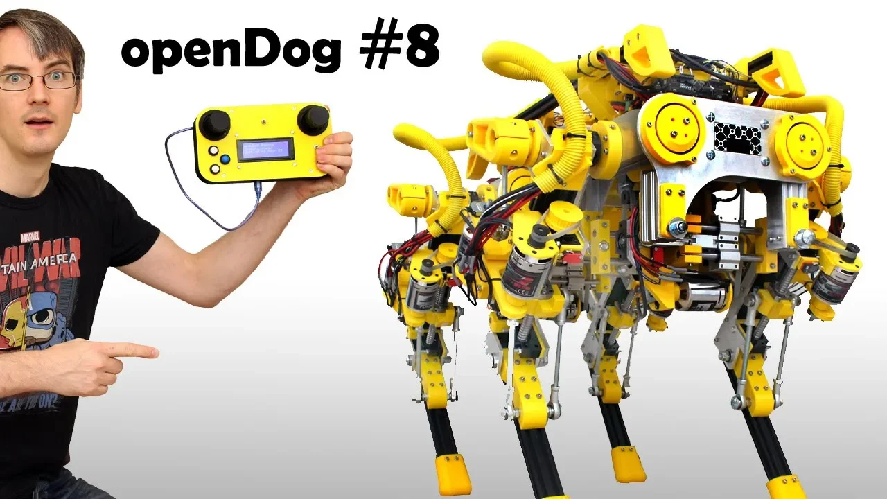
- Why this video: Establishing a physical coordinate reference is a fundamental requirement for any automated system. James Bruton demonstrates how to implement endstop limit switches to home a multi-axis system, which can be adapted to calibrate your CDPR's starting position.
- Why this video: This video covers the essential calibration steps for multi-actuator systems. Bruton goes through setting up homing offsets, configuring driver profiles, and adjusting feedback loops to ensure smooth, synchronized motion.
Gap Fill: CDPR Homing and Calibration Procedures
Unlike standard rigid CNC systems (which simply drive physical axes against microswitches), a CDPR has flexible cables. If you drive a cable robot against hard stops, you risk snapping the lines or burning out the motors due to excessive tension.
To safely calibrate your CDPR:
Step 1: Place effector on the physical center target calibration pin Step 2: Manually tension all four cables until they are taut Step 3: Power up the Arduino and run the calibration zeroing routine: - Current positions are set to home coordinates (W/2, H/2) - Target steps are set to the corresponding baseline lengths
- The Physical Reference Point: Mark a precise reference coordinate in the exact center of your workspace (e.g., coordinate for a frame). Install a small alignment pin or marking at this point.
- The Manual Homing Process:
- With the motors unpowered, hang your pen-carriage end-effector on the central alignment pin.
- Manually wind each winch spool until all 4 cables are taut and free of slack.
- Power on your Arduino. Your software will initialize this central position as the home location (, ). The code will then compute the starting step offsets based on the exact distances from the corners to this center point.
- Scaling Calibration:
-
Command the pen to draw a square.
-
Measure the actual drawn square using a ruler.
-
If the square measures wide, adjust your step scaling values:
-
Knowledge Checkpoint
- Why is it dangerous to home a 4-cable parallel robot by running all 4 winches inward until they hit mechanical endstops?
- What are the physical symptoms of running your system with too much cable tension? What are the symptoms of running it with too little (slack) tension?
- Can you explain how even a small, error in measured frame dimensions ( and ) can cause drawing distortion or line curving?
- How does adding weight (ballast mass) to the drawing head help stabilize planar movement and reduce cable vibration?
Course Map
Key People Index
- Dr. Pushparaj Mani Pathak (IIT Roorkee)
- Context: A leading robotics researcher specializing in the dynamics, workspace analysis, and control optimization of Cable-Driven Parallel Robots (CDPRs) used in large-scale automated construction.
- James Bruton (Robotics Designer & YouTube Educator)
- Context: A former toy designer and electrical engineer known for his open-source work on complex walking robots. His videos provide excellent, practical examples of multi-axis calibration and homing procedures.
- Paul McWhorter (Distinguished Electronics Educator)
- Context: A veteran high school engineering and programming instructor. His clear, methodical tutorials on basic circuits and Arduino programming are highly recommended for beginners starting their hardware journey.
Final Self-Assessment
Complete this comprehensive self-assessment before running your completed 2D cable-driven parallel plotting robot for the first time:
- Electrical Isolation Check: Your A4988 driver VMOT pins are connected to an external 12V DC power supply, and the GND lines of both the external supply and the Arduino are tied together to establish a common ground.
- Driver Potentiometer Calibration: The Vref voltage on all four A4988 drivers has been measured and adjusted to match the current limits of your stepper motors, preventing overheating.
- Winch Diameter Definition: The physical spool diameter has been measured with calipers, and the step calibration calculations () are loaded into the firmware.
- Workspace Limit Validation: The software parameters for frame width () and height () match the physical distances between your winches to within .
- Inverse Kinematics Code Compilation: Your firmware successfully compiles and runs, computing lengths () in real time without causing processor lag.
- Serial Parsing Handshake: Sending a coordinate string (like
"500 500\n") over the serial connection correctly triggers the parser and executes the inverse kinematics equations. - MultiStepper Sync Verification: Command the robot to execute a long diagonal move. All 4 motors must start and stop at the exact same moment.
- Manual Homing Setup: A central calibration pin has been installed, and the pen-carriage can be repeatably homed by manually tensioning the cables at this coordinate.
- Zero-Tension Slack Mitigation: While drawing near the frame corners, the opposing cables must remain taut enough to keep the pen holder stable and prevent drawing distortion.
- Calibration Factor Correction: Test squares drawn by your robot have been measured with a ruler, and any sizing errors have been corrected by adjusting your steps-per-millimeter scaling factors.