



![Aula 01 - Comandos Elétricos: Conceitos Iniciais [Treinar Serviços]](https://i.ytimg.com/vi_webp/r7ndxkyBaUQ/maxresdefault.webp)











![Una clase [rápida]🏃 sobre: ACOTACIÓN, (fundamentos básicos)✅](https://i.ytimg.com/vi_webp/55lFbV1fPx0/maxresdefault.webp)





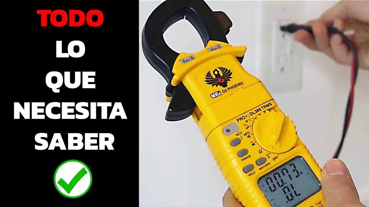

![Najlepszy multimetr [RS Elektronika] #141](https://i.ytimg.com/vi_webp/FYW8txXiuvk/maxresdefault.webp)







A digital multimeter (DMM) is an essential tool for electronics testing that measures voltage, current, resistance, and continuity; to measure voltage, connect the meter in parallel with the component and select the appropriate DC or AC range; to measure resistance, disconnect the component from any power source and connect the meter in parallel; to measure current, the meter must be placed in series with the circuit, requiring the probe to be moved to a dedicated current port; and for diode and continuity testing, the meter beeps when points are electrically connected or displays the forward voltage drop across a diode.
Multimeter Fundamentals: Voltage, Current, Resistance
Added:Basic electrical concepts: A conceptual understanding of what voltage (volts), current (amps), and resistance (ohms) represent.
Ohm's Law: The fundamental mathematical relationship between voltage, current, and resistance (V = I * R).
Circuit anatomy: The difference between open, closed, and short circuits, and how current flows through a loop.
AC vs. DC electricity: The distinction between Alternating Current (household power) and Direct Current (batteries), as multimeters have separate settings for each.
Series vs. Parallel measurements: Mastering how to physically insert the multimeter in series for current and in parallel for voltage measurements.
Circuit troubleshooting: Using measurements to diagnose electrical faults, such as unwanted voltage drops, short circuits, and blown fuses.
Advanced multimeter functions: Learning how to test diodes, transistors, capacitance, and frequency using specialized meter settings.
Introduction to breadboarding: Applying multimeter measurements to prototype, test, and debug low-voltage circuits with microcontrollers or analog components.
571.9K views3.3Klikes10:33Original Release: 2017-01-09
[music] One of the best tools you can own when beginning your journey into electronics is the digital multimeter, often called a DMM or simply a multimeter.
Inexpensive models, like this old RadioShack unit, offer just the basics. They can measure voltage, current, resistance, and continuity. Honestly, that is all you need for most circuit debugging and analysis.
As you move up in price, you will find better measurement accuracy and additional features.
For now, let us focus on how to use the basics so you can start debugging your own circuits.
Let us begin by examining the parts of a multimeter.
At the top is the LCD display. This is where measurement values are shown.
Most multimeters include a rotary knob or buttons to select what you want to measure. On this one, we can choose ranges for voltage, current, and resistance. There are also modes for diode testing and continuity.
The straight line with small dashed lines underneath represents direct current, or DC. The wavy line represents alternating current, or AC.
At the bottom of the multimeter are several ports for the probes.
The port labeled COM stands for common and is usually connected to ground or the negative node of a circuit.
Another port is typically labeled V and the omega symbol. This port is used to measure voltage and resistance. On this meter, it can also measure small currents, indicated by the milliamp symbol.
To measure larger currents, you must move the probe to a separate port. In this case, it is labeled 10 amps, which is the maximum current the meter can handle before blowing its internal fuse.
Most multimeter probes use standard 4 millimeter banana plugs.
There are several types of probes you may encounter.
Standard probes have pointed metal tips and are used by touching exposed wires, leads, or PCB traces.
Needle tip probes are helpful for very small pins and fine traces.
Alligator clips allow you to attach probes to wires or leads so your hands are free.
IC hooks are similar to alligator clips and are designed to grab the legs of integrated circuits.
Tweezer probes are useful for measuring small surface mount components like resistors.
One of the most common measurements you will make is voltage.
To measure voltage, the multimeter must be connected in parallel with the component.
This lets you measure the voltage drop between two points without interrupting the circuit.
In this example, we want to measure the voltage drop across a resistor.
We connect the positive probe to the node between the resistor and the LED. We connect the common probe to the node between the resistor and the negative terminal of the power supply.
I have built this circuit using a bench power supply set to 5 volts, with a resistor and LED connected in series.
To measure voltage, plug the probes into the COM and V ports. Typically, black is used for common and red for positive.
Set the dial to DC voltage and choose a range that is higher than what you expect.
Since we expect between 0 and 5 volts, selecting the 20 volt range works well.
With the circuit powered on, touch the probes to the resistor leads. The display shows about a 3 volt drop across the resistor.
If you accidentally swap the probes, do not worry. The meter will simply display a negative value.
Some multimeters, like this Victor model, support auto ranging. You simply select DC voltage and the meter automatically chooses the correct range.
Many multimeters can also measure AC voltage.
Before doing this, make sure your meter is rated for the voltage you are testing and that there are no exposed wires. Always use one hand when probing AC outlets to reduce the risk of current passing through your body.
Set the meter to AC voltage and a suitable range for around 120 volts if you are in the United States.
Insert the common probe into the neutral slot and the positive probe into the hot slot. You should see approximately 120 volts AC.
Next, let us measure resistance.
When measuring resistance, the multimeter is connected in parallel with the component.
The meter sends a small current through the component to determine resistance.
Always disconnect the component from any powered circuit before measuring resistance. Ideally, isolate it from other components to avoid inaccurate readings or damage to the meter.
Suppose we have a resistor with no visible label.
Set the meter to resistance mode and select the 200 ohm range. Touch the probes to the resistor leads.
If the display shows a single one, it means the resistance is higher than the selected range. Increase the range to 2 kiloohms, then to 20 kiloohms.
Now the meter reads about 3.3 kiloohms.
For a second resistor, the reading may appear as zero or very small on a high range. Lower the range to increase resolution. On the 200 ohm range, we see this resistor is about 47 ohms.
Auto ranging meters will display the correct value and units automatically.
Measuring current is also very useful, but it requires extra care.
To measure current, the multimeter must be placed in series with the circuit. This means you must break the circuit and insert the meter so current flows through it.
Never place a current meter in parallel with a circuit.
Doing so can create a short circuit and blow a fuse or damage the meter.
Many multimeters require moving the probe to a different port for current measurement.
Since we expect more than 200 milliamps, we move the positive probe to the 10 amp port.
In this example, we are measuring the current drawn by a motor.
Connect the positive terminal of the power supply to the positive probe. Connect the negative probe to the motor. The motor then connects back to the negative terminal of the power supply.
When the power is turned on, the motor spins and the meter shows about 200 milliamps.
Multimeters display average current. Fast current spikes from capacitors, inductors, or digital circuits may not be visible.
Oscilloscopes or specialized tools are needed for those measurements.
If you reverse the probes, the current will appear as a negative value. This does not harm the meter and simply indicates current direction.
After measuring current, always move the probes back to the voltage ports or remove them. Forgetting this step can easily cause a short circuit during later voltage measurements.
Another very useful feature is continuity and diode testing.
As with resistance measurements, isolate the component if possible.
The white band on this rectifier diode marks the cathode. Current generally flows from the anode to the cathode.
Set the meter to diode mode. Touch the positive probe to the anode and the negative probe to the cathode. The display shows about a 0.57 volt drop, indicating the diode is conducting.
If you reverse the probes, the display shows a one, meaning no current is flowing.
Continuity testing works in a similar way. The meter beeps when two points are electrically connected.
This beep is helpful because you do not need to look at the display while probing.
For example, if you have a TRRS cable and do not know which wire connects to which part of the plug, set the meter to continuity mode.
Touch one probe to the tip of the connector and probe each wire until you hear a beep. Mark that wire, then repeat for the rings and sleeve.
That covers the basics of multimeters.
Some models offer advanced features such as capacitance measurement, frequency measurement, temperature sensing with a thermocouple, minimum and maximum capture, and USB data logging.
Knowing how to use a multimeter allows you to probe, test, and understand circuits. I always keep one nearby because it is my first line of defense when debugging a design.
[music]
Up Next
23:51
Understanding Voltage, Current, Resistance, and Power in Electrical Circuits
@jwflame
589K views•2016-04-12

30:32
Ultrasonic Transducers: Resonant Frequency Measurement and Horn Design
@imajeenyus42
229.9K views•2017-02-22

12:45
Getting Started with Raspberry Pi: Setup and LED Blinking
@sparkfun
181.3K views•2014-05-22

33:39
How a Student's Question Saved a NYC Skyscraper from Collapse
@veritasium
22.8M views•2025-04-26
Related Study Plans & Knowledge Roadmaps
Structured learning paths in Engineering
engineering
Building Acoustic Levitators: Physics & Arduino
01The Physics of Sound and Standing Waves
02Piezoelectric Transducers and H-Bridge Drivers
03Arduino Programming: Generating 40 kHz Signals
+ 2 more learning modules
14h5 modules
Explore Roadmap
engineering
Building Peltier Cloud Chambers: Particle Tracks
01Cosmic Rays & Cloud Chamber Physics
02Thermoelectric Cooling (TEC) Fundamentals
03Custom Liquid-Cooling Loop Design
+ 2 more learning modules
18h5 modules
Explore Roadmap
engineering
Yagi-Uda Antennas: Modeling, Build & VNA Test
01Introduction to RF and Antenna Fundamentals
02Yagi-Uda Antenna Design Principles
03Antenna Modeling and Simulation in 4NEC2
+ 2 more learning modules
18h5 modules
Explore Roadmap
engineering
ECG Monitor Design: Op-Amps, Filters & Noise
01Electronics & Breadboard Basics
02Op-Amps and Instrumentation Amplifiers
03Bioelectricity and ECG Fundamentals
+ 2 more learning modules
18h5 modules
Explore Roadmap