Building a CNC Plotter: GRBL & G-Code Setup
Learning Goal: Design and construct a desktop CNC drawing plotter, configuring GRBL firmware, stepper motor drivers, and translating SVG graphics into G-code.
- Prerequisites: Basic knowledge of electronics (voltage, current, and polarity), familiarity with the Arduino IDE, and elementary vector design concepts.
- Estimated Total Study Time: 18 hours
Module 1: Introduction to CNC Mechanics & Motion Control
This module establishes the foundational physics and mechanics of computer numerical control (CNC) systems. You will study how Cartesian coordinates translate into physical motion, learn the core electromagnetism principles behind stepper motor rotation, and analyze different types of linear motion components.
Recommended Videos
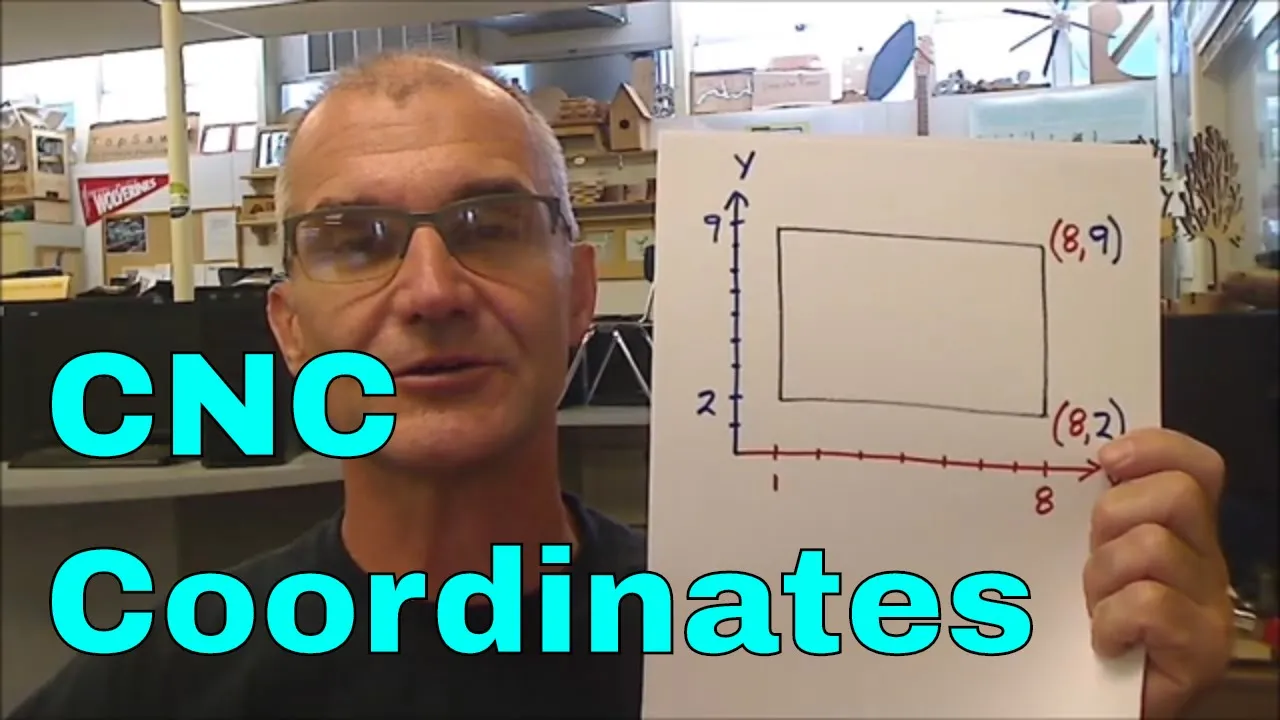
- Why this video is valuable: This video provides an intuitive breakdown of René Descartes' Cartesian coordinate system specifically mapped to CNC machines. It explains the relationship between the math quadrant system and physical toolpaths, teaching you how the coordinate frame dictates tool movement on the X, Y, and Z axes.

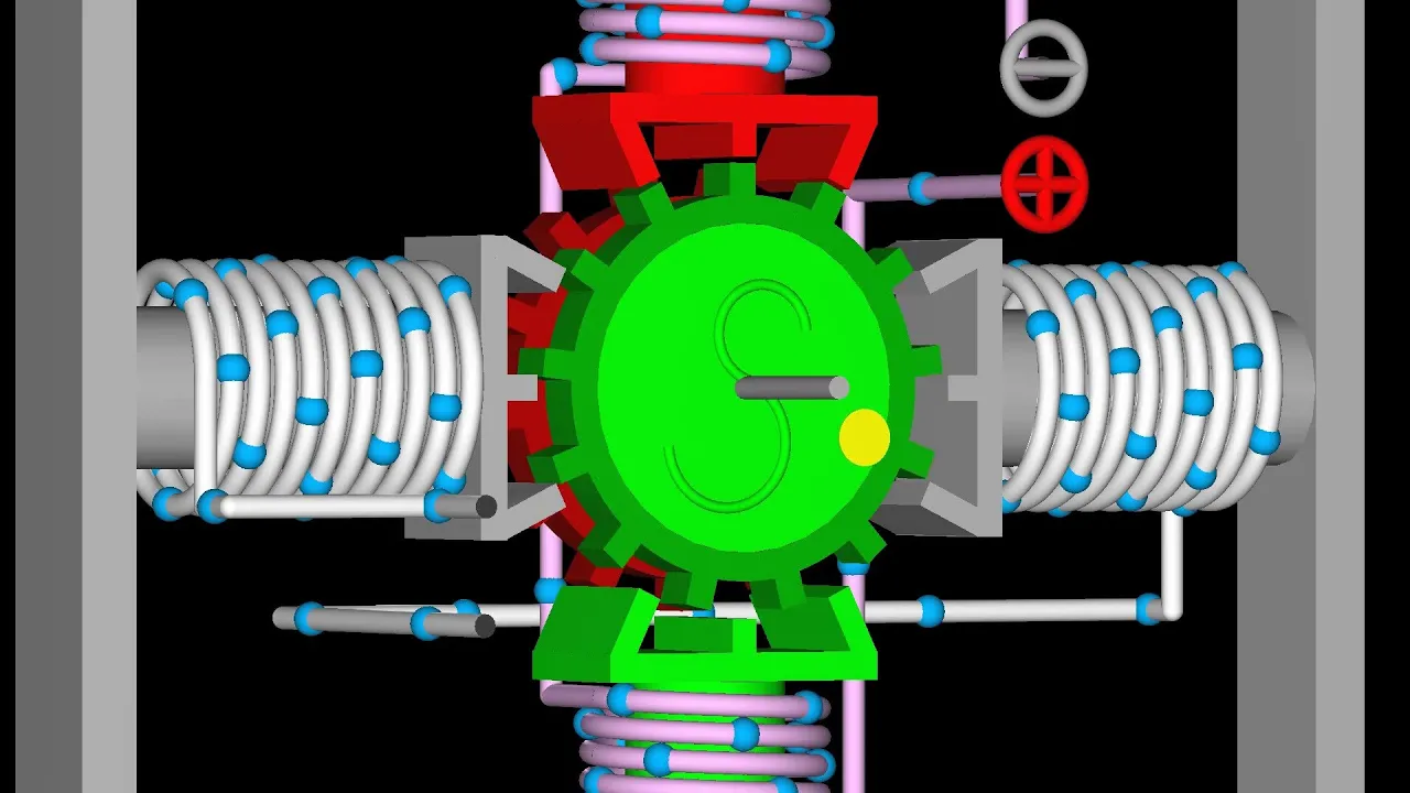
- Why this video is valuable: Stepper motors are the muscle of your CNC plotter. This 3D animation visualizes the internal construction of a hybrid stepper motor, detailing how electrical pulses selectively energize stator electromagnets to pull the permanent magnet rotor in precise, discrete angular steps.
- Why this video is valuable: A concise visual overview contrasting different stepper motor topologies (bipolar vs. unipolar vs. reluctance). It highlights how bipolar stepper motors—the kind standard on DIY CNCs—utilize two distinct H-bridge-driven coil phases to maximize holding torque.
Module 1 Knowledge Checkpoint
- Explain how Cartesian coordinate geometry (, , and axes) maps to a physical 3-axis CNC gantry.
- Describe how a stepper motor rotates in discrete steps rather than continuous rotation, detailing the role of the stator coils and magnetic rotor.
- Differentiate between a bipolar and a unipolar stepper motor, identifying why bipolar motors are preferred for high-torque motion applications.
Module 2: DIY Plotter Mechanical Assembly
This module covers the physical construction of a desktop drawing plotter. You will learn to weigh the mechanical advantages of different transmission systems (timing belts versus lead screws), evaluate belt drive designs, and walk through assembly steps for structural frame builds.
Recommended Videos
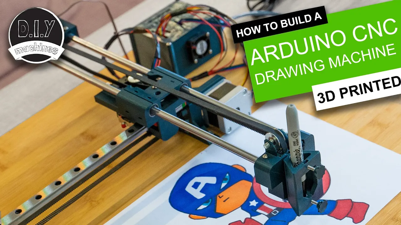
- Why this video is valuable: This video walks through the complete physical assembly of a desktop drawing plotter. It covers belt tensioning, linear rods, linear bearings, and structural alignment, providing an excellent step-by-step visual map of how a functional drawing machine is mechanically compiled from 3D printed components and metal rods.

- Why this video is valuable: To understand motion transmission, you must grasp pulley mechanical advantages. This video breaks down the physics of forces, loads, and rope/belt routing, which directly translates to choosing belt reduction ratios in mechanical design.
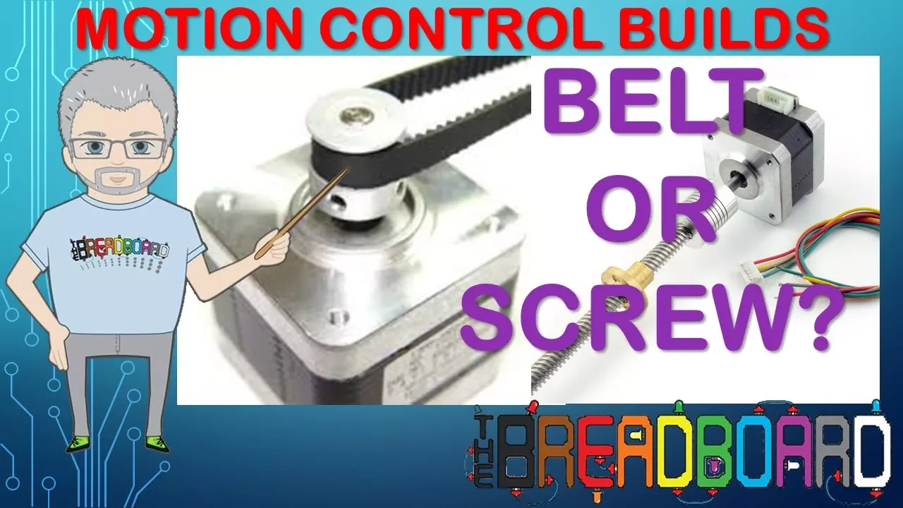
- Why this video is valuable: An essential comparative guide for CNC design. It details the fundamental tradeoffs between lead screw/ball screw systems (high mechanical advantage, high force, slow speeds) and timing belt drives (extremely fast travel speeds, zero backlash profiles, but limited torque), explaining why timing belts are ideal for pen plotters.
Mechanical Design Notes
Plotters rely on high speed and minimal inertia. A GT2 belt-and-pulley system is standard:
-
Pitch: (distance from the peak of one tooth to the next).
-
Backlash prevention: Timing belts engage teeth directly, preventing the slippage found in flat belts and the backlash found in low-cost threaded rods.
Timing Belt (2mm Pitch)
/ / / /
======================================= _Y_/ _Y_/ _Y_/ _Y_/ (GT2 Pulley teeth engagement)
Module 2 Knowledge Checkpoint
- List the primary mechanical differences, advantages, and disadvantages of lead screw transmission versus belt-and-pulley systems.
- Explain why a GT2 timing belt is optimal for a pen plotter application compared to standard flat or V-belts.
- Describe how to ensure linear rods and gantry frames are perfectly perpendicular ( alignment) to prevent drawing skew.
Module 3: Electronics: Arduino, CNC Shields & Stepper Drivers
This module covers the wiring, electrical integration, and power configuration of your plotter. You will learn to wire stepper motors, configure microstepping jumpers on an Arduino CNC Shield V3.0, and calculate and calibrate current limits via the driver reference voltage ().
Step-by-Step Wiring & Integration Guide
The electronics enclosure integrates a high-current DC power supply, an Arduino Uno micro-controller, a CNC Shield V3.0, and A4988 motor drivers. Incorrect assembly can instantly destroy your components. Follow this strict physical integration sequence:
[12V-24V DC PSU] -----> (Screw Terminals)
|
[CNC Shield V3.0] <=== Stacked ===> [Arduino Uno]
/ |
[A4988] [A4988] [SG90 Servo]
| | |
(X-Motor) (Y-Motor) (Pen Lift)
Step 1: Microstepping Jumper Configuration
Before installing your A4988 drivers into the CNC shield sockets, you must configure the microstepping jumpers. These physical jumpers pull the MS1, MS2, and MS3 driver pins high or low to determine step resolution.
- Locate the three pairs of jumper pins directly underneath each driver socket on the shield.
- Insert jumpers on all three pairs (MS1, MS2, and MS3) to enable 1/16 microstepping. This divides each step into 16 microsteps, yielding steps per full rotation (). This configuration drastically reduces vibration and increases plotting resolution.
Step 2: Mount Drivers and Shield
- Align and press the Arduino CNC Shield V3.0 onto the Arduino Uno headers. Ensure no pins are bent or skipped.
- Insert the A4988 stepper drivers into the X and Y axis sockets.
DANGER: Stepper drivers must be oriented correctly! On standard V3.0 CNC shields, the A4988 driver's small metal potentiometer adjustment screw must face away from the power input screw terminals. Look at the pin labels: match
GNDandDIRon the shield toGNDandDIRon the driver board. Plugging a driver in backward will instantly destroy both the driver and the Arduino upon power-up.
Step 3: Wire the Stepper Motors
- Connect your bipolar stepper motors to the 4-pin headers adjacent to each axis socket.
- Typical NEMA 17 wire pairings are: Coil A (Black/Green or Red/Blue) and Coil B (Red/Blue or Green/Black). Check your motor datasheet with a multimeter to verify coil pairs. Pairs must sit next to each other on the 4-pin header (Pins 1-2 form Coil A, Pins 3-4 form Coil B).
Step 4: Wire the External Power Supply
- DANGER: Never connect or disconnect stepper motors while the shield is powered! This causes high-voltage inductive spikes that immediately blow the driver output MOSFETs.
- Connect a 12V to 24V DC power supply (capable of delivering at least 5A) to the shield's main screw terminals. double-check polarity ( and ).
- Do not plug in the DC power supply to mains power yet.
Recommended Videos

- Why this video is valuable: This video walks through the hardware architecture of the CNC Shield V3.0 and A4988 driver, mapping out how the microstepping jumpers function and showing how control pins map to the Arduino Uno's internal registers.
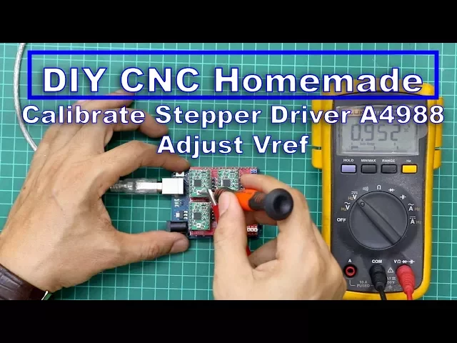
- Why this video is valuable: Essential guide on setting driver current limits. Uncalibrated drivers overheat and fail, or skip steps from lack of power. This video shows how to measure reference voltage () using a multimeter and adjust the onboard potentiometer.
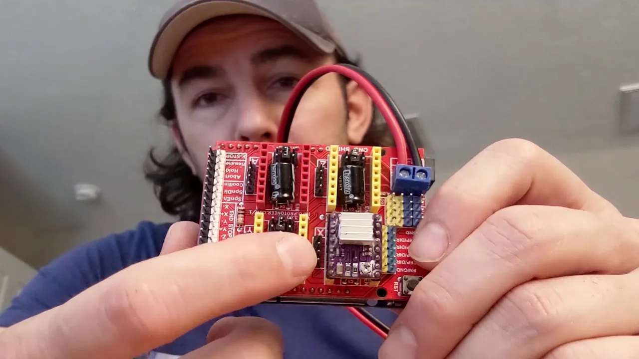
- Why this video is valuable: A quick reference pointing out critical failure modes during assembly. It reinforces the danger of powering up the system without motor loads connected and highlights proper thermal management (heatsink placement) on driver chips.
Step-by-Step Current Calibration ( calculation)
To protect your stepper motors and drivers, you must calibrate the driver's current limit. This is done by measuring the voltage () at the driver’s small potentiometer screw with a multimeter.
Mathematical Formula for A4988:
Most common red/green A4988 breakout boards utilize current sense resistors () valued at () or (). Let's assume your board has resistors and your NEMA 17 stepper motor is rated for a maximum current of . For safety and thermal longevity, we target of its rated current ():
Calibration Steps:
- Turn on the 12V/24V DC power supply (with stepper motors disconnected initially for basic reference setup, or carefully connected if adjusting under load). Keep the USB cable connected to the computer to power the logic side () of the driver.
- Set your digital multimeter to DC Voltage ( range).
- Connect the black probe of the multimeter to the negative power terminal (
GND) of the CNC Shield. - Touch the red probe of the multimeter carefully to the metallic top of the small A4988 potentiometer screw.
- Using a small ceramic screwdriver (or an insulated metallic screwdriver, taking care not to slip and short adjacent pins), slowly rotate the potentiometer screw until the multimeter reads exactly .
- Repeat this calibration for both X and Y axis drivers.
Module 3 Knowledge Checkpoint
- List the steps to set up microstepping on the CNC Shield v3.0, and explain how it affects drawing resolution.
- Calculate the correct reference voltage () for a motor driver with an of running a NEMA 17 motor limited to of current.
- Explain why powering a CNC shield without its stepper motors connected is highly discouraged, detailing the potential component failures.
Module 4: GRBL Firmware Flashing & Configuration
This module covers installing the GRBL control firmware on your Arduino and configuring its axis step variables. You will learn how to flash the .hex file via the Arduino IDE, connect using Universal Gcode Sender (UGS), and calculate the step resolution factors (, , ).
Recommended Videos
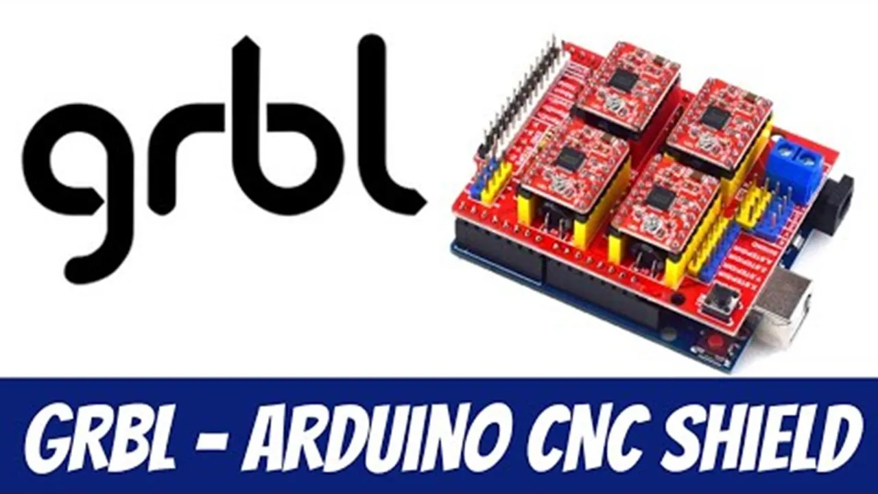
- Why this video is valuable: A quick setup tutorial for flashing GRBL onto an Arduino Uno. It shows where to download the source library from GitHub, how to import it into the Arduino IDE, and how to verify a successful compilation and upload.
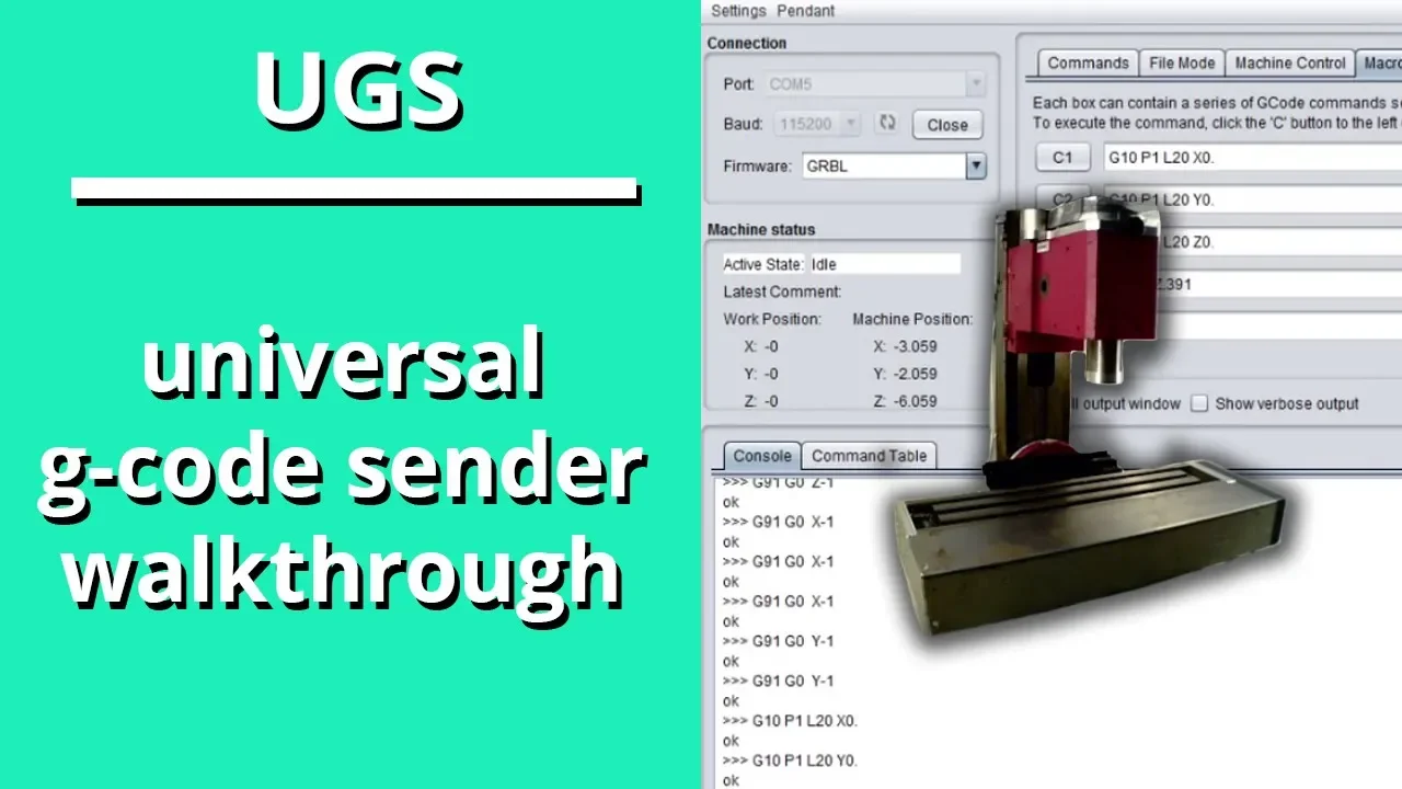
- Why this video is valuable: This video guides you through the interface of Universal G-Code Sender (UGS). You will learn how to configure connection settings (such as selecting COM ports and setting the baud rate to ), use the jogging controller, and send console commands directly to your CNC machine.

- Why this video is valuable: Deep dive into calibrating motion accuracy. This video explains why nominal step math might differ from physical results (due to belt stretch or machining tolerances) and teaches you how to measure and correct axis movement using a caliper.
Steps-Per-Millimeter Calibration Mathematics
The accuracy of your plotter depends on three core parameters:
$100: X-axis travel resolution (steps/mm)$101: Y-axis travel resolution (steps/mm)$102: Z-axis travel resolution (steps/mm)
Theoretical Formula (for Belt Drive Systems)
Where:
- Steps per revolution: (for a standard stepper motor).
- Microstepping factor: (if all three jumpers are installed under the driver).
- Belt Pitch: (for GT2 belt).
- Pulley Tooth Count: (standard GT2 pulley).
Applying these values:
This means you must enter $100=80 and $101=80 in the UGS terminal console.
Empirical Calibration Correction (Fine Tuning)
Due to manufacturing tolerances or belt tension variations, the actual drawn distance may vary slightly. To correct this, use this formula:
Example:
You command your plotter to draw a line. Using a digital caliper, you measure the physical line and find it is actually long. Your current $100 setting is set to the theoretical value of :
Send the update to GRBL by typing $100=81.22 in the UGS console and hitting enter.
Module 4 Knowledge Checkpoint
- Calculate the steps per millimeter for a stepper motor using microstepping connected to a lead screw with a pitch (lead) of per rotation.
- Write out the mathematical correction formula used if a commanded travel command produces a physical displacement of .
- Connect to your machine in UGS, query current EEPROM parameters by sending
$$, and identify the parameters for soft limits, homing, and travel resolution.
Module 5: Creating G-code from SVGs
This module teaches you how to translate 2D digital vector designs into mechanical motion commands (G-code). You will learn to prepare vector layers in Inkscape and use G-code generation tools to create paths for your plotter.
Step-by-Step Inkscape G-code Workflow
Standard CAD/CAM programs are designed for industrial routers and mills. For a pen plotter, we must use vector processing tools like Inkscape (version 0.92 or 1.0+) combined with plotting extensions to generate 2D pen toolpaths.
[Import Image/Raster] ---> [Trace Bitmap to Vector] ---> [Convert Object to Path] | [Export Plotter G-Code] <-- [Set Pen Up/Down Commands] <-- [Apply Gcodetools Extension]
Step 1: Document Settings
- Open Inkscape and access File > Document Properties.
- Set your default display units to mm and set the page dimensions to match the physical drawing area of your plotter (e.g., ).
- Move your vector artwork inside the page border. The bottom-left corner of this page corresponds to the home position of your plotter.
Step 2: Convert Text & Objects to Geometric Paths
CNC controllers cannot read raw text blocks or geometric circles directly. They only interpret explicit spatial vector lines.
- Select all items on your canvas (
Ctrl+A). - Select Path > Object to Path from the top menu. This traces vector strokes over the edges of your text and shapes.
- Confirm the change by selecting the Edit paths by nodes tool (
F2). Your vector graphics should now display distinct editing nodes along their lines.
Step 3: Configure Gcodetools Toolpaths
- Go to Extensions > Gcodetools > Orientation points. Set the orientation to match your document coordinates, defining unit measurements and setting the Z-depth parameters. Set the target depth ( axis displacement) to (since plotters only move in 2D space, height changes will be handled by our custom servo commands in Module 6).
- Go to Extensions > Gcodetools > Tool library. Select Cylinder or Cone and click apply. A green configuration box will appear on your canvas. Edit the text box values to configure the feed rate () parameter (e.g., for plotting).
Step 4: Export Plotter G-code
- Go to Extensions > Gcodetools > Path to G-code.
- Under the Preferences tab, input your output file directory path and name.
- Under the Path to G-code tab, ensure your coordinate system is configured correctly, then hit Apply. Inkscape will generate a
.gcodeor.ncfile containing a sequential list of Cartesian coordinates (, ) detailing the toolpaths.
Recommended Videos

- Why this video is valuable: This video walks through how to configure Inkscape's built-in Gcodetools extension. It details setting up orientation points, configuring the virtual tool library, and exporting clean G-code paths.

- Why this video is valuable: An in-depth masterclass on G-code syntax. It explains basic command functions, detailing what the machine physically executes when it receives coordinates linked with G0 (rapid travel), G1 (controlled linear feed), G2/G3 (arcs), or coordinate system modifiers like G90 (absolute positioning) vs G91 (incremental positioning).

- Why this video is valuable: Teaches vector tracing. If you start with a raster logo or hand-drawn sketch (PNG/JPG), this video demonstrates how to use Inkscape's "Trace Bitmap" engine to convert pixel grids into clean vector line loops suitable for plotting.
Comparative Guide: Core G-code Commands for Plotters
| Command | Name | Function in Plotters | Example Usage |
|---|---|---|---|
| G00 | Rapid Positioning | Moves the pen to new coordinate at max speed (pen lifted) | G00 X50.0 Y20.0 |
| G01 | Linear Interpolation | Lowers the pen and draws a straight line at a set speed | G01 X100.0 Y20.0 F1200 |
| G90 | Absolute Programming | Coordinates are read from the global origin | G90 |
| G91 | Incremental Programming | Coordinates are read relative to the pen's current position | G91 |
| M03 / M05 | Spindle On / Off | Repurposed to command the servo to lower (M03) or raise (M05) the pen | M03 S30 (Lower), M05 (Lift) |
Module 5 Knowledge Checkpoint
- Explain why a raw raster image (JPEG/PNG) cannot be run directly on a CNC drawing machine without being vectorized first.
- List the steps in Inkscape required to transform standard decorative text into a path composed of geometric coordinate nodes.
- Interpret this G-code file and describe the physical pen movements step-by-step:
G90
G00 X10.0 Y10.0
M03 S30
G01 X50.0 Y10.0 F1500
M05
G00 X0.0 Y0.0
Module 6: System Integration, Calibration & First Plot
This final module focuses on integrating the mechanical pen-lifting mechanism (servo motor), flashing custom servo-supporting GRBL firmware, running your first physical test print, and troubleshooting drawing errors.
Plotter Pen-Lift Servo Configuration
Standard GRBL firmware is written for industrial milling machines, where the axis is driven by a heavy stepper motor. Drawing plotters, however, use a lightweight hobby RC servo motor (such as an SG90) to quickly lift and lower the pen.
Because standard GRBL cannot directly control the 50Hz PWM signals required by hobby servos, you must flash a modified firmware fork, such as GRBL-Servo-Mio or GRBL-Servo.
          CNC Shield V3.0 Pinout for Servo
         +----------------------------------+
         |  [Spindle PWM] / [Z+ Limit] Pin  | <--- Signal (Orange/Yellow)
         |  [5V] Power Rail Pin             | <--- Power (Red)
         |  [GND] Power Rail Pin            | <--- Ground (Brown/Black)
         +----------------------------------+
Servo Wiring:
- Standard RC servo wires map to the CNC Shield V3.0 as follows:
- Signal (Orange/Yellow): Connect to the Z+ Limit Pin or Spindle PWM (D11) depending on your chosen GRBL-servo fork configuration.
- (Red): Connect to the shield's 5V auxiliary pins.
- GND (Brown/Black): Connect to any GND pin.
Tuning Pen-Lift PWM Settings:
Once flashed with the GRBL-Servo fork, your servo will respond to spindle speed commands (S parameters) to set its rotation angle:
- Pen Up Command:
M05or a low PWM value likeM03 S10(pulls the servo arm up to lift the pen off the paper). - Pen Down Command:
M03 S30(rotates the servo arm down to let the pen rest on the paper).
You can configure these limits in the GRBL settings or adjust them directly within your Inkscape G-code generation tools.
Recommended Videos

- Why this video is valuable: This video shows how to add an RC servo to a GRBL controller. It explains how standard GRBL's spindle speed control PWM (pin D11) can be repurposed to generate the 50Hz control signals needed to drive servo-based pen mechanisms.
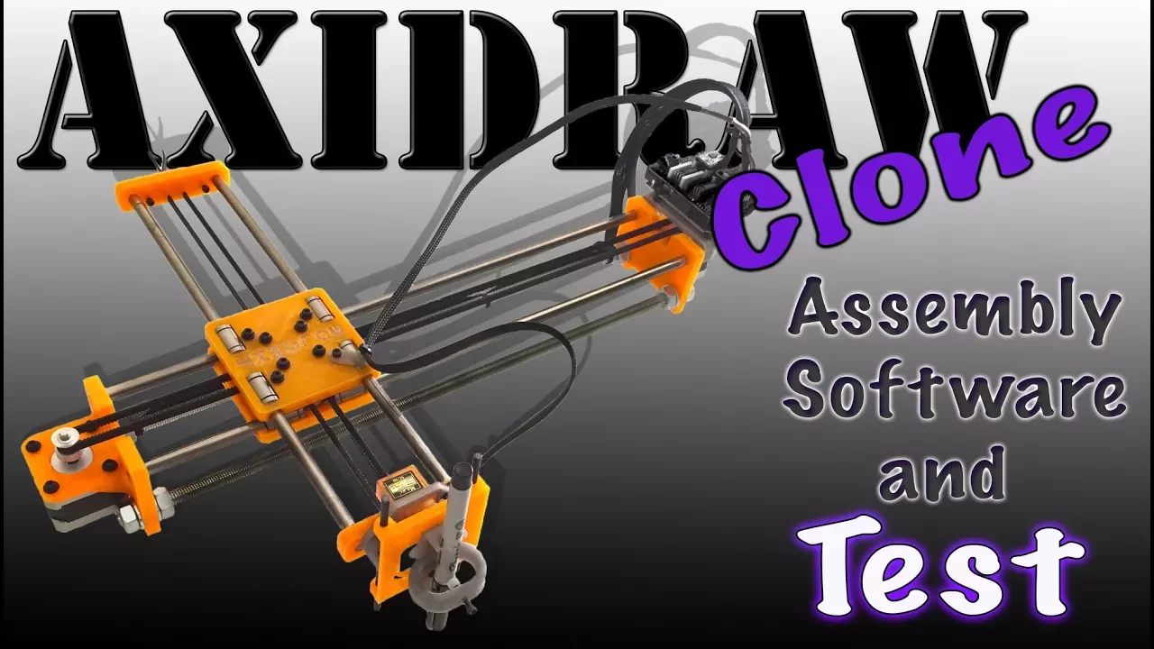
- Why this video is valuable: A comprehensive system integration tutorial detailing hardware assembly, wiring, flashing custom servo-controlling GRBL forks, and running a complete first plot.

- Why this video is valuable: Walks through the initial setup, calibration steps, and troubleshooting for your first drawing. It shows how to run simple square designs in Inkscape to verify dimensional accuracy, troubleshoot motor directions, and make sure the pen lifts properly.
Troubleshooting Plotting Artifacts
   Problem: Squelched Corners             Problem: Distorted Circles
     _____                                      _____
    /     \   (No sharp corners)               /     \
   |       |  <-- Mechanical slop/             |     | <-- Backlash or loose
    \_____/       loose timing belt             \___/      timing belt pulley
Problem 1: Drawn circles look like ovals or have flat sides.
- Cause: Mechanical backlash or a loose pulley set screw.
- Fix: Inspect the tiny grub screws securing the GT2 pulleys to the stepper motor shafts. If they slip, one axis will lag. Tighten all grub screws and ensure the timing belts are properly tensioned (they should have a low bass pluck sound when tapped, without bowing the gantry).
Problem 2: Hand-drawn lines are wavy or vibrate.
- Cause: The stepper motors are drawing too much current, causing high vibrations, or your pen holder mechanism has mechanical play.
- Fix: Slightly lower your driver current limits. Ensure the pen is mounted securely in its carriage with no wiggle room.
Problem 3: The pen drags across the page during travel transitions.
- Cause: The servo lift mechanism is misconfigured, or the response delay is too low.
- Fix: In your G-code generator, increase the dwell/delay command (
G04 P0.5— pause half a second) after pen-lift instructions (M05). This gives the servo arm enough time to lift before the carriage starts traveling.
Module 6 Knowledge Checkpoint
- Detail how to wire an SG90 servo motor to an Arduino Uno CNC Shield V3.0 for pen-lifting control.
- Explain why standard GRBL firmware must be replaced with a modified "GRBL-Servo" fork to run hobby RC servos.
- Diagnose a drawing where corners look rounded rather than sharp, listing two potential mechanical causes and how to resolve them.
Course Map
Key People Index
- René Descartes: French mathematician who invented the Cartesian coordinate system (, , ), forming the geometric basis for all modern CNC machining coordinates.
- The DIYMachines Team (@DIYMachines): Open-source hardware designers who created popular 3D-printable drawing robots, making mechanical assembly accessible to beginners.
- James Dean (@JamesDeanDesigns): Educator on CNC motion calibration, known for breaking down calibration equations and measuring techniques for physical machines.
- The MrInnovative Team (@MrInnovative): Prolific open-source maker known for designing compact Arduino-based drawing machines and providing practical engineering tutorials.
Final Self-Assessment
Complete this comprehensive self-assessment before running your plotter for the first time:
- Coordinate Direction: With the machine connected to UGS, test-jog the X and Y axes. Does travel right, and does travel away from you? If not, reverse the axis directions using the
$3setting in GRBL. - Current Driver Tuning (): Have you verified and set the current limits on both stepper motor drivers to protect the motors and driver chips?
- Stepper Motor Connections: Are all stepper motor connectors securely plugged in, and have you verified you are not unplugging them while the system is powered?
- Belt Tensioning: Are the timing belts properly tensioned on both axes with no visible slack, and are all pulley set screws tightened securely?
- Firmware Configuration: Have you successfully flashed the custom GRBL-Servo fork and verified that your PC can communicate with it at a baud rate?
- Travel Precision: Have you calculated and verified your steps per mm settings (
$100,$101) to make sure a command translates to exactly of physical movement? - Pen-Lift Integration: Does sending
M03 S30lower the pen carriage, and does sendingM05raise the pen safely clear of the page? - Vector conversion: Have you converted all text elements and objects in your SVG file into path geometries using Inkscape before exporting the G-code?
- G-Code Commands: Have you verified that your exported G-code contains appropriate travel feed rates and uses absolute positioning coordinate values (
G90)? - Physical Alignment: Have you squared your plotter's linear guide rails to prevent skewed, non-perpendicular drawings?