

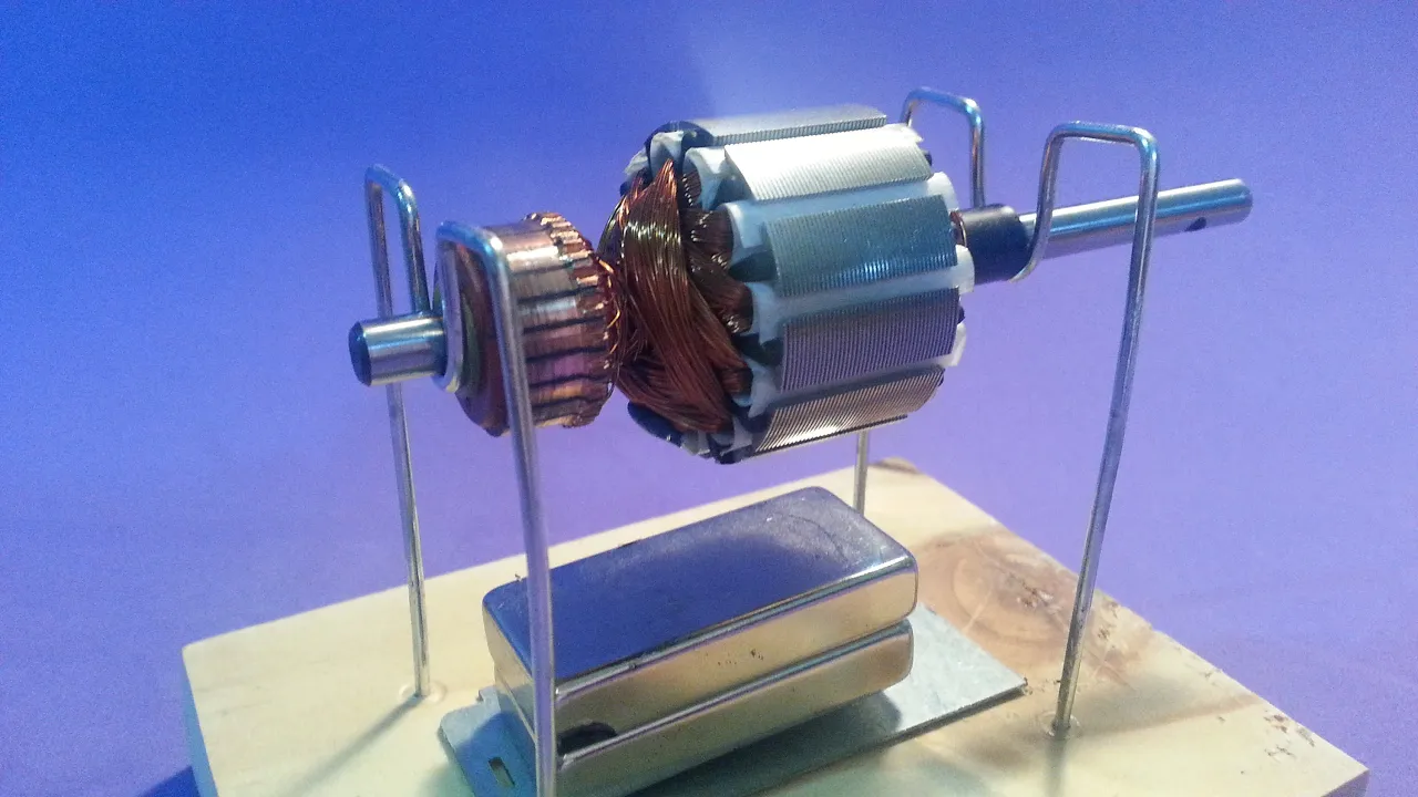





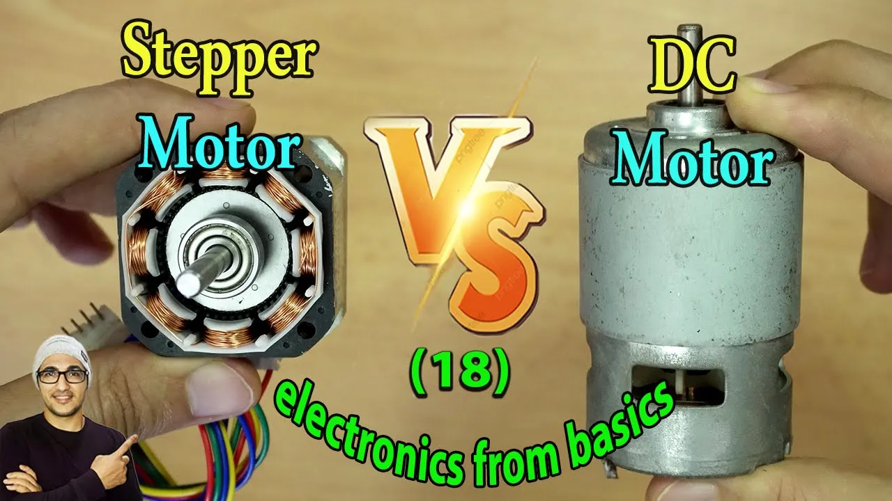




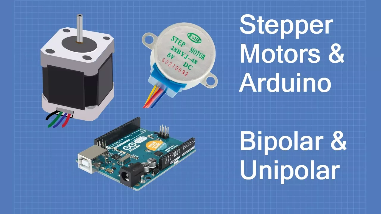
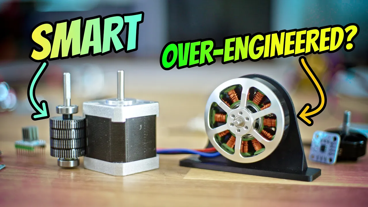

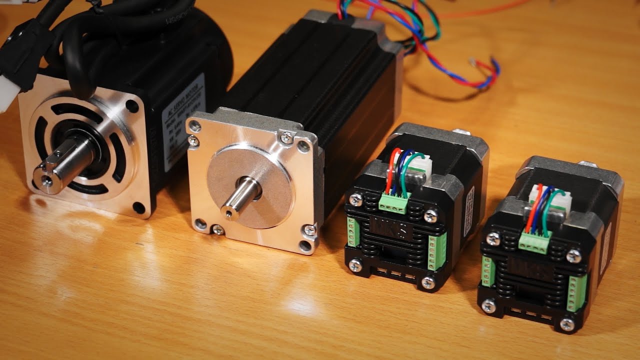


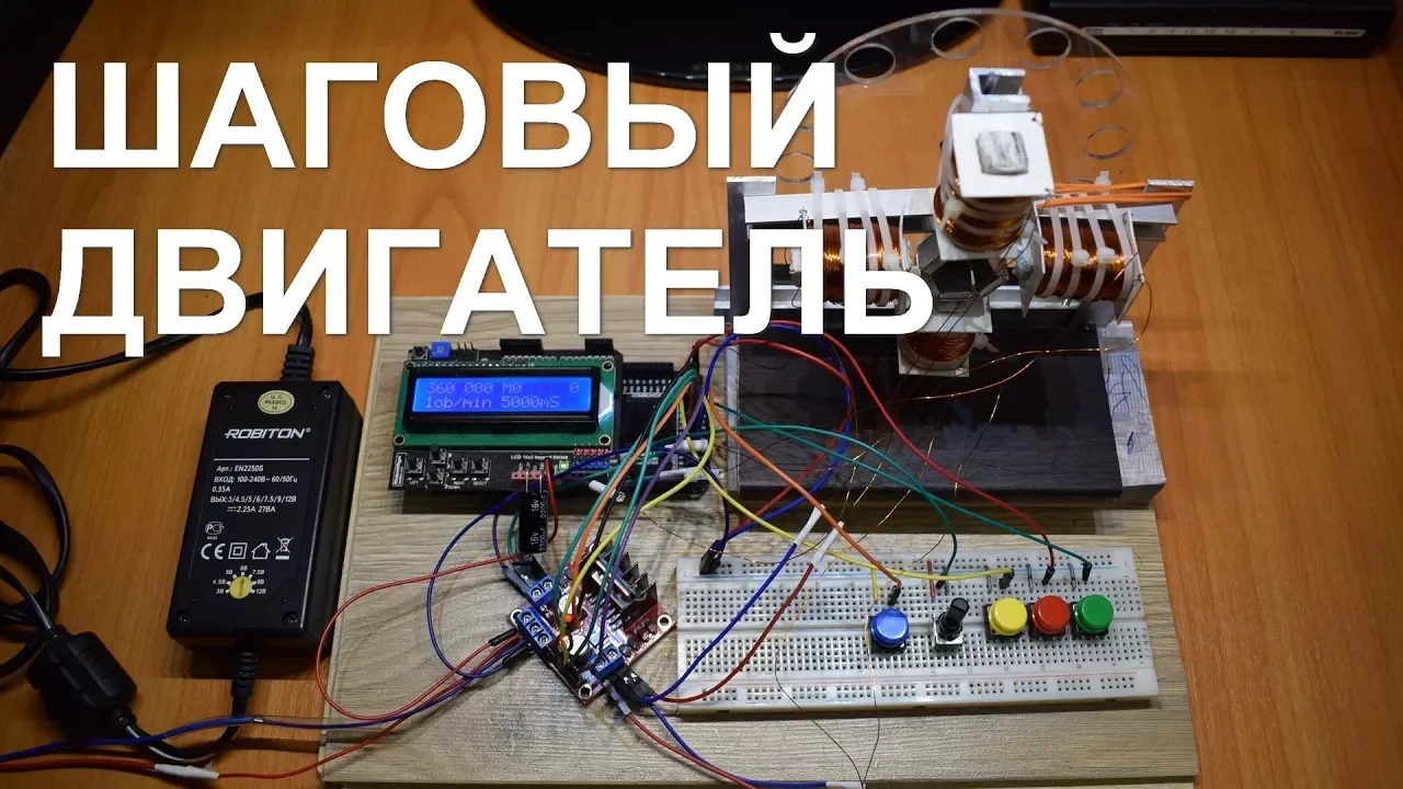


A stepper motor is a brushless DC electric motor that converts electrical pulses into precise mechanical shaft rotation, where each pulse produces one step of rotational motion; it operates through three step modes—full step (24 steps for full rotation at 15° increments), half step (48 steps at 7.5° increments), and micro stepping (120 steps at 3° increments)—with the driver controlling step angle and speed by switching field coils in specific sequences to achieve accurate positioning.
Stepper Motor Working Principle: 3D Animation Guide
Added:Fundamentals of electromagnetism, specifically how passing an electric current through a coil generates a magnetic field.
The principles of magnetic attraction and repulsion between permanent magnets and electromagnets.
Basic distinction between continuous rotation motors (like standard brushed DC motors) and incremental motion control.
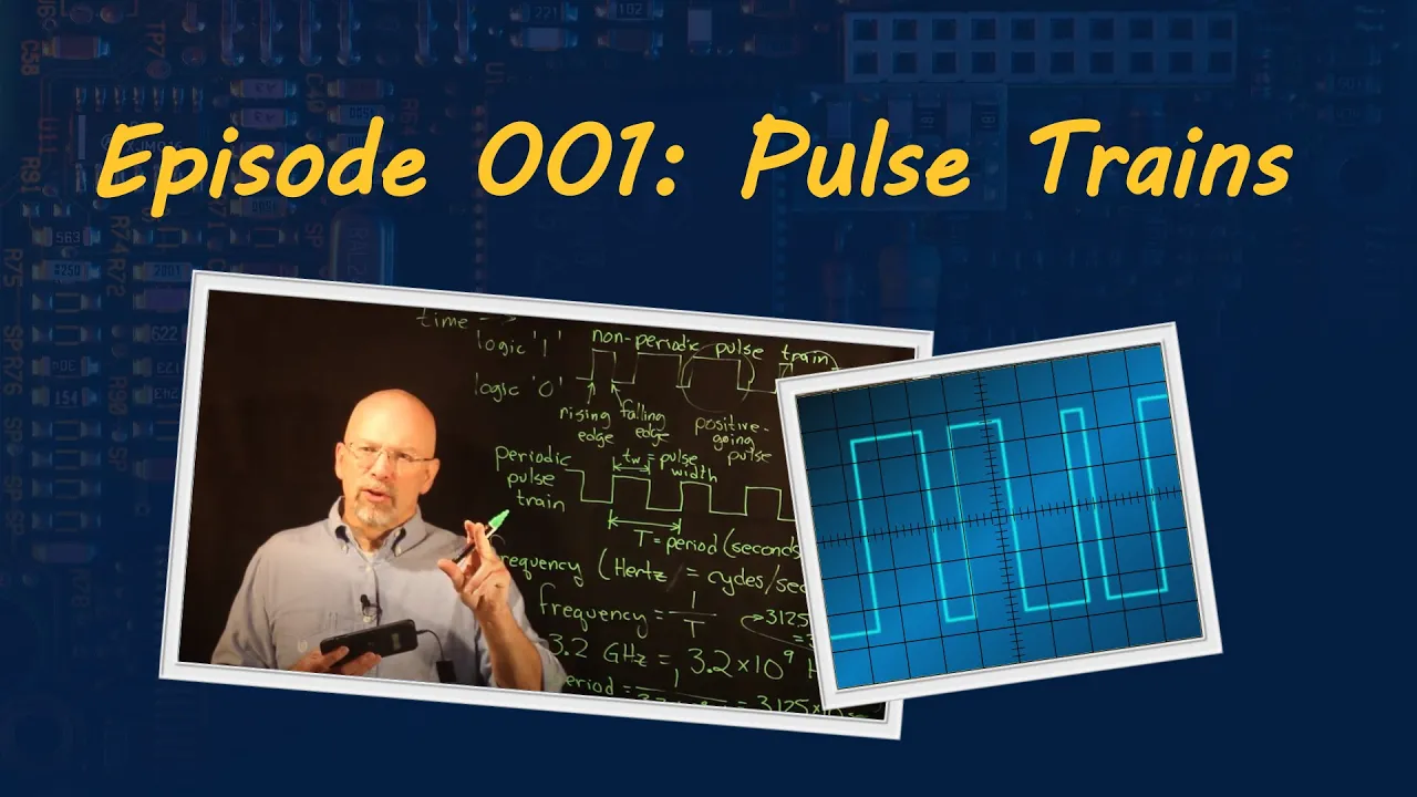
An understanding of digital signals, specifically how pulses and frequency translate to command signals.
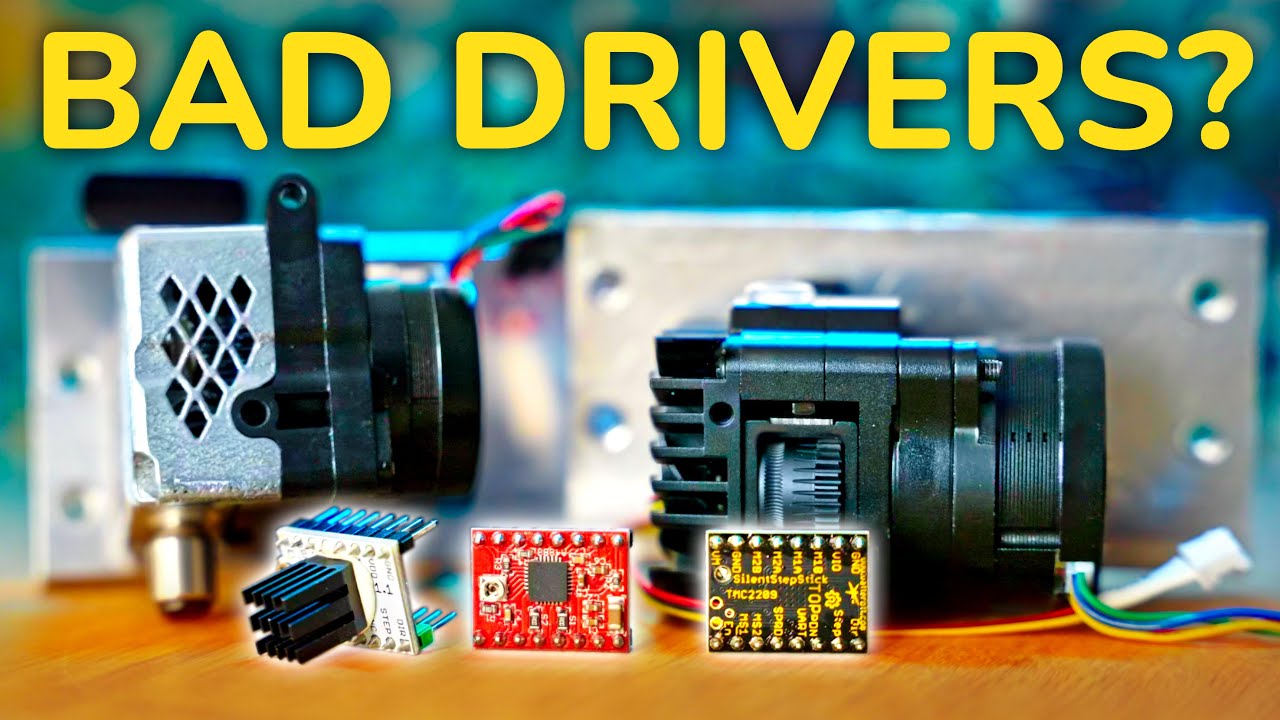
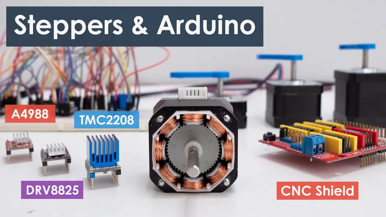
The function of stepper motor driver circuits and H-bridges, including how chips like the A4988 regulate phase currents.
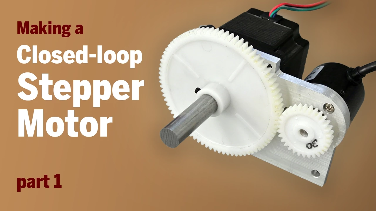
The integration of rotary encoders to transition from open-loop stepper control to closed-loop positioning systems.
Analysis of stepper motor performance limitations, such as resonance, holding torque, and torque degradation at higher speeds.
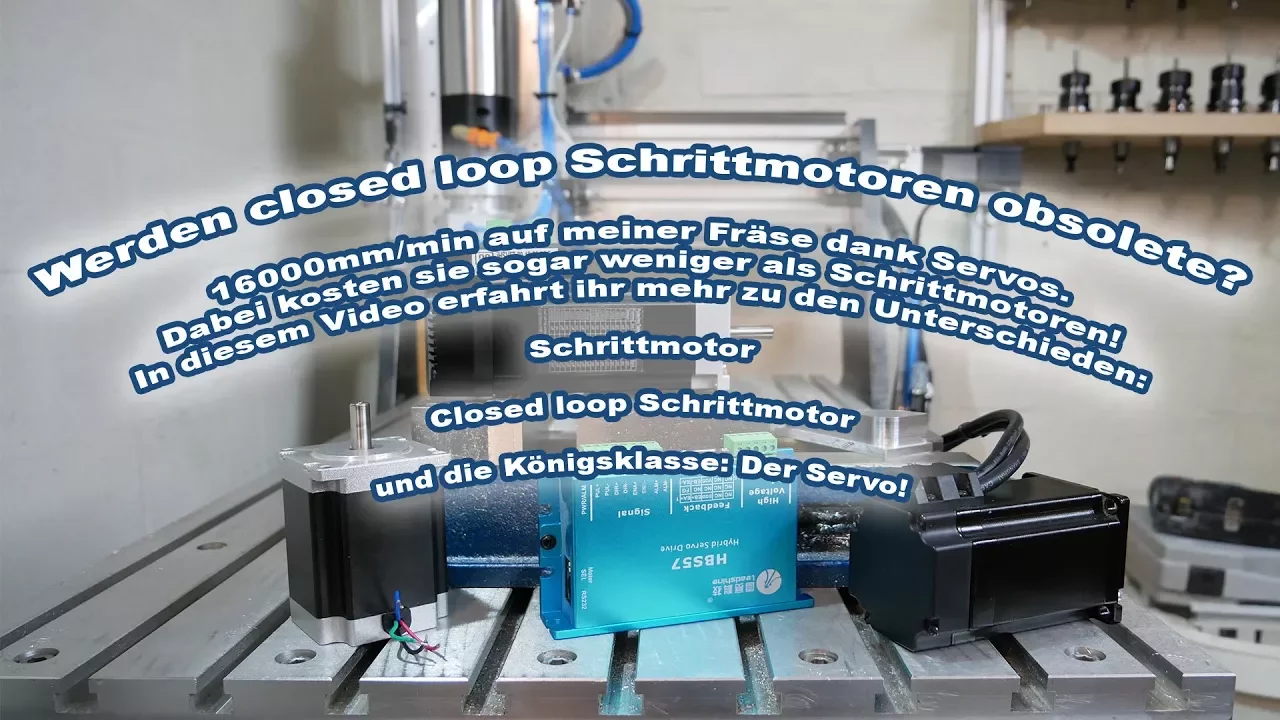
Comparative study of stepper motors versus servo motors in practical applications like CNC milling, 3D printing, and robotics.
176 views1likes6:05Original Release: 2022-02-23
stepper motor are classified as brushless dc electric motors that divide full rotation into an equal number of steps they are used in many applications in daily lives that include cd players electric tools and automation equipments as the name suggests each pulse of electricity produces one steps of rotational motion for this exercise we'll discover the basics of stepper motor technology beginning with the brushless dc motors [Music] unlike dc brush motor dc brushless motor do not utilize brushes to control current permanent magnet bonded directly to the rotor of the brushless dc motor create rotational motion as current power throws the starter a rotating magnetic field is formed by electrical pulse generated by a converter as the rotor turns a rotor position sensor provides feedback to the converter so the required start or field rotational sequence is maintained the change in sensor is at report back to the converter which continuous switches the fade to the windings to keep the motor turning the sequence is further explained here the hall effects and sultan on coils are energized by the converter the sequence is further explained here when the whole effects answer turn on creating the magnetic field to turn the rotor the sequence is repeated with the negative hall effect sensor and coils to continue rotation [Music] with the dc brushless motor being the foundation of stepper motor led look at how stepper works stepper motor also named because each pulse of electricity turns the motor one step a simple stepper motor system is comprised of our elements the user interface allows the operator to input motion parameters such as speed distance and directions example at an interface would be programmable logic controller or data entry terminal the number of steps the motor turns is equal to the number of pulse transmitted to the driver the stepper motor is a brushless electric motor that converts pulse into mechanical shaft rotation each pulse moves the shaft those a fixed angle defined by the multiple tooth electromagnets arranged around a gear shaped motor [Music] stepper motor have three step modes of operation that includes full half and micro stepping the type of step made output to any stepper motor is dependent on the design the driver the driver also control both the step angle and speed of the motor by switching the field coils in a set sequence for full step made operation energizing each set of coils sequentially the rotor can be made to rotate or step from one position to the next by an angle determined by its step angle shaft rotation is achieved by energizing both windings while reversing the current alternately switching coil abcd one coil at a time repeatedly will rotate the rotor in the forward direction in this example there are six step arrays on the rotor 60 degree apart 24 steps are required to make a full rotation at 15 degree increment for half step with the stepper motor resolution can be doubled by alternating the switching of coils half stepping occurs when one windings is energized and then two endings are energized alternately causing the rotor to rotate at half the distance switching coil in this combination will rotate in the reverse direction as you can see in this example 40 48 steps are required to make a full rotation at 7.5 degree increment [Music] microstrapping controls the current in the motor windings to a degree that further subdivides the number of positions between pools to achieve microsteps the coils are only partially energized as we apply a maximum voltage of 5 volt dc to coil and a maximum voltage of 0 volt dc to coil b motor position 1 will line up reducing the voltage to coil a and increasing voltage to coil b the rotor will begin to rotate in a clockwise direction and continue until the voltage is 0 at coil a and 5 at coil b this process continues at all coils within the starter to provide accurate positioning as you can see in this example 120 steps are required to make a full rotation at 3 degree increment [Music]
Up Next
7:47
Cartesian Coordinates for CNC: XY & XYZ Systems Explained
@ColfaxMath
3.6K views•2020-06-05

30:32
Ultrasonic Transducers: Resonant Frequency Measurement and Horn Design
@imajeenyus42
229.9K views•2017-02-22

54:16
Polymer Environmental Degradation: Mechanisms & Stabilization
@iit
1.8K views•2012-07-10

33:39
How a Student's Question Saved a NYC Skyscraper from Collapse
@veritasium
22.8M views•2025-04-26
Related Study Plans & Knowledge Roadmaps
Structured learning paths in Engineering
engineering
Building Acoustic Levitators: Physics & Arduino
01The Physics of Sound and Standing Waves
02Piezoelectric Transducers and H-Bridge Drivers
03Arduino Programming: Generating 40 kHz Signals
+ 2 more learning modules
14h5 modules
Explore Roadmap
engineering
Building Peltier Cloud Chambers: Particle Tracks
01Cosmic Rays & Cloud Chamber Physics
02Thermoelectric Cooling (TEC) Fundamentals
03Custom Liquid-Cooling Loop Design
+ 2 more learning modules
18h5 modules
Explore Roadmap
engineering
Yagi-Uda Antennas: Modeling, Build & VNA Test
01Introduction to RF and Antenna Fundamentals
02Yagi-Uda Antenna Design Principles
03Antenna Modeling and Simulation in 4NEC2
+ 2 more learning modules
18h5 modules
Explore Roadmap
engineering
ECG Monitor Design: Op-Amps, Filters & Noise
01Electronics & Breadboard Basics
02Op-Amps and Instrumentation Amplifiers
03Bioelectricity and ECG Fundamentals
+ 2 more learning modules
18h5 modules
Explore Roadmap