Building EMG Prosthetics: Arduino & 3D Print
Learning Goal: Design and prototype a low-cost, EMG-controlled prosthetic hand utilizing myoelectric sensors, an Arduino, and 3D-printed tendon-driven mechanical linkages.
Prerequisites
- Basic computer literacy (downloading and installing software).
- Access to a 3D printer (or a 3D printing service) and PLA filament.
- Basic electronics toolkit (breadboard, jumper wires, soldering iron is helpful but optional).
- No prior coding experience is required; we will build your programming foundation from scratch.
Estimated Study Time
- Total Estimated Hours: 28 hours (includes video instruction, hands-on physical prototyping, software debugging, and calibration exercises).
Module 1: Intro to Myoelectric Signals & Muscle Anatomy
In this module, you will explore how muscle contractions generate electrical signals (EMG) and learn the physiological basis of myoelectric control. Understanding how action potentials propagate across muscle tissue is critical for choosing optimal electrode placement on the forearm to capture clean, reliable signals for your bionic hand.
Recommended Videos
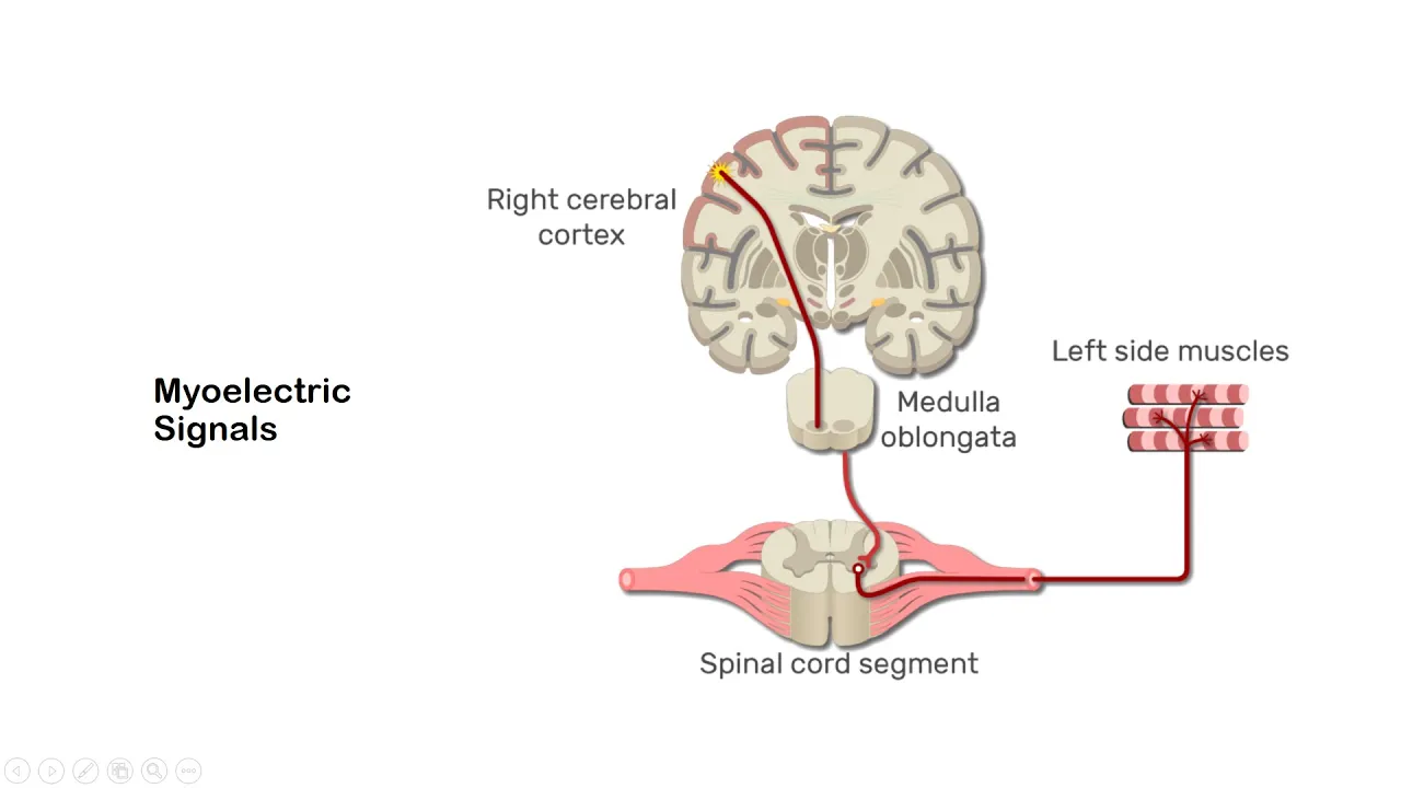
- Why this video: This video introduces the biological basis of myoelectric signals. It explains how ion exchanges across muscle membranes generate detectable surface potentials. This scientific groundwork is vital to understand what your sensors are actually capturing.
- Knowledge Checkpoint:
- Explain how muscle fibers produce biopotentials during a contraction.
- Distinguish between surface electromyography (sEMG) and needle EMG.
- Define the amplitude and frequency ranges typical of surface EMG signals.

- Why this video: This video provides clinical and anatomical depth regarding how motor neurons stimulate motor units. It bridges the gap between neural commands and actual mechanical muscle twitching, helping you strategically decide where to place skin electrodes over target muscle bellies.
- Knowledge Checkpoint:
- Define a "motor unit" and describe its role in EMG signal generation.
- Describe the phase relationship between motor unit action potentials (MUAPs).
- Identify which forearm muscles (e.g., flexor carpi radialis) are activated when making a fist gesture.

- Why this video: Although brief, this animated lesson visualizes the cellular action potential—explaining how sodium-potassium pumps open and trigger voltage shifts. This structural perspective allows you to visualize the micro-currents that your MyoWare sensor will amplify.
- Knowledge Checkpoint:
- Diagram how sodium and potassium ions flow across muscle cell membranes to trigger contractions.
- Explain how a loss of ionic balance affects the amplitude of myoelectric output during muscle fatigue.
Module 2: 3D Printing & Tendon-Driven Mechanical Design
In this module, you will study the mechanical architecture of 3D-printed bionic hands. Rather than using rigid metal gears, low-cost prosthetics utilize "tendon-driven underactuated mechanical linkages." You will study structural configurations, support material removal, and the mechanical physics of underactuated grasping.
Recommended Videos

- Why this video: A comprehensive, hands-on tutorial on processing 3D-printed prosthetic components. It teaches crucial techniques for cleaning print imperfections, clearing out internal tendon channels, and prepping polymer knuckles for assembly.
- Knowledge Checkpoint:
- Identify the safety precautions and tools needed for post-processing 3D-printed parts (e.g., reaming holes, removing support structures).
- Explain why clearing out internal channels is vital for low-friction tendon movement.
- Describe how layer-line orientation in FDM 3D printing affects structural stress limits in finger segments.
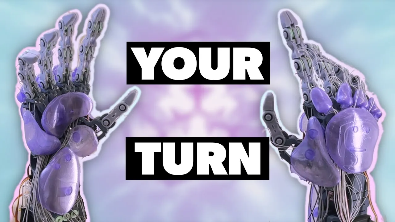
- Why this video: An elite showcase of building a highly articulated 3D-printed hand. This video breaks down the mechanical kinematics of modifying standard servos, routing lines, and using flexible joints as structural restoration springs.
- Knowledge Checkpoint:
- Distinguish between biological joints (IP, MCP, CMC) and their mechanical equivalents in a prosthetic hand.
- Explain how elastic joints function as a passive extension mechanism to open the fingers when the pull-tendon relaxes.

- Why this video: A high-level theoretical masterclass on underactuated systems. You will learn the mechanical physics of having fewer control inputs (actuators/servos) than degrees of freedom, which is the foundational design pattern of adaptive, conformable robotic grips.
- Knowledge Checkpoint:
- Define what makes a mechanical system "underactuated."
- Explain why underactuation is an advantage when grasping irregular three-dimensional objects.
Module 3: Arduino & EMG Sensor Hardware Foundations
Here, you transition to physical electronics. You will learn to safely set up your microcontroller, power your circuit safely, interface the analog pins of an Arduino Uno, and hook up a professional-grade muscle sensor (like the MyoWare) without creating ground loops or short circuits.
Recommended Videos

- Why this video: The ultimate introductory guide for microcontrollers. This video walks through installing the Arduino IDE, connecting your board, and running your first upload, ensuring your local development workspace is fully validated.
- Knowledge Checkpoint:
- Identify key hardware features of an Arduino Uno (e.g., ATmega328P, digital pins, analog pins, power pins).
- Successfully write, compile, and upload a basic sketch using the Arduino IDE.
- Differentiate between digital inputs (HIGH/LOW) and analog inputs (0 to 1023 resolution).

- Why this video: An incredibly direct tutorial demonstrating how to wire the popular MyoWare muscle sensor to an Arduino's analog input pin, place sEMG pads on skin surfaces, and plot the voltage output.
- Knowledge Checkpoint:
- Diagram the three core electrode connections: reference, end-muscle (muscle belly), and mid-muscle.
- Explain how to power the MyoWare sensor safely to prevent electrical shock and reduce 50/60 Hz mains power noise.
- Open the Arduino Serial Plotter to visualize changes in sEMG amplitude during muscular contraction.

- Why this video: A deeper hardware explainer demonstrating alternative raw EMG boards that require dual-rail power supplies (+9V, -9V, and Ground). It details how operational amplifiers (Op-Amps) and differential amplifiers reject common mode noise.
- Knowledge Checkpoint:
- Explain the concept of "Common Mode Rejection Ratio" (CMRR) in bio-amplifiers.
- Create a dual-battery power supply routing to achieve positive and negative voltage rails for analog conditioning circuits.
Module 4: Arduino Coding: Servos, EMG Thresholding, and Noise Filtering
This module focuses on software engineering. You will program your Arduino to read raw analog data, smooth out raw high-frequency fluctuations, establish dynamic activation thresholds, and translate muscle signals into smooth servo movements.
Recommended Videos
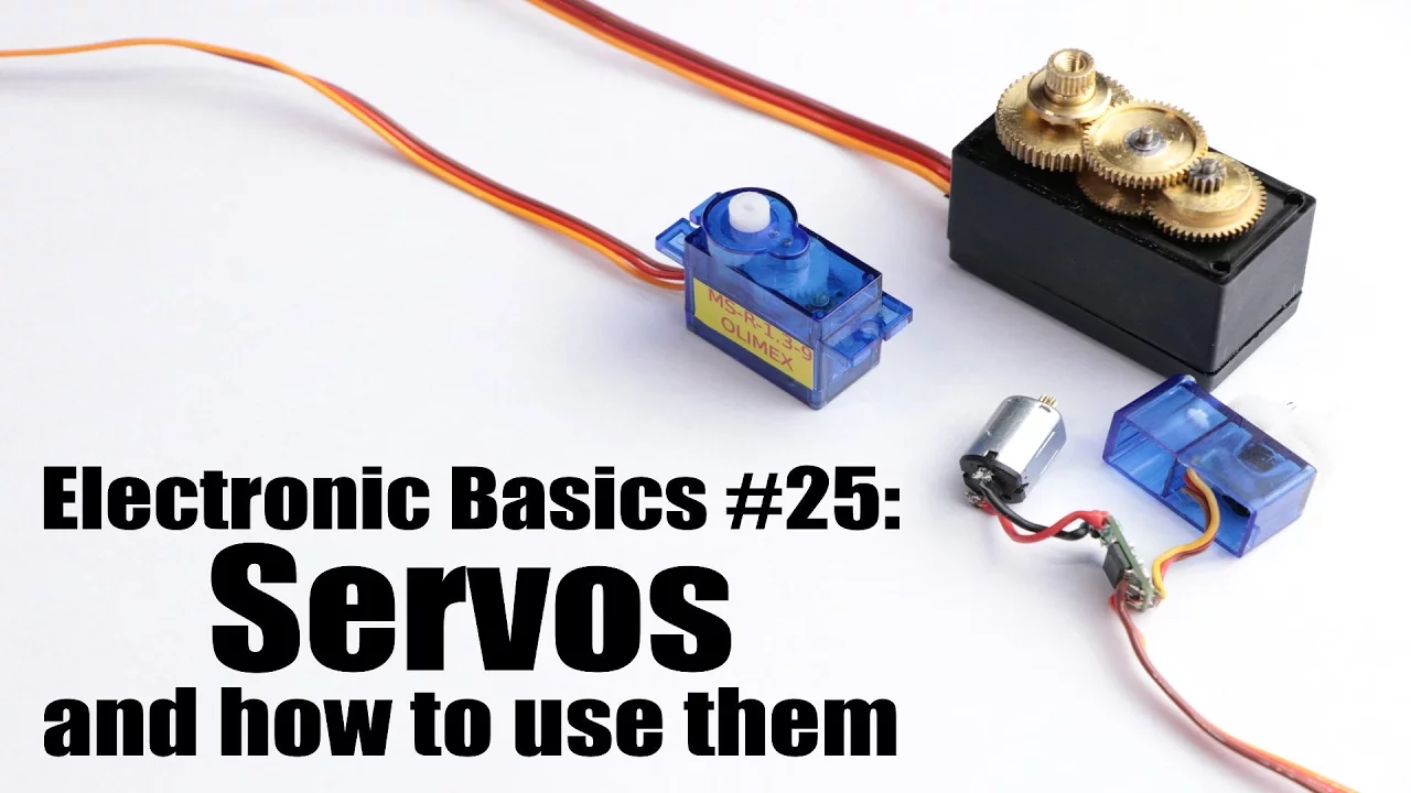
- Why this video: Clarifies how hobby-grade servo motors use Pulse Width Modulation (PWM) signals to control the internal potentiometer position loop. Essential for understanding how we command the physical tendon tensioners.
- Knowledge Checkpoint:
- Describe the standard PWM signal duty cycle needed to move a hobby servo from 0 to 180 degrees.
- Write basic code utilizing the official Arduino
<Servo.h>library. - Explain why powering a servo directly from the Arduino's 5V rail can cause system resets or brownouts.

- Why this video: Directly integrates the concepts of reading muscle sensor voltage levels and transforming those raw variables into servo motor rotation commands.
- Knowledge Checkpoint:
- Implement a conditional control loop (
if-elsestatement) to trigger servo movement when EMG levels cross a static limit. - Use the Arduino
map()function to proportionally control the servo angle based on muscle contraction intensity.
- Implement a conditional control loop (
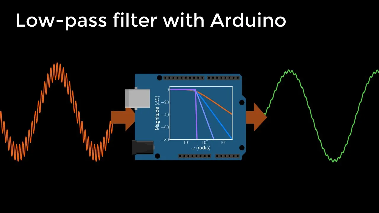
- Why this video: Introduces the math and code structures required to program a digital filter. Because EMG signals are inherently noisy, software low-pass filters prevent your servo motors from jittering randomly.
- Knowledge Checkpoint:
- Explain why raw ADC data requires digital smoothing in real-time embedded systems.
- Implement a first-order low-pass recursive formula in C++: .

- Why this video: While centered on datalogging, this segment introduces the algorithmic implementation of a "moving average filter" using circular buffers.
- Knowledge Checkpoint:
- Write a custom Arduino loop that continuously averages the last 10 raw analog readings to eliminate transient voltage spikes.
💡 Supplemental Coding Guide: EMG Threshold Calibration & Noise Filter
To address the common gap of writing clean signal processing algorithms, study and write this template code into your Arduino IDE. It sets up a rolling moving average filter and dynamic calibration process:
#include <Servo.h>
Servo tendonServo;
const int emgPin = A0; // Muscle sensor analog pin const int numReadings = 15; // Size of the smoothing window int readings[numReadings]; // Array for moving average int readIndex = 0; // Current index in array long total = 0; // Running sum int smoothedEMG = 0; // Filtered output value
int thresholdMin = 150; // Calibrated baseline rest value int thresholdMax = 600; // Calibrated max contraction value
void setup() { Serial.begin(9600); tendonServo.attach(9); // Connect servo PWM to digital pin 9
// Initialize all readings to zero for (int thisReading = 0; thisReading < numReadings; thisReading++) { readings[thisReading] = 0; }
// Perform dynamic calibration on boot (5 seconds) Serial.println("Relax muscles. Calibrating baseline rest..."); delay(1500); int baselineSum = 0; for(int i=0; i<100; i++){ baselineSum += analogRead(emgPin); delay(10); } thresholdMin = (baselineSum / 100) + 30; // set baseline slightly above average rest Serial.print("Baseline Min Set to: "); Serial.println(thresholdMin); }
void loop() { // 1. Calculate Moving Average to filter out high-frequency noise total = total - readings[readIndex]; readings[readIndex] = analogRead(emgPin); total = total + readings[readIndex]; readIndex = readIndex + 1;
if (readIndex >= numReadings) { readIndex = 0; }
smoothedEMG = total / numReadings;
// 2. Map filtered signal to servo rotation output (0-180 degrees) int servoAngle = map(smoothedEMG, thresholdMin, thresholdMax, 0, 180); servoAngle = constradictValue(servoAngle, 0, 180); // clamp bounds
tendonServo.write(servoAngle);
// Debugging output for visual plotting Serial.print("Raw_EMG:"); Serial.print(analogRead(emgPin)); Serial.print(","); Serial.print("Filtered_EMG:"); Serial.print(smoothedEMG); Serial.print(","); Serial.print("Servo_Angle:"); Serial.println(servoAngle);
delay(15); // standard control loop pacing }
int constradictValue(int val, int minVal, int maxVal) { if (val < minVal) return minVal; if (val > maxVal) return maxVal; return val; }
Module 5: Prosthetic System Assembly, Calibration & Testing
In this final module, you will physically compile all previous steps into a unified system. You will assemble your 3D-printed segments, route physical tendon lines, connect passive return springs, mount your servo motor horns, and execute a clinical calibration loop.
Recommended Videos
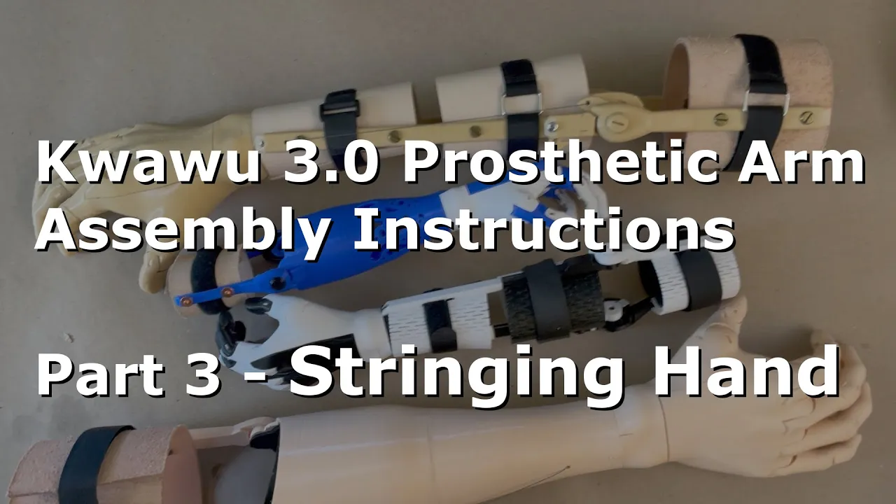
- Why this video: An exceptional procedural guide showcasing exactly how to thread, pull, tension, and secure high-strength dacron or monofilament lines through a 3D-printed prosthetic forearm structure.
- Knowledge Checkpoint:
- Describe how to lock the finger joints in a "fully open" baseline position during tendon tensioning.
- Identify optimal knots (such as bowlines or tensioner knots) to prevent tendon slippage under high tensile load.

- Why this video: Demonstrates the highly practical method of attaching thin elastic bands along the dorsal side of 3D-printed finger segments to act as a physical joint return spring.
- Knowledge Checkpoint:
- Explain why a reliable elastic joint-return mechanism is needed in single-tendon underactuated systems.
- Select appropriate elastic materials (e.g., elastic sewing cords, silicone bands) and bond them securely to PLA surfaces using CA glue.
- Why this video: Demonstrates practical mechanical linkages using standard nylon servo horns. It showcases how to attach structural wire or high-tension lines directly to rotating servo horns without stripping the delicate plastic output gears.
- Knowledge Checkpoint:
- Safely drill out holes on a nylon servo horn to match tendon diameters without weakening the structural integrity of the horn.
- Calculate the linear travel range of a tendon based on the radius of your mounting servo horn ().
⚙️ Step-by-Step System Assembly & Tensioning Guide
Because full system integration has historically limited video coverage, follow this step-by-step engineering SOP to complete your build:
- Clean print channels: Take a steel rod or guitar string and push it through the routing channels inside each finger segment to clear out layer anomalies, printing dust, and loose supports.
- Install the joint return cords: Cut strips of elastic cord. Glue the elastic cord along the back knuckles (dorsal side) of each finger using cyanoacrylate (super glue) and accelerator. When you fold a finger manually, the elastic cord should stretch and immediately pop the finger back open when released.
- Route the main pull-tendon: Securely tie a heavy knot at the distal fingertip print cavity using a non-stretch braided Dacron fishing line. Route the string down through the internal pathways of each joint, emerging at the base of the wrist.
- Mount the servo motors: Zero out your servo motors by uploading a temporary script driving them to . Install the custom 3D-printed tension brackets or nylon servo horns onto the splined output shaft.
- Attach and tension the lines: Ensure the hand is fully extended by the elastic bands. Pull the tendon lines taut until there is zero slack in the fingers. Tie off the lines to the furthest hole of your servo horn, and lock the knot using a drop of nail polish or super glue to prevent fraying.
- Integrate and Calibrate: Connect your MyoWare muscle sensor electrodes to your dominant arm, power up the Arduino with an external 6V power source (for the servo), and adjust your
thresholdMaxvalue to match your individual muscle contraction envelope.
Course Map
This map outlines the recommended sequential pathway through the curriculum modules.
Key People Index
- Paul McWhorter (@paulmcwhorter): Renowned systems engineer and electronics educator. His direct, zero-jargon programming tutorials provide the absolute reference path for physical computer-science basics.
- Will Cogley (@WillCogley): An open-source mechanical designer specializing in complex, low-cost biomimetic bionic hands and mechanical tendon linkages.
- Dr. Russ Tedrake (MIT): Pioneer of underactuated control systems and robotic locomotion theory at the MIT Dynamic Design Lab.
- James Bruton (@jamesbruton): Former toy designer and legendary robotics builder known for showing highly intuitive, low-cost mechanics for tendon linkages and servo attachments.
Final Self-Assessment
Complete this comprehensive checkpoint to verify your engineering and soft-skills competence:
- Explain how muscle contractions translate to millivolt potentials detectable on the skin.
- Determine optimal electrode placement over muscle bellies versus non-conductive bony regions.
- Correctly adjust slicing parameters (such as wall count and infill density) to print durable structural hand pieces.
- Post-process internal printed tendon paths to minimize mechanical friction.
- Wire an analog EMG sensor without creating a hazardous ground loop or brownout condition.
- Program a working moving average digital filter to clean high-frequency sensor noise.
- Implement calibration variables within your code to customize the activation envelope of your prosthetic hand.
- Rig a tendon line using monofilament/braided Dacron line with proper tension locking knots.
- Build a robust passive elastic joint return mechanism.
- Demonstrate a complete myoelectrically-controlled physical grip cycle (fist contraction maps directly to prosthetic grip close).