





















![Serwonapędy w przemyśle [Webinar] | Schneider Electric](https://i.ytimg.com/vi/Hle1-_TZi_A/sddefault.jpg)
A servo motor is a closed-loop system that combines a DC motor with control electronics to achieve precise angular positioning; it uses a potentiometer for feedback, where the control IC (KC 5188) compares the current position voltage against a target PWM signal (with a 20ms period and 1-2ms duty cycle) to drive the motor through an H-bridge, allowing rotation between 0° and 180°, and can be controlled using a microcontroller like Arduino or simpler circuits like a 555 timer; for continuous 360° rotation, the mechanical end stop and feedback potentiometer can be modified.
Understanding Servo Motors: How They Work & How to Use Them
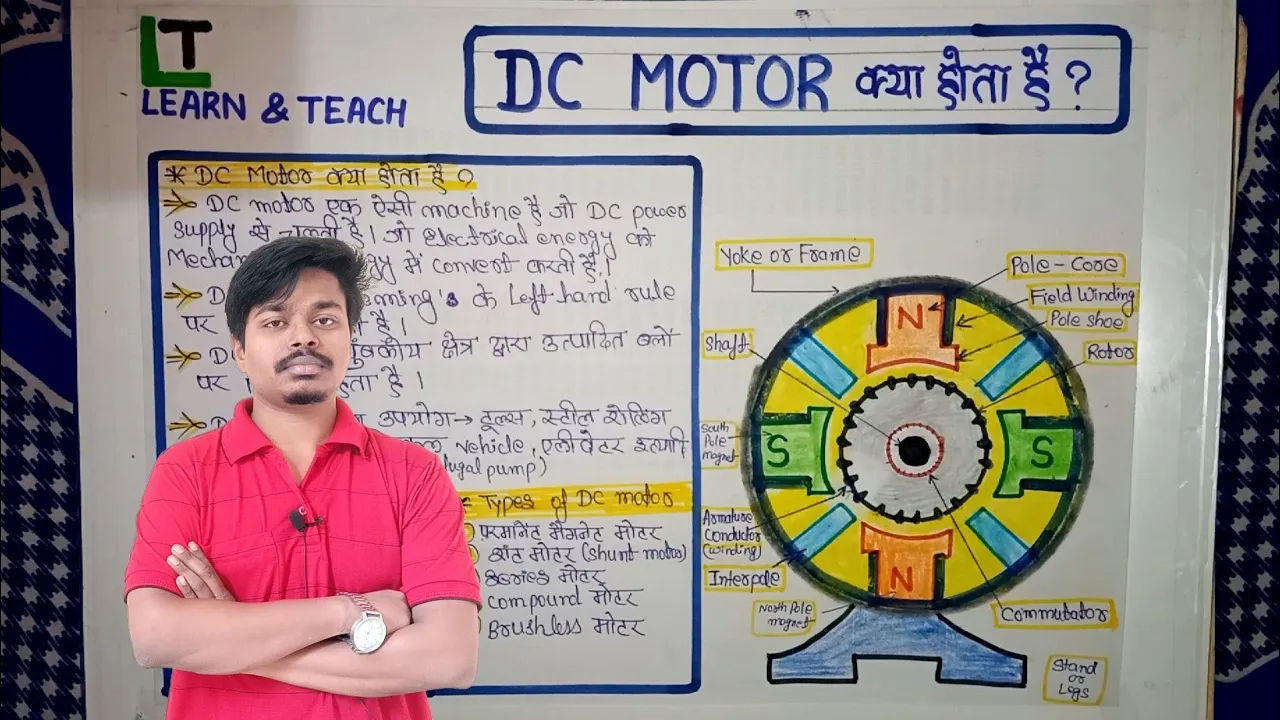
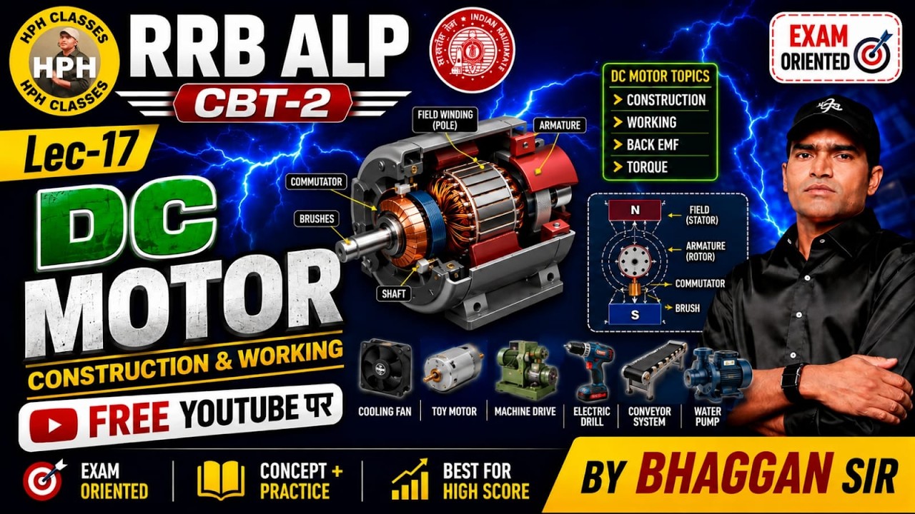
Added:Fundamentals of DC Motors: Understanding how standard direct current (DC) motors operate using electromagnetism and rotation.
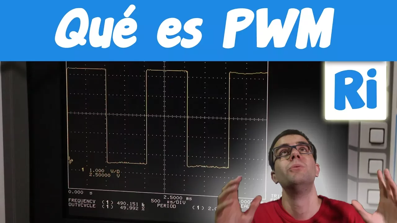
Introduction to Pulse Width Modulation (PWM): Knowing how duty cycles control power delivery and signal encoding to represent analog values digitally.
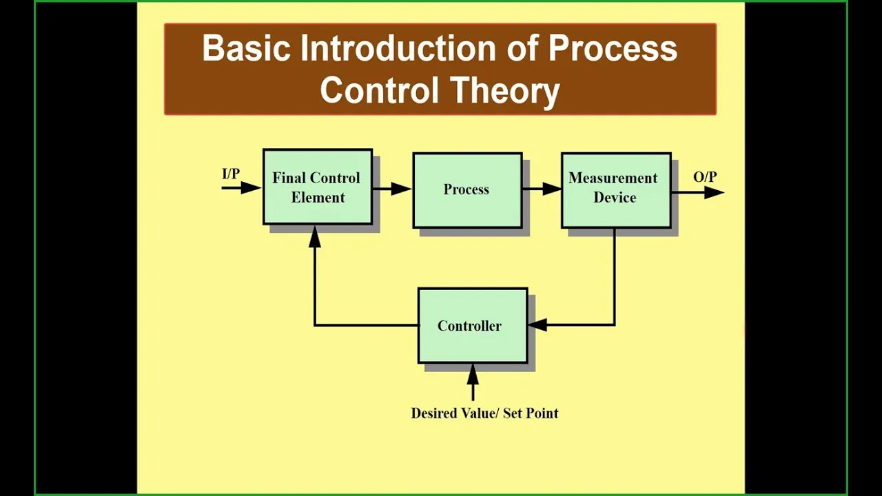
Basic Feedback and Closed-Loop Control: The conceptual difference between open-loop systems and systems that adjust based on sensor feedback.
Essential Circuit Theory: Familiarity with basic electrical concepts such as voltage, current, ground, and safe wiring practices.
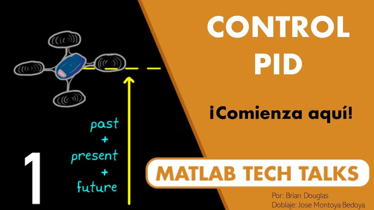
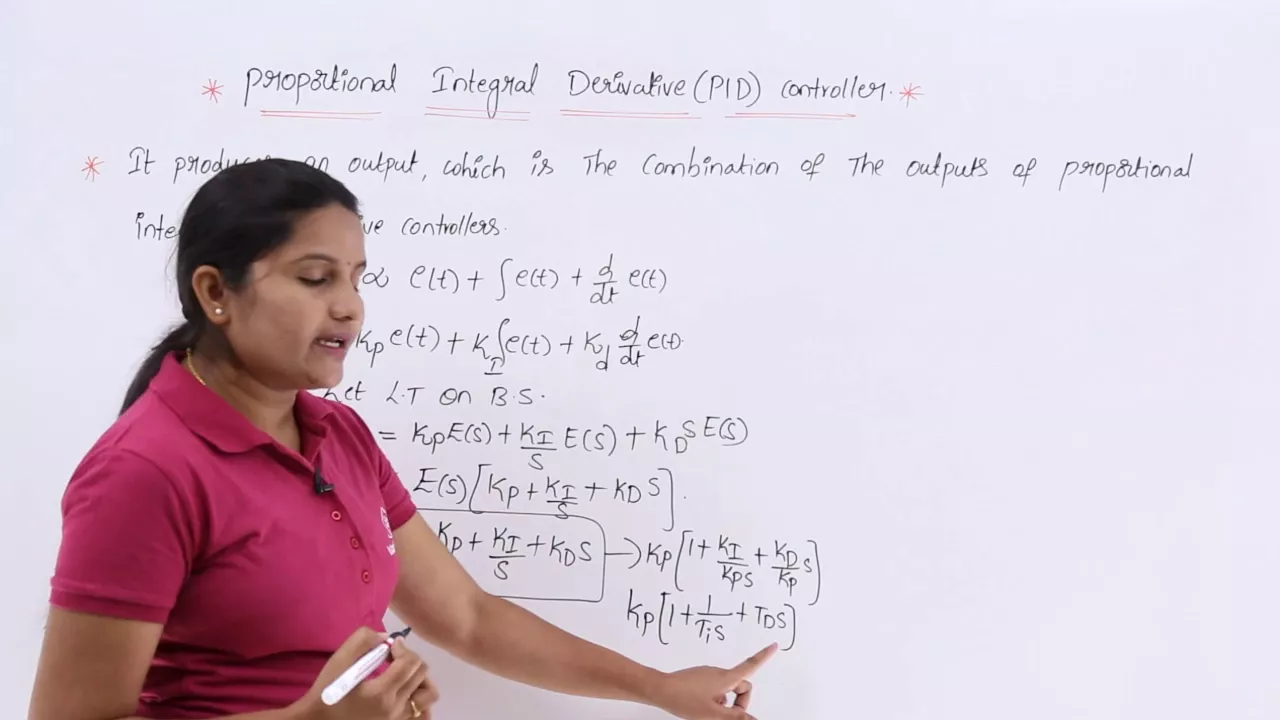
PID (Proportional-Integral-Derivative) Control: Learning how mathematically tuned feedback loops optimize motor precision, speed, and reduce overshoot.
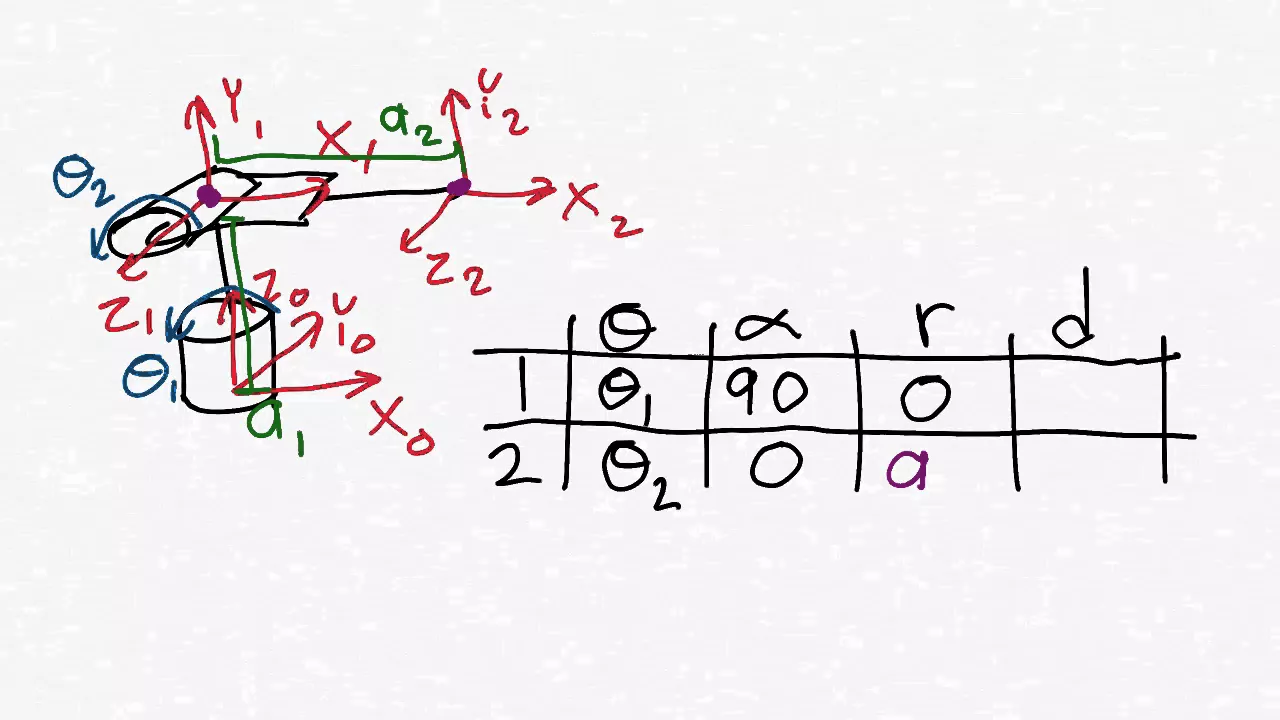
Robotic Kinematics: Applying multiple coordinated servos to control jointed mechanisms, such as robotic arms or legged walkers.
Industrial Servo Systems: Exploring high-torque AC/DC brushless servos, absolute encoders, and field-oriented control (FOC) used in automation.
Multi-Servo Communication Protocols: Programming microcontrollers to control dozens of servos simultaneously using I2C/SPI and dedicated servo driver chips (e.g., PCA9685).
977K views18.8Klikes5:54Original Release: 2016-10-23
when it comes to positioning tasks in a project a ster motor is usually a safe bets but there exist another popular motor driven positioning system called Servo which combines the motor with control Electronics in an easy to use package and in this video I will show you how such a server works and how you can easily use one in your project with and without a microcontroller let's get started [Music] the most common servos all look very similar like these three here they all have a Sawtooth shaft on top in order to attach different kind of accessories necessary for your project and three wires coming out of them Brown is ground red is VCC which usually requires a voltage between 4.8 to 7.2 volts and orange is the control signal which needs to be a pwm signal with a periodic time of 20 milliseconds AKA 50 Herz and a duty cycle of 1 to 2 milliseconds so 5 to 10% while an on time of 1 milliseconds represents Theus 90° position of the motor shafts 1.5 millisecs represent the 0° position and 2 milliseconds the plus 90° position so we can rotate the shaft a total of 180° but before applying an appropriate signal let's remove the four mounting screws of the servo in order to remove the top and bottom cover on the top we can see four different size gears that decrease the original RPM of the utilized DC motor from around 3,000 to around 50 to 100 RPM and thereby also increase the torque but that is not all underneath one gearu height the shaft of a potentiometer that is located inside the servo this potentiometer creates a voltage divider that outputs a variable voltage according to the position of the motor shaft and acts as a feedback for the utilized control IC the KC 5188 the IC constantly compares the poin armer voltage aka the current states to the intended position of the pwm signal aka the target States and then activates an integrated H bridge to let the motor rotate in either direction to achieve a difference of zero between the two signals and that is basically how a common server works of course the torque and speed along with other useful information are always mentioned in the data sheet and just in case you need something be for your project you can always upgrade your Servo this mg 996r Servo consists of metal gears with a bigger motor to increase the torque and a control IC with separate n Channel and P Channel mosfet ic's to form an AG bridge that can handle more current but let's get back to the control signal after connecting the servo to a separate power supply we can easily use the pin9 of an Arduino and a bit of code that includes the servo library to generate the required signal by using a pent cheter as an L loock inputs on pin a z i can vary the on time of the signal between 1 millisecond and 2 milliseconds but as you can clearly see here this input signal does not complete a 180° rotation of the servo instead we need something like 0.5 milliseconds to almost 2.5 milliseconds to utilize the complete 180° of rotation which the adrino library can handle as well but we don't necessarily need an uino to achieve this functionality a simple 555 timer I see with two resistors one diode two capacitors and a pent Chader in this constellation can create the pwm signal as well the on time varies between 0.5 to 2.45 milliseconds according to the position of the poeter and the off time is around 17.5 to 18.5 milliseconds this way the generated signal may not have a constant periodic time of 20 milliseconds but the servo does not really care about such small details and works just like we intended it but let's say you need a Servo that rotates 360° essentially like a normal motor does you could simply use a gear TC motor but your project would work best with the easy to mount Servo no problem here is an easy hack on how to do that simply remove the mechanical end stop which is usually attached to one gear remove the feedback potentiometer and replace it with two 10 kiloohm resistors to create a voltage divider that tells the control I see that the motor is always in its 0° position Now by applying an on time below 1.4 milliseconds the motor rotates clockwise and above 1.4 milliseconds anticlockwise in both cases with an adjustable RPM but sadly the feedback will never reach the target States and thus rotate forever and if you're too lazy for the hack there also exist pre-made servos with those modifications that even let you control the Zer degree state of the potentiomet and with that being said you already know quite a bit about servos I hope you like this video and learn something new as well don't forget to like share and subscribe stay creative and I will see you next time
Up Next
12:52
Design Digital Low-Pass Filters on Arduino
@curiores111
188.2K views•2021-06-20

30:32
Ultrasonic Transducers: Resonant Frequency Measurement and Horn Design
@imajeenyus42
229.9K views•2017-02-22
8:48
DIY Solar Tracker Experiment: Energy Yield Comparison
@greatscottlab
2.5M views•2018-07-01

33:39
How a Student's Question Saved a NYC Skyscraper from Collapse
@veritasium
22.8M views•2025-04-26
Related Study Plans & Knowledge Roadmaps
Structured learning paths in Engineering
engineering
Building Acoustic Levitators: Physics & Arduino
01The Physics of Sound and Standing Waves
02Piezoelectric Transducers and H-Bridge Drivers
03Arduino Programming: Generating 40 kHz Signals
+ 2 more learning modules
14h5 modules
Explore Roadmap
engineering
Building Peltier Cloud Chambers: Particle Tracks
01Cosmic Rays & Cloud Chamber Physics
02Thermoelectric Cooling (TEC) Fundamentals
03Custom Liquid-Cooling Loop Design
+ 2 more learning modules
18h5 modules
Explore Roadmap
engineering
Yagi-Uda Antennas: Modeling, Build & VNA Test
01Introduction to RF and Antenna Fundamentals
02Yagi-Uda Antenna Design Principles
03Antenna Modeling and Simulation in 4NEC2
+ 2 more learning modules
18h5 modules
Explore Roadmap
engineering
ECG Monitor Design: Op-Amps, Filters & Noise
01Electronics & Breadboard Basics
02Op-Amps and Instrumentation Amplifiers
03Bioelectricity and ECG Fundamentals
+ 2 more learning modules
18h5 modules
Explore Roadmap