
![🔵 SERVOMOTOR de 360 con ARDUINO [Giro Continuo] #023](https://i.ytimg.com/vi_webp/0oDvQIV4l9c/maxresdefault.webp)















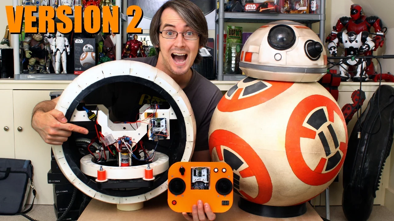











This video demonstrates the design and assembly of a BB-8 droid head control arm system, featuring a gimbal mechanism with two high-torque servos (HS 805 BB+) that control head movement through a flexible Ninjaflex linkage system. The design addresses the challenge of mounting the head control arm on the internal hub (banana) rather than the trousers to prevent interference with the flywheel stabilization system. The assembly includes bearings for smooth movement, a magnetic coupling for head attachment, and a servo horn system that converts rotational motion into the necessary head articulation. The design emphasizes modularity, allowing for future adjustments and improvements.
BB-8 Droid V3 Head Control Arm Mechanics Tutorial
Added:Fundamentals of Servomotors: Understanding how hobby servos operate, including torque limits, angular positioning, and pulse-width modulation (PWM) control.
Basic Kinematics and Linkages: Familiarity with mechanical linkages, degrees of freedom (DoF), and how rotational motor motion is converted into multi-axis mechanism movement.
Gimbal Mechanism Principles: Understanding the physics and geometry of gimbal joints used for rotational isolation and multi-axis orientation control.
Mechanical Assembly Techniques: Knowledge of standard hardware components such as ball-and-socket joints, bearings, and threaded fasteners used in small-scale robotics.
Inverse Kinematics for Robotics: Learning how to mathematically calculate the precise servo angles required to achieve a desired head posture or gaze direction.
Active Stabilization and IMU Integration: Combining inertial measurement units (gyros/accelerometers) with PID control loops to dynamically stabilize the head while the drive body is moving.
Magnetic Coupling Dynamics: Exploring how to manage magnetic attraction and friction when coupling the external head control arm to the internal drive system through a spherical shell.
Advanced Animatronics Design: Applying these multi-axis linkage principles to other robotic systems, such as bio-inspired neck mechanisms, robotic eyes, or camera pan-tilt platforms.
75.5K views1.8Klikes21:41Original Release: 2016-03-04
hello it's James makes robots not Cody UK this is part five of my bb-8 version three on my left we've got bb-8 version two which is a 10 part series you can see in my channel and now I'm hoping to improve on that mechanically and in terms of features we've version 3 which I've built up quite a bit here I'm quite a bit of work on today we're going to have a look at the head control arm and the head mounting but let's have a look at what we've done so far this is version 3 so I've got my 3d printed ball check out part one for me making that and sanding it all smooth inside we've got this kind of internal hub which I called the banana for obvious reasons and that's got lots of little guide wheels all the way around which is really printed with 3d printed ninjaflex tires on those who are mounted on bearings may help the banana run rounds in the way in the ball so obviously there's a drive wheel down there which is the red tire which has a motor a windscreen wiper motor and that drives along and obviously as it does so the internal drives and this rolls are long now for side to side stability which is what was missing from version 2 I've got the trousers because they're like a pair of trousers hanging on the washing line and those suspend a large amounts of mass in the form of this flywheel which can spin rounds to make the droid turn on the spot and that flywheel and all the mass also shifts so that has got another motor which moves with the flywheel on a toothed track and that makes the droid ship side-to-side for steering and stability so let's have a quick look at that so if I just connect that motor to a battery live got just here and run it you can see it leans over obviously it's really wobbly at the moment and eventually it's gonna be gyro stabilized so that make it lean over to stabilize or steer one way and also back the other way if I move some wires out from under it so that gives me quite a good angle of steer there for going around corners so dynamically moving the trousers side to side will help kill this sort of wobble that we get an inversion to that was quite a problem because it does that both when it's driving and when it's stationary so obviously we'll move that mass really quickly compensate today we're going to try and build the head control arm which of course will move the head around independently from both the banana and the trousers this isn't going to be the head dome this is what I use last time this is the other half of a globe which happens to be 280 million diameter so it's just the right size for this version I'm going to do something quite special and it's going to be much lighter but anyway we'll use this to demonstrate where the head goes for this discussion so my original plan was to mount the head control arm on the trousers so that as the flywheel moves one way the head always stays on top essentially because it remains always opposite so if I move were to move the flywheel over then the head would go this way and so I've just moved a flywheel to one side and we'd end up with the head over this side so my head would remain on the top or there abouts or obviously directly opposite the flywheel until we then move it independently to some degree and that made quite a lot of sense to me because that's exactly how it works front to back essentially what happens is the head is fixed to the banana and as the internal hub drives backwards and forwards to compensate and kill wobble and drive smoothly head of course always stays opposite and then it's then biased by its own mechanism to point forward when it's driving forward and move around or do whatever it wants to do so it's going to use the same logic to decide where the head should be mechanically and keep that directly opposite the main mass that keeps this thing weighted down however that's going to be a bit of an issue I think because the flywheel is going to have to move side-to-side the trousers here gonna have to move side-to-side quite quickly to stabilize this so to kill the short sharp sort of spikes in the motion it's gonna act a bit like a reaction where where it mousse quite quickly side to side and that's of course gonna have the effect of moving the head quite quickly the other way side to side which I don't really like the idea or off because I think it will throw the head off the magnetic coupling so having given it quite a lot of thoughts I've decided in fact what I'm going to do is mount on the head control arm on the banana and that's where the inertial measurement unit is also going to be then I can do what I like with this trousers and flywheel assemblies shifting it side-to-side to stabilize as quickly as I like and this is going to make more sense once I come on to do the electronics but for now I need to make a mounting assembly to get the head control arm mounted onto this banana the black piece at either end in a similar fashion subversion to my head control arm is of course going to have a magnetic coupling at the top which grips the head from the other side I'm going to make the head control I'm a lot lighter and a lot simpler for this I had fairly large 3d printed gears two servos and other motor with 3d printed gears and all sorts of things this one is going to be a lot simpler so all I'm going to do is build a gimbal around this middle which is why I've left this piece completely blank to make a stick that sticks up and then I'm going to push it around the stick is also gonna have a servo in the bottom the makes it turn so that doesn't have to turn too much force because again I'm gonna split my head base into two have a look at so I'm about part two or three of version to build I actually have a separate magnetic assembly that rotates inside the ball cast does all the caster wheels on the head so that I can turn the dome without turning all the wheels round so we have a servo that turns the arm and some surveys that pushing rounds so the basic plan is to have some of these servos which are fairly large these are high-tech HS 805 BB plus servos so rather large servos that do about 20 kilograms of torque I'm going to mount one of those each side so one will be here one will be on the other side and simply put that's all it's gonna be so I'm gonna happen some rather larger horns on these that push this stick around so when both surveys push hold the stick goes forward when they both pull back in pulls back and when one pulls forward and one pulls back should shift it sideways I'll ship you have to get quite a bit of travel there now I mentioned I was gonna mount these servos on the trousers so I was just going to have little brackets that put them here I want a bit to do that in the future if this plan doesn't work so the plan is to still mount them about here only I will have a bracket to hold them onto one end of the banana and there's still a bit of axle there as well to mount it on so they will sit about here and if the plan of mounting them on the bandana doesn't work then all I need to do is make an alternative brackets and mount them on the trousers and they should have exactly the same effect and the same placement hopefully so the first thing I need to do is try and fit these servos in here by working out in CAD and then we'll build the gimbal and the rotational stick with the magnetic coupling on top right we're back to the CAD for the whole assembly that I've got here I've changed the ball to a transparent material so I can see through it but nonetheless we can hide that and have a look right inside so obviously we get rid of these as well the purple parts there are screwed 3d diagrams I've drawn of the servos that I've just shown you there they are much larger than a normal survey so it's been quite a consideration to fit them in and they fit some sort of on this plate and the plate is mounted both to the banana which is sort of green here those are the black edges we can see in real life with the brackets it's also mounted in here to that spare bit of axle and you'll notice wipe done for accessibility is made sure that I can screw it on from the sides with these blue plates rather than from the top or bottom because it's going to be very hard to get my hand in there once this plate is in place so that should work pretty well I can actually test moving the trousers and the flywheel rounds this is the new version of one to 3d design which is free and it now has a smart rotate feature where I can select a face which will be the end of this axle I can select a solid and then if I can find it I can tilt it sideways so I think I've got about 20 degrees of motion there so I can see that my trousers don't run into anything and I can tilt that back the other way as well and we can test that out and check that everything's good so here's that assembly on its own I've built the top plate there in two parts I can print them both flat on the bed they're both six mil thick and then I can take out any warp by screwing those back to back the other bits and pieces will screw on and hopefully that should all fit in there fine right here it is so I've printed all the parts and assembled them I've sold them welded the two layers back to back so you can see the seam but you can also see that it's dead flat that's too screwed in there for now I could solve them weld it similarly these are so this piece goes the other side of the axle and we'll eventually screw on to grip it and the screw on to the banana so there it is fitted now it's all screwed in and screwed in there and it seems to fit fine so I can move the trousers because I've tested that and they move freely and don't get caught on it obviously they're off to one side there and these servos seem pretty strong at least from that point of view they're attached to the banana pretty well so now I need to implement the stick and the gimbal in the middle here which will actually hold the magnetic coupling at the top so that looks roughly like this we've got this red part of the bottom which goes around the main axle if I just hide this we can see that we've got some four meal holes that go all the way through to connect the two halves together and we've got space in each side for a 8 mil in a diameter bearing so that should be able to be tightened around that aluminium tube I've got to get the right tension so it can move sideways then of course the other piece will rotate the other way so that's got bolt holes that go in the ends and the servo fits in the middle that turns the head and again we've got bearings in the top and bottom of the top part so then of course that can move in all directions which gives me my three axis and I played all the parts out you can see around here for printing they're all printed in two halves so they're flat on the bed and I can stick them back to back to get rid of any wool here we are so those are the two halves they go around the main axle and this piece then hinges that way so I've got the bearings pushed in there already I need to put some eight mil studying through here and put a nut on each side and I've got my other bearing here and here so we're going to use a servo in the middle this is a fairly high torque servo but it is only a 180 so the head will only turn 180 degrees I could put a 360 in but for now that will do and I need to attach something to these screw holes to hold the survey tabs on the side and then a piece of 8 mil studing will go in the top and I need to make a coupling to attach that to the servo horn so it can rotate so let's get those bits and pieces made and then we should be to fit that in the last part will be attaching something to these screw holes which are the two couplings the other two servos will push to push this all around so here we go I call those extra bits printed I've got this thing attached to the top of the servo and I eventually will have a mill studing fitted in it's pretty tight so I need to screw it in then I've got this nuts and bolt that can tighten up the grip it's and that's how that's going to work and of course that's attached to the servo and the servos got these little brackets so that it can be fitted in here and another bracket at the other side to hold it and hopefully that hole aligns okay there so what I need to do is think we're stubbing in and put a couple of washers on so that we've got a bit of a spacer between the bearings so that's a big gray thing if it sadly doesn't get pushed against there there's no gap so that stops the magnets pulling against this motor we should be to pop that in here we go so I can now screw the studing straight into that hole and pop a couple of screws in there and a couple of screws in there and now this servo you should turn the studing and of course on the other end is where the magnetic head mount is located and this goes right in the middle of the Droid right so this is together I've put some bits of studing in here and I've slot in the end so I can screw them in and the nuts and some washers on the inside to get the spacing right so of course this now fits over here and gets screwed into those bearings they can turn that way and it can turn this way right here it is installed so all the C can move backwards and forwards and pivot side-to-side and it's got loads of motion so this is Ford's back not quite as far as that block is in the way where the servo is but that's more than enough motion really the servo is probably won't meet to push it to that extent and obviously we've got some restriction on the topic of the magnetic coupling which will hit these sides at some points but that should be more than enough with the ball in motion as well hopefully you can see I've just installed a servo horn on here so they came with a round ones which are made of a nylon and they're really tough what I've done is put this kind of camera shaped thing on there's a hole in the end there and this can rotate all the way around so the aim is to move the head stick by altering size of a triangle essentially so these two surveys will come out to the head stick and if I can change the su sides of the triangle then I can of course move e battlers and Fords and if I make one side very short and the other one side very long you should move this way if I do it the other way it will move that way but I do need some sort of flexible coupling to attach this onto the head stick because of course the shaft will have to move around as the head stick moves so let's see what that looks like I've printed a piece and this is printed on the lulzbot mini flexi strudel so it's made of ninjaflex and I can bend it so this is going to mount up on here and I've got a little shim that I made our rigid ABS which can screw and hold it to the two screw holes so that goes on there and now of course is the two mounting points so these can bend and they can twist as well a little bit which makes a sort of all-in-one universal joints really they're also quite rubbery to push so it's going to be a bit of flex which you lack it's erm a bit like a dampener if there's any short sharp shocks so I need to get some sticks and a couple of those with another flexible thing at the server end well I've made the arms and I've made them out of partly ninjaflex and partly out of rigid abs and I've just screwed that together and I put these extra holes in so they can bend really easily in one place if it's too bendy there is ninjaflex semi flex which isn't quite as bendy this is about ninety percent solid so it's pretty much solid ninjaflex obviously this goes onto the ninjaflex parts I printed before this goes onto the servo horn so it can bend like that so hopefully this will be good enough to see if the angles are right and these lengths are right but let's fit those and see how it looks hopefully you can just about see how fitted that linkage is in there and I've put them on from both sides so they're pretty firm as I so might upgrade them to semi flex they didn't actually need to bend that much but um I've got quite a good range of motion so if I pull go for servos back then my head goes completely back I push them forwards it's about the end it goes all the way forwards and obviously one for someone back will bring it over sideways and the other way brings it over there okay further so now let's take at that side and if I do a combination of them I can you know bring the head around in all sorts of motions so I'm pretty happy with that the only slight challenge is when it's completely back there is a bit of wobbling done because the leverage angles really sharp the only way to solve that would be to bring this these longer and bring them to the in front of this but when I actually move these and move them both forwards then it's pretty much there's a little bit of play but they're pretty much locked in a straight line so that seems to work out pretty well side to side motion is not too bad with the magnetic head coupling on this I think that's as far as it's gonna go anyways I think that's going to be fine so pretty happy with that we're not really going to know how it's actually gonna work to its in motion but on the whole I'm pretty happy the other thing I'd like to add is that the Droid is still quite heavy in the bottom so if I tip this over it's more than happy enough to bring itself upright again the other one just tipped over by itself sometimes so those really wobbly as I said before that will be gyro stabilized by moving the trousers and the flywheel sideways quickly and driving the motor back and forth but there is actually enough mass in the bottom they'll bring itself upright now I still have the magnetic head coupling and the head to build which I'm going to be doing next time that's all there is for this episode and next time I'm going to be coming back to build that magnetic head coupling that goes on top of the head control arm we built this time and also most of the head structure if you want a clue to how I'm going to make that really light have a look at the Star Wars Episode seven visual dictionary image of bb-8 you can find it if you google hard enough and I should give you a fairly good indication of how I'm going to save weight on the head alright so I have actually published the CAD for all of the parts up to this episode on github if you have a look at github comm /x robots you can see both versions too and in fact all three versions of bb-8 mi are six droid i'd suggest not following too hot on my heels in printing the parts because as I've said in this episode and the last one I may come back to revisit some parts so I don't want anyone to waste too much time before I've actually got the electronics working and we can see how this handles in real life so that's all for now don't forget subscribe for more updates on this project and other projects and also check out the social media links in the description of this video
Up Next

19:15
qPCR Essentials: DNA Quantitation Methods & Workflow
@FIUForensics
1.1K views•2012-10-02

12:54
Triumph of Orthodoxy Icon: Byzantine Art & History Explained
@BenCallan
2.1K views•2024-08-06

17:29
Active Omni-Wheel Design and Mechanics for Two-Axis Control
@jamesbruton
2.8M views•2022-02-01

1:42
Game of Thrones Opening Credits: A Cinematic Analysis
@gameofthrones
46.3M views•2011-04-18
Related Study Plans & Knowledge Roadmaps
Structured learning paths in General & Interdisciplinary Studies
general-studies
Elevator Engineering: History, Physics & Cities
01From Hoists to Safety Brakes: The Dawn of Vertical Lift
02Hydraulic vs. Traction: The Engineering Physics of Elevators
03Modern Speed, Safety, and Algorithms
+ 2 more learning modules
12h5 modules
Explore Roadmap
general-studies
Rubber: Material Science, History & Geopolitics
01Origins of Natural Rubber & Mesoamerican History
02The Chemistry of Natural Rubber & Vulcanization
03The Geopolitics of the Rubber Boom & Colonization
+ 2 more learning modules
12h5 modules
Explore Roadmap
general-studies
Containerization: Evolution, Logistics & Trade
01Ancient Trade & Bulk Cargo: Amphorae to Barrels
02The Industrial Revolution & Cardboard Packaging
03The Containerization Revolution: Malcom McLean
+ 2 more learning modules
12h5 modules
Explore Roadmap
general-studies
Textile Tech: Evolution, Labor & Global Impact
01Pre-Industrial Textiles: Handloom & Cottage Industry
02Mechanization: The Spinning Jenny to the Power Loom
03The Factory System & Global Labor Transformation
+ 2 more learning modules
10h5 modules
Explore Roadmap