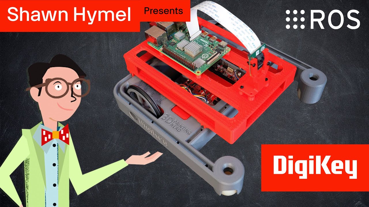
![[GHW Open Source] Getting started with ROS 2 for Open Source projects](https://i.ytimg.com/vi/8pZYK6qACH0/maxresdefault.jpg)


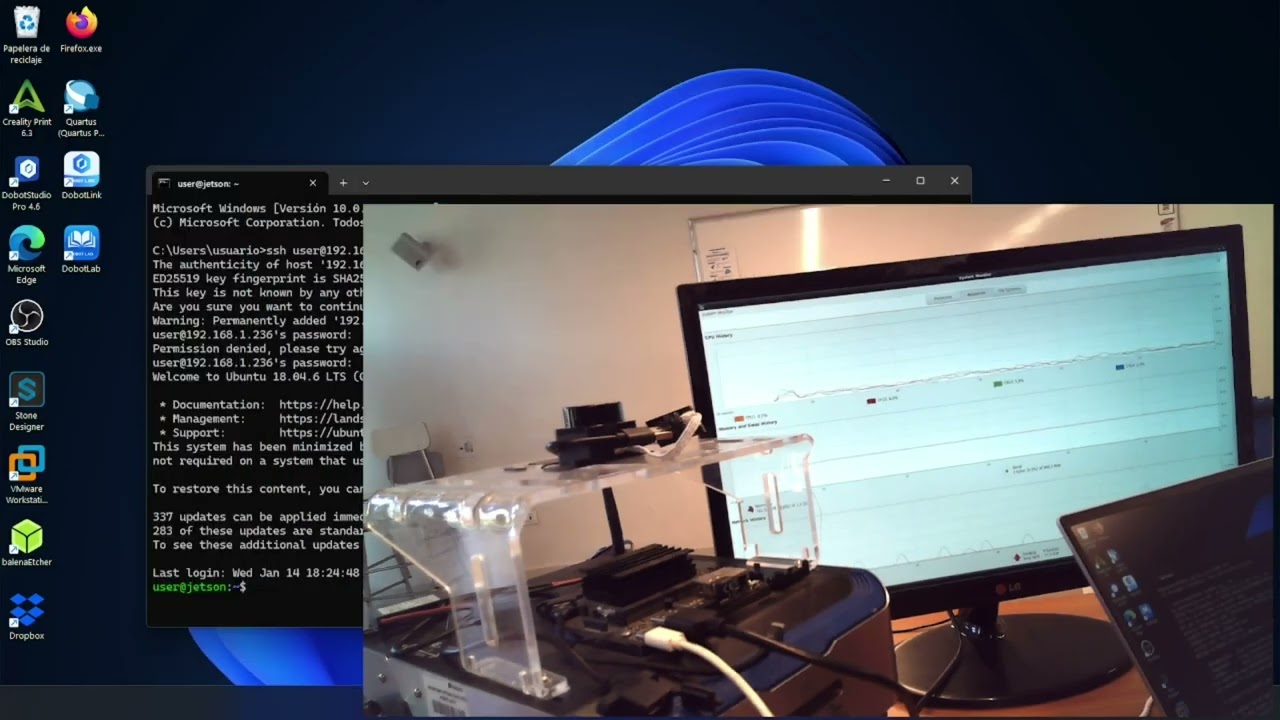

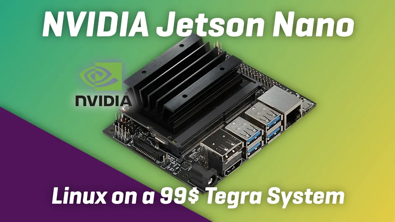












This video demonstrates how to set up ROS navigation on an autonomous robot using the Jetson Xavier NX as the compute platform, covering hardware integration (brushless motors with ODrive controllers and 8192 CPR encoders), software configuration (Arduino Teensy 4.1 for motor control and sensor interfacing), and the essential ROS components including TF transforms, odometry messages, and laser scanner integration to enable mapping and autonomous navigation capabilities.
Autonomous Robot Navigation with ROS Setup on Jetson Xavier NX
Added:Basic concepts of ROS (Robot Operating System), including nodes, topics, messages, and workspace setup.
Familiarity with the Linux terminal, Ubuntu operating system, and SSH connections on NVIDIA Jetson boards.
Foundational understanding of 2D LiDAR data structure (LaserScan) and robot coordinate frames (TF/Transform tree).
Introduction to mapping and localization theories, such as Gmapping/Cartographer (SLAM) and AMCL.
Implementing sensor fusion (e.g., Robot Localization) by combining LiDAR, IMU, and wheel odometry for robust state estimation.
Transitioning from ROS 1 to ROS 2 (Nav2 stack) to leverage advanced navigation features and better real-time performance.
Integrating depth cameras and Visual SLAM (VSLAM) to achieve 3D obstacle avoidance and semantic mapping.
Utilizing NVIDIA CUDA and TensorRT on Jetson Xavier NX for edge AI, such as real-time object detection and dynamic avoidance.
119.6K views3.5Klikes27:04Original Release: 2020-11-10
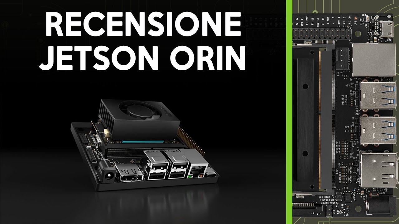
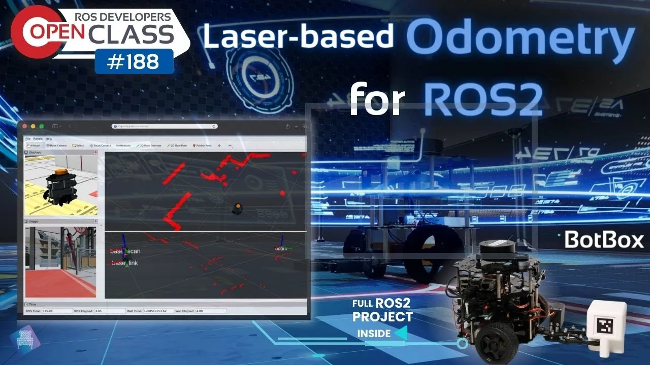
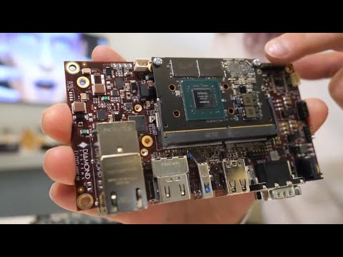
this is part two of the really useful robot check out part one to see how i made the main mechanical assembly and it's called the really useful robot because it's got this quite substantial base that can run around the floor without getting tripped over and it's got this utility stick made of aluminium v-slot extrusion they'll eventually have a body on that goes up and down and that's going to have an arm on that can come right down to reach the ground or it can go up to reach surfaces at human height so it can actually be of practical use in the home or office this is running a jetson xavier nx and that means we can run nvidia's the learning models to recognize household objects and it's also going to be running ros for mapping a navigation with a laser scanner that we're going to fit today and that lives just on the front so we'll look at that a bit later and mainly today we're going to try and get ros on this so that mapping and navigation works properly all i've done since last time is add the springs onto my suspension arm which is this flap that's got one of the casters on so that gives me some suspension and that's because it's got four wheels so we don't want to get grounded those springs are pretty tough and lots of the masses in the front anyway so basically it tends to fall forwards i've also added the control panel which was missing last time which is of course got the emergency stop on it various power switches a couple of volt meters and another button and we're going gonna wire all that stuff in today inside we've got the main drive which is two brushless motors with belt drives down to the wheels and each one of those has got an encoder on the back we've also got the two batteries in the front here which are going to power it and that's what i mean when i say it's quite front heavy in the middle here we've got an o drive 3.6 each of those motors has got encoders and those the 8192 cpr encoders as well as the o drive motors so we can accurately drive those motors and get the velocity estimate all done by the o drive in the back here we've got the jetson xavier nx which is going to be the main compute module i've also got a team c4 which is going to sit just in here and that's going to sit in between the xavier and the rest of the hardware like the o drive and any encoders and things we have for that arm and the body that's going to go up and down i've also made this additional little battery pocket which is 3d printed and that holds an 11.1 volt lipo and that's the powder xavier which will run on between 9 and 20 volts roughly it comes with a 19.5 volt power brick they'll definitely run on 12 volts the jetson nano does not though if you've got a jets and nano it needs five volts do not plug it into a 12 volt battery obviously the main drive for this is going to be higher it's going to be 24 volts so that's going to power the wheels and then we have a separate battery for all the logic so basically that's why i've got two power switches on my control panel and two volt meters before we get on with the wiring i just want to say thanks to some of the companies who've got on board and helped me build this project it's been quite inspiring i think to do an open source ros robot with some ai in it so thanks again to 3d fuel for providing the 3d printer filament for this whole project and also for the rest of this project when i've built the stuff that's up there and some of my other projects thanks to nvidia again for providing the xavier nx check out the nvidia jetson projects page that link is in the description to the video and thanks to cool components providing the teensy 4.1 in fact that's in there which we'll be looking at in a moment and lastly thanks to robo savvy who've provided the laser scanner for this project this is an rp lidar a2 that we'll be looking at later in the video robo savvy sell all sorts of robotics projects including the robotis turtlebot series dynamics or servos and lots of other robotics projects so check out robosavi.com right let's get on with some wiring right let's talk about power systems i mentioned i had two batteries one to power the xavier and we've still got the other one here which is to power the o drive that's 24 volts and that's 12 volts so the xavier is switched on and off with the power switch and that's absolutely fine because that's a 10 amp toggle that's more than enough power but the o drive is going to be configured for 20 amps on axis so i didn't want to use a 10 amp toggle to turn it on and off now we do have the emergency stop which is this one that's actually going to reset the o drive to cut the motors off as an emergency so we don't actually need to cut power when the motors are running but nonetheless i've used a relay which is very similar to this one which is a 40 amp 24 volt relay and that sat just down there you can just see it so the switch turns the relay on and that turns the o drive on so we've got 40 amps instead of just 10 amps and i was going to use a far bigger thing to cut power in an emergency like this which is apparently a 200 amp contact which is like a really big relay but that one draws half an amp just to energize the coil so i decided not to do that and use the smaller one that will only be a few milliamps hopefully so it doesn't drain the battery powering up the relay my o drive is of course wide to the brushless motors and it's also wide to the power via that relay it's also wide to the encoders so that's what those two wires are and basically we could go and plug this in with usb to the xavier which is sitting just here or we could link it to a serial port on the zapier and use it directly what i've actually done though is why the serial port off to a teensy 4.1 which is sat here and that's connected with usb round to the xavier as i mentioned we're going to be putting rods on this robot so we can make it do mapping and navigation with the rods navigation stack and all those nodes that are already built to read the laser and do all of the things we need we have got quite a bit of config ahead of us though now why if i put that team c in between the xavier nx where roz is going to run and the o drive and the answer to that is really that i'm quite comfortable programming arduino compatible micro controllers like the teensy i've used those in a lot of projects before in my previous ros robot we just used an arduino mega and that dealt with all the wheel encoder handling and controlling the motors that's plugged into a raspberry pi running roles as well as the laser scanner which is another usb device that's also the case for turtlebot which has an opencr board which is another arduino compatible microcontroller has a raspberry pi that runs rolls but then basically we use that ros serial library which allows us to publish messages ros messages and ros topics straight off a micro controller over serial to the main computing platform and so i want to really copy it and do it that way and i feel that that's quite a sensible approach because it makes it really modular and that means i've got some code that i can run on any robot even if it's a robot dog or another wheeled robot that has that kind of hardware microcontroller aspect that handles everything and deals with publishing the messages and then we can just run the raw serial node on the raspberry pi or the xavier or a jetson nano whatever we choose to do and that can handle the rest of the rolls communication to make a ros robot that uses the navigation stack to do mapping and navigation with a laser scanner we need a robot that can do several things so basically roz has a rods call that you run up somewhere it can be on this computer in here or it can be on a remote workstation and that rollscore allows lots of nodes to register with it and then they can talk to each other and those nodes will do various things and we publish various topics that any of those nodes could subscribe to and we have messages within those topics so first of all we need to be to drive the robot accurately so we need to be able to go and publish a command velocity topic either manually with a program that we can press keys to drive it or the navigation stack will of course command the robot to make it drive around and that command velocity topic contains the velocity we want the robot to drive at forwards and rotationally and if you're a halonic robot with omni-directional wheels also sideways and if it can fly up and down as it is we're only differential drives so we're only going to drive forward and rotate so first of all we need to receive that message and command the motors to go at the right speed now that's made easier in this case because the o drive already does its own encoder handling has its own controller so we can just say go and run the motors at a specific speed work out the belt reduction the wheel diameter work out how many meters a second is traveling and give it that demand and it will hopefully go and do it so that is quite easy for the navigation stack to work though we also need to send back some data about where the robot actually is so one of those is tf which is a transform and that tells it where the robot is with reference to its starting point so we have basically a starting point wherever we start when we switch the robot on and if you imagine the room is divided up in a grid with x and y coordinates and also the rotation of the robot we need those three bits of data published as a transform so we know where the robot is with reference to where it started its position and its pose we also need to send back an odometry message which contains that data and it also contains the velocity in a straight line or as much as it can be driving forwards and also its rotational velocity now that's made easier because we can read the encoder positions and the encoder velocities back from the o drive and that makes it much easier to do those calculations than having to control your own encoders and motor speeds like i did in the last robot i worked out all of my wheel encoders the belt reduction the circumference of the wheel and obviously the width between wheels as well as required to work out how much we turn when we run the wheels by a certain direction and all of those calculations are in a text document that i'll put up on github which finally tells us how many encoder counts we need to turn one radian a second and how many we need to go by each meter of travel in a linear direction i've then gone and written my arduino code and i've used the odrive library and also the ros library with various other things that we need to publish all of those messages so it's quite a bit of code i'm not going to go into too many details but i will put it up on github and i had to hack some of the arduino libraries to make it work as well and i'll put an explanation on github for that too as well as the hacked libraries so it finally ends up down the bottom we're publishing an odom message with all of these components and publishing the transform with all of these components my robot's powered up i've put some blue tape on the motor so you can see them turning and i've blocked this up on some wood so it doesn't run off the table and we can run the motors without anything else happening obviously i've got my terminal attached here with the keyboard and everything to the hdmi port eventually we'll ssh in to operate it remotely but for now i've run up the serial raw serial node on here we can see that it says it's published the messages that i put in the code so now we can go over to a ubuntu workstation that's over this way and we can go and operate the robot and see what the messages are that it sends back over on my workstation i've got roscor running here over the network the xavier nx has wi-fi on it so this is connected over the network we've also got the keyboard teleop program and here we've got the tf message so we can see what's happening here so as i start driving the robot around we should see the motors turning we'll find that x is getting bigger and y is staying still unless i start steering sideways and then we should start seeing that y gets bigger and if i steer the other way we should find it get smaller again or whichever way it is it's hard to know which way around the robot is facing at the moment we should also find if i turn sideways we get the angular position changing and that's measured in radians if we go and look at the odom message we can see we've got that position data still but now we've got some velocities so we've got the angular and linear velocity so if i drive forward here and then i increase the speed we should see that the velocity increases and that's coming back from the wheel encoders this is our angular velocity so if i turn sideways we should see that we get a velocity there kind of similar to what we're putting in probably it'll be low when it's on load when the robot's on the ground but before we try actually driving it it's time for a quick ad from another brand that supports my channel and that is pcbway pcbway provide both pcb manufacture and pcb assembly under the same roof so you can get them to solder the components onto your pcb as well as make the board itself as well as standard fiberglass pcbs pcb way can manufacture aluminium pcbs flexible pcbs and rigid flex pcbs which are part rigid and part flexible prices start at just five dollars for ten pcbs or thirty dollars for 10 pcbs of assembly but new customers can get five dollars credit so you can get your first 10 pcbs for free pcbway also offer advanced services such as pcb design x-ray inspection electronic probe inspection impedance control and various certification capabilities including rohs and ul certification find out more now at pcbway.com and i've put that link in the description to this video right let's give that robot a go on the floor there's probably some calibration to do on this but for now we're going to drive it around and look in rvs and we're going to inspect that tf message to see where the robot moves and see if it moves the right distance and turns the right distance where it thinks it is basically to match up what's going on in rods with what's going on with the physical robot so we've got odom and bass link on top of each other at the moment and if you remember the transform is the distance between the two essentially so if i go and drive this forward we should see the robot baselink driving away from odom and if we turn we should find it turns around let's just zoom out a bit here so let's just turn on the spot and we should see it driving all the way around doing a 180 and heading back to where it was roughly and i can drive this pretty well we can increase and decrease the speed and it appears to be doing roughly the right thing in rods so these squares are one meter and we should find if i drive for the meter then we get roughly um one meter in arvis and that's basically a good way to calibrate the robot we may need to do some more work on it we could also combine other sensors like an imu to make sure that we are actually moving when we think we are and there isn't wheel slip but that's another whole thing to build in and we need to build that into the coherence part of the odom message now it's time to put the laser in and get all that data into arvis and check that the laser scan lines up or at least the laser scan stays still as the robot moves around in the environment if it doesn't it means there's something wrong with a calibration of our wheel encoders so thanks again to robo sappy this is an rp lidar a2 this is slightly nicer looking than the a1 i used in the previous robot at least it doesn't have a drive belt hanging out and stuff and it's slightly better spec so hopefully this should give us quite reliable results my laser is going to sit in here and i left an access hole for the wire to go out of course and it's got this little board on which has got a usb micro connector on so we need to route this cable through the robot and then plug the cable in from here into the xavier so that's mounted plugged in and i've got the ros node that comes with it running so that's now spinning and you'll notice what i've done here is mounted it just in front of the stick that holds up the top of the robe but when i've built it and this is within the minimum range of the laser so i'm hoping this will just return invalid data so we've got about 150 millimeters till it'll start working properly so if you just ignore this stick if that's not the case then we can use the laser filter ros node which allows us to take out certain angles so the robot doesn't see itself or certain minimum distances but i'm pretty confident that's within the minimum distance of the laser so it should just ignore it but to make the laser work we need to tell ros where the laser is mounted in this case because it's on the robot or we could have sensors that are fixed in the environment so we're going to publish another transform that tells us where the laser is mounted with reference to the base link of the robot so if you remember we have that odom which is stationary and there's a transform that tells us where the robot is moving around in space and then we need to transform from the base link to where the laser is so in this case it's about 20 centimeters off the ground and slightly further forward than the center of rotation of the robot there's multiple ways we could do this we could do this with the arduino code to publish a static transform we could do it on the command line just by publishing a static transform but in this case we can have other stuff on the robot like the piece that goes up and down a robot arm maybe other sensors so what we're going to do is use a urdf file and we're going to use the robot state publisher and the joint state publisher nodes to look in that urdf file and then publish that transform to the rest of ros so you can see where the laser is this is the terminal session on our ubuntu workstation looking at the actual xavier nx1 so i'm looking at the file system on the actual robot here so in our catkin workspace source folder we've got a folder called are you our description and in there is a urdf file i've made this as minimal as possible again so normally we would have more things in here we could have pointers to 3d models so we get a simulation rendered in arvis but for now i've just gone for the minimal amount of links and things that we need so we've got a base link and we've got a laser link and then we've got a joint which is fixed and that associates the two together and basically what i've done here is said that the laser is positioned forwards 163 millimeters and it's positioned up 300 millimeters i've also switched it round by pi radians which is 180 degrees and that's because there's something about this rp lidar node and it's the same with the a1 the switches the data of the laser round 180 degrees so i've basically switched it around so it faces the right way and the laser data matches the robot we've also got a launch file in another folder and that is basically a script like a startup script that's going to launch all the nodes we need so that has various parameters in it including pointing to the urdf file mainly it launches the joint state publisher and the robot state publisher nodes which are also installed in the source folder it also launches the raw serial python node and the serial node so we can communicate with the arduino and it also launches the rp lidar node so that the laser works to compile all the nodes we run a catkin make which i've done before so it doesn't take very long and that actually compiles the node so they can be launched into roles and to launch that launch file we can just go and do a ros launch with the package name and the launch file so tf is basically the glue that binds all of our ros environment together and tells us where things are so we've got odonto base link base link to laser and we'll have another transform from base link to the other joints and things on the robot when we've built them so for now we've got everything published off the xavier nx as well so we've got that arduino connected all the teensy publishing tf and odom we've got our laser that's connected to the xavier as well publishing the laser data and all the transforms are published off the xavier as well so pretty much the robot's one contained thing there's no other nodes currently running on a workstation we can look at those messages anywhere on the network look at those topics put them in rvs and we should now be to drive the robot around as we did before and see tf moving as the bass link moves but we should also now be to see the laser scan the laser scan should stay still because it's scanning the room and the robot should move within it and if you don't get that then something else bad has happened now i did have a problem to start with with the laser being switched around 180 degrees it's very confusing because the laser scan moves in the opposite direction to the laser and that's why it's switched back around so that the laser data matches the robot now i'm running my remote workstation under vmware and there are some display issues with alves i've colored my laser red but you can see it's still white which is why it's quite hard to see but we can see that the map the laser scan at least is staying still as the robots moving around if we increase the decay time we can see there is some slight drift when i rotate and i've tuned it the best i can with some scaling factors which i've put into the arduino code but i think that's going to be okay we do get some drift but as the next rotation comes round it seems to correct it so on the whole the map stays pretty still if i drive forward and backwards we should be to see those walls there's a little bit of blur but they're not too bad we could still tune that but it's going to vary depending on the floor surface if there's drag on carpet and so on if we zoom right in and look at our transform we can see the laser is facing 180 degrees the other way around because that's the only way it works and also that there's a slight offset between the base link and laser and that's represented in 3d within rvs all of the stuff up to now is fundamental and incredibly important for getting your robot to map and navigate properly if you haven't got tf in place you haven't got your odom message you haven't got your links between odom and bass link and baselink and laser and when you drive around if the laser doesn't stay still then basically there's no point in going any further but the next thing is to build a map of the environment and to build the map we're going to use the g mapping node which is available from github you just put that into your catkin workspace source folder and to a catkin mate to compile it in there are quite a lot of parameters which i totally ignores and i basically just use the stock settings there's one command to run it of rolls run to run the g mapping package and the slam g mapping node and point the scan at your scan topic which in my case is just called scan it's not called base scan that publishes a topic called map that we can just add into arvis and then the map appears and as we drive around with the keyboard teleop program it should draw a map of the environment and obviously this is very dependent on your odometry data and your laser data and those things matching otherwise the walls will come out blurred and lots of features appear where they aren't really there but we can see that's drawing the map okay whoops crashed a bit there but that's okay as long as the wheels um don't get stuck so the odometry data is correct and we can drive around the whole of the environment and we should be to build the map after that there's a command to save the map which saves an image file which is basically an occupancy grid with black dots where there's something it can't drive through and white in the rest of the space so you could edit that as well if you wanted to the map server will allow you to save that with the map saver command that stuff's pretty easy what's not easy is a navigation stack we now need to implement to actually make the robot navigate now it's probably worth a 20 minute video on its own so i'm not going to go into lots and lots of detail but basically what i've done is taken the knox robot project config files which i used in my last ros robot and also the turtlebot config files and i've mashed the two together and i've read all the documentation found out as much as i can what all the parameters do and try to tune it for this robot so they're probably with someone with more experience you could do a better job but it seems to work okay for now the core concepts are basically a cost map so looking at the features of the map and seeing what the cost or the sort of risk is of traversing that piece of the map so how close objects are and so on there's some obvious parameters for the physical size of the robot the inflation radius of obstacles and there's also a bunch of parameters around sort of the velocity and so on and this cost map allows you to have a multiplier that means as you get closer things get exponentially more risky or higher cost so there's quite a lot of config in there now i'm going to publish all the config files everything from the arduino code and the cad which is already published all the way through to all of my config files i'm sure some people will have comments on the way i've done it but for now we're just going to do a demo so now i can position a 2d nav goal on the map and it should plan a path and the robot should drive there which it seems to do pretty well now you'll see my map's got lots of colorful colors on it now we've got the original map which is essentially black and white then we've got two more layers on the map we've got one which is light blue which is an inflation radius and you can see that around the walls and that's the distance it won't go to them so it will leave some clearance the robot also knows how big it is so it can avoid obstacles on top of that we've got the pink layer and that is marking and clearing so as the robot's going around it's rescanning the room to look for other obstacles like a person stepping in the way and we'll do a demo in a moment of that so that it can actually add to the map and then clear things when they disappear so that appears to be working pretty well you can see orient itself at the end of driving so it points in the same direction as the arrow and mostly it seems to be working pretty reliably so let's put a new obstacle in the way we're going to put this attractive piece of furniture here and you should see immediately gets added to the map now if we plan a course to drive past it instead of hugging the kitchen unit there it should give that a nice piece of clearance and we can see that clearance again highlighted in blue and we can see the circle which is the radius of the robot so it knows how to avoid it without getting stuck too badly so i'm going to move that now to make a thinner corrie door to see how well it navigates between that so let's turn the robot around and we're going to face it the other way so it's got to turn round now you can see the path gets planned one way and then it changes the robot gets a bit confused spins around a couple of times but then it finds its course again and i'm not sure if that's because of drift in the laser or on a dormitory issue or just that it planned the path the other side then changed its mind but one way with the other that seems to work okay let's go back the other way and we should find that that works perfectly hopefully so avoids those obstacles it avoids the inflation radius and drives around and ends up where it should so needless to say i'm pretty happy of how that works it seems to go through doorways okay without getting too confused and all of those cost maps and the associated config seem to work okay provided we don't do anything too crazy to confuse it so let's just drive back the other way and turn the robot around so we should see that it drives backwards so quite a bit despite that blind spot and then it should switch around in the other direction where there's space to do so of course taking into account any marking and clearing and the map itself and it should drive round and turn to orient to face the arrow so needless to say i'm very happy of how well that works i'm really happy that i've worked my way through pretty much from scratch all the way through from the wheel encoders all the way up and through the navigation stack and everything seems to be working quite well so of course this sort of config and raws and navigation is going to work its way into other projects in my channel eventually including the robot dogs hopefully so we can actually do mapping and navigation on legs not sure how easy the odometry is going to be for that one and of course we've got that xavier nx in there so we can do deep learning models and we can put more sensors on and do vision recognition and all of those things so check out my channel for more examples of that already so thanks again to all the brands that supported this build and there's some more coming for the rest of this in the future hopefully and thanks also to patrons and youtube channel members and if you'd like to support me through either of those platforms the link is in the description to this video so don't forget to like and subscribe for more serious robotics and also some not so serious robotics alright that's all for now [Music] you
Up Next

0:42
Stereo Camera Mapping with RTAB-Map ROS Tutorial
@alexandergrau887
599 views•2024-08-09

12:54
Triumph of Orthodoxy Icon: Byzantine Art & History Explained
@BenCallan
2.1K views•2024-08-06

17:29
Active Omni-Wheel Design and Mechanics for Two-Axis Control
@jamesbruton
2.8M views•2022-02-01

1:42
Game of Thrones Opening Credits: A Cinematic Analysis
@gameofthrones
46.3M views•2011-04-18
Related Study Plans & Knowledge Roadmaps
Structured learning paths in General & Interdisciplinary Studies
general-studies
Elevator Engineering: History, Physics & Cities
01From Hoists to Safety Brakes: The Dawn of Vertical Lift
02Hydraulic vs. Traction: The Engineering Physics of Elevators
03Modern Speed, Safety, and Algorithms
+ 2 more learning modules
12h5 modules
Explore Roadmap
general-studies
Rubber: Material Science, History & Geopolitics
01Origins of Natural Rubber & Mesoamerican History
02The Chemistry of Natural Rubber & Vulcanization
03The Geopolitics of the Rubber Boom & Colonization
+ 2 more learning modules
12h5 modules
Explore Roadmap
general-studies
Containerization: Evolution, Logistics & Trade
01Ancient Trade & Bulk Cargo: Amphorae to Barrels
02The Industrial Revolution & Cardboard Packaging
03The Containerization Revolution: Malcom McLean
+ 2 more learning modules
12h5 modules
Explore Roadmap
general-studies
Textile Tech: Evolution, Labor & Global Impact
01Pre-Industrial Textiles: Handloom & Cottage Industry
02Mechanization: The Spinning Jenny to the Power Loom
03The Factory System & Global Labor Transformation
+ 2 more learning modules
10h5 modules
Explore Roadmap