This video demonstrates how to calibrate the Vref (reference voltage) on an A4988 stepper driver for a DIY CNC machine, which is essential for achieving accurate motor control and preventing missed steps during operation.
A4988 Stepper Driver Vref Calibration Guide for DIY CNC
Added:Deep Dive
Understanding of Ohm's Law and basic electrical concepts such as voltage, current, and resistance.

Lei de Ohm Formulas Curso de Eletrônica Básica Grátis #4
72.2K
Ohm's Law is named after German physicist Georg Simon Ohm, who conducted experiments to study electrical relationships. The law involves three fundamental electrical quantities: Voltage (Tensão Elétrica), Current (Corrente Elétrica), and Resistance (Resistência). Voltage represents the force that drives electrons between two points, while Current is the actual flow of electrons. These quantities are interdependent - without voltage (force), there is no current (flow), and vice versa. Ohm's Law establishes that changing resistance affects both voltage and current, and vice versa, allowing calculation of any one quantity when the other two are known.
Click to watch →

Ohms Law Explained - The basics circuit theory
2.3M
Ohm's Law states that voltage (V), current (I), and resistance (R) in an electrical circuit are related by the formula V = IR, where voltage equals current multiplied by resistance; this relationship can be easily remembered using Ohm's Triangle, which allows you to derive any formula by covering the letter you want to solve for (e.g., covering V gives V = IR, covering I gives I = V/R, and covering R gives R = V/I). Current is directly proportional to voltage (doubling voltage doubles current) and inversely proportional to resistance (doubling resistance halves current), making it essential for analyzing and designing electrical circuits.
Click to watch →
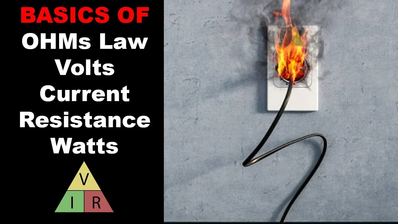
Basics of Ohm's Law, Volts, Amps, Ohms, and Watts Explained
70.1K
Ohm's Law (V = IR) is a fundamental principle in electricity that relates voltage (V), current (I), and resistance (R); voltage is the driving force that pushes electricity through a circuit, current measures how much electricity flows through a point, and resistance opposes the flow of electricity. Using the water analogy, voltage is like water pressure, current is like water volume, and resistance is like pipe restrictions. To use Ohm's Law, cover the unknown value in the formula and perform the corresponding mathematical operation: multiply to find voltage (V = IR), divide to find resistance (R = V/I), or divide to find current (I = V/R). Power (measured in watts) is calculated as P = VI, representing the rate of energy transfer.
Click to watch →

BASIC ELECTRICAL & ELECTRONICS | BEE | S-2 | FIRST YEAR ENGINEERING | SEM-1 | DC CIRCUITS |OHM'S LAW
402.5K
Ohm's Law states that the electric current flowing through a conductor is directly proportional to the potential difference (voltage) applied across its ends, provided the temperature remains constant; mathematically expressed as V = IR, where V is voltage, I is current, and R is resistance. This fundamental law explains how resistors control current flow in electrical circuits by providing opposition to current, similar to how a dam controls water flow. The law enables calculation of any one parameter when the other two are known, making it essential for analyzing and designing electrical circuits.
Click to watch →
Ohm's Law explained
1.8M
Ohm's Law describes how electricity flows through circuits. Voltage (V, measured in volts) is the electrical pressure that drives current, analogous to water pressure in pipes. Current (I, measured in amps) is the actual flow of electrons through a circuit. Resistance (R, measured in ohms) opposes current flow, similar to how narrow pipes restrict water flow. The Ohm's Law Triangle provides a visual tool to calculate any one value when the other two are known, making circuit calculations accessible without complex algebra.
Click to watch →
Deep Dive
Fundamental working principles of bipolar stepper motors, including phases, steps, and holding torque.
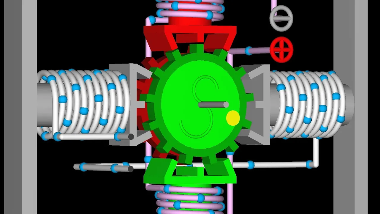
Stepper Motor Working Principles: Bipolar, Unipolar & More
156.6K
Bipolar stepper motors divide rotation into discrete steps using electromagnetic principles. The motor consists of a permanent magnet rotor interacting with electromagnet stators organized into phases. The left-hand rule determines magnetic polarity: wrap fingers in electron flow direction, thumb points to north pole. Torque is generated when stator fields attract rotor poles, causing rotation. The motor operates by sequentially energizing phases while reversing polarity, completing one full rotation in four steps with 90-degree steps for two-pole rotors or 30-degree steps for six-pole rotors. Counterclockwise rotation is achieved by traversing the operation table from right to left. Half-stepping doubles angular resolution by enabling both phases simultaneously before disabling the first phase, creating intermediate stable positions. Two-phase on excitation maintains both phases enabled throughout operation, providing higher torque but doubled current flow.
Click to watch →

Stepper Drivers: Simplified!
16.7K
Bipolar stepper motors contain two sets of windings (Phase A and Phase B) around a central rotor. When voltage is applied across these windings, current flows and creates magnetic fields that generate torque on the rotor. Current direction determines magnetic field polarity, enabling bidirectional rotation. The rotor continuously aligns with the net magnetic field produced by both phases. A 1.8-degree stepper motor completes one full mechanical revolution in 200 full steps (360° ÷ 1.8°/step), with four full steps constituting one complete electrical cycle. This means one mechanical revolution contains 50 electrical cycles. By sequentially activating phases with complementary currents, the magnetic field vector rotates smoothly, driving the rotor without zero-torque dead zones between steps. This fundamental operation enables precise positioning in applications like 3D printing.
Click to watch →
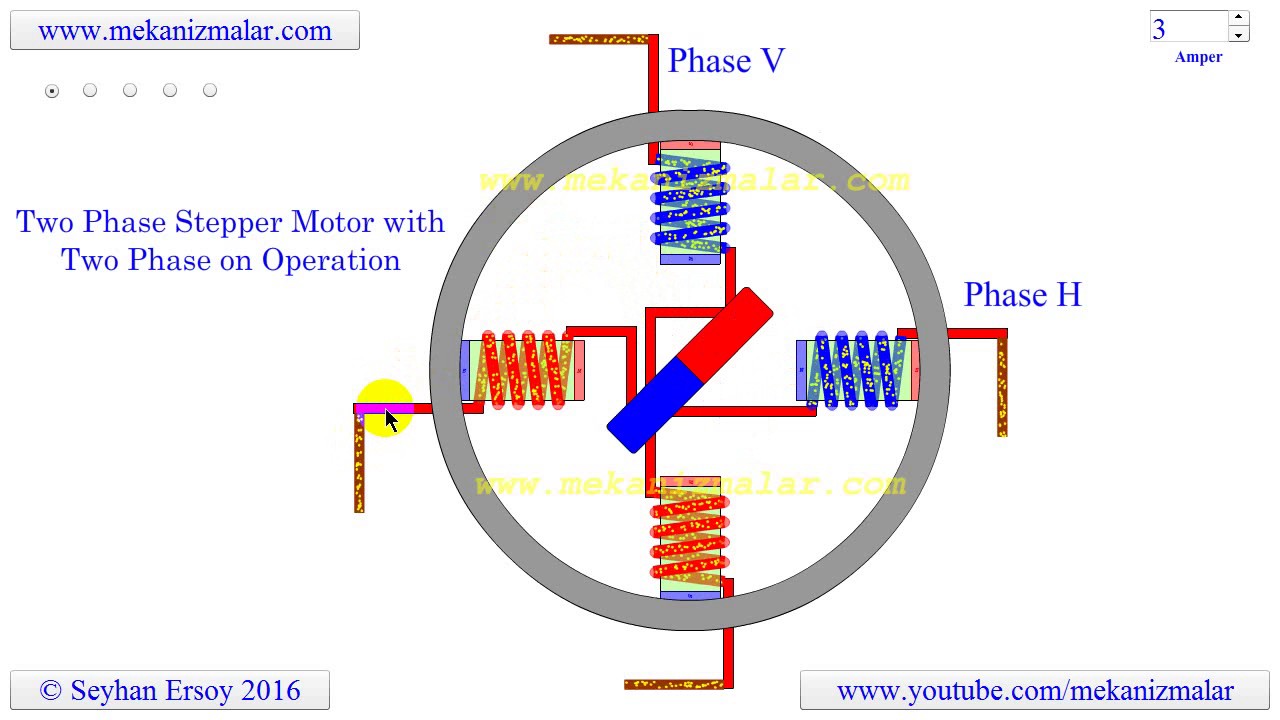
two phase stepper motor with two phase on operation
34K
A two-phase bipolar stepper motor operates with two bipolar coil windings (vertical V-phase and horizontal H-phase) where current flows through both coils simultaneously at any instant, with alternating polarity changes between phases; this configuration uses twice the power of a one-phase on motor but produces 41.4% more torque, and the rotor rotates 90° clockwise with each polarity change following a step sequence where V-phase polarity changes first, then H-phase polarity changes, repeating cyclically to achieve precise rotational control.
Click to watch →

Stepper Motor control using L298N Motor driver and Arduino.
19.1K
Bipolar stepper motors require four-phase control where each phase receives alternating current to produce rotation. The L298N controls these phases through IN1-IN4 pins. To identify phase groupings from unmarked wires, connect an LED between any two wires and turn the shaft—if the LED blinks, those wires belong to the same phase. Direction control depends on pulse sequence: clockwise uses IN1, IN2, IN3, IN4 in a specific order, while counterclockwise reverses this sequence. Each complete four-step cycle advances the motor one full step, requiring 200 steps for one full revolution.
Click to watch →

Как работает ШАГОВЫЙ ЭЛЕКТРОДВИГАТЕЛЬ? Шагаем, полушагаем, микрошагаем.
283.3K
Bipolar stepper motors convert electrical pulses into precise mechanical rotations through electromagnetic principles. They consist of a stator with multiple magnetic cores and a rotor with permanent magnets. The basic operation involves sequential energization of windings to create rotating magnetic fields that pull the rotor into specific positions. Key properties include holding torque (maintaining position when stationary) and step angle (typically 1.8° per step for 200 steps per revolution). Resolution enhancement techniques include half-stepping (doubling step count) and microstepping (dividing steps into hundreds of increments using unequal power distribution). Modern control uses PWM modulation to precisely regulate power, though audible noise can occur at certain frequencies.
Click to watch →
Deep Dive
The role of a stepper motor driver (specifically the A4988) in controlling current flow to motor coils.
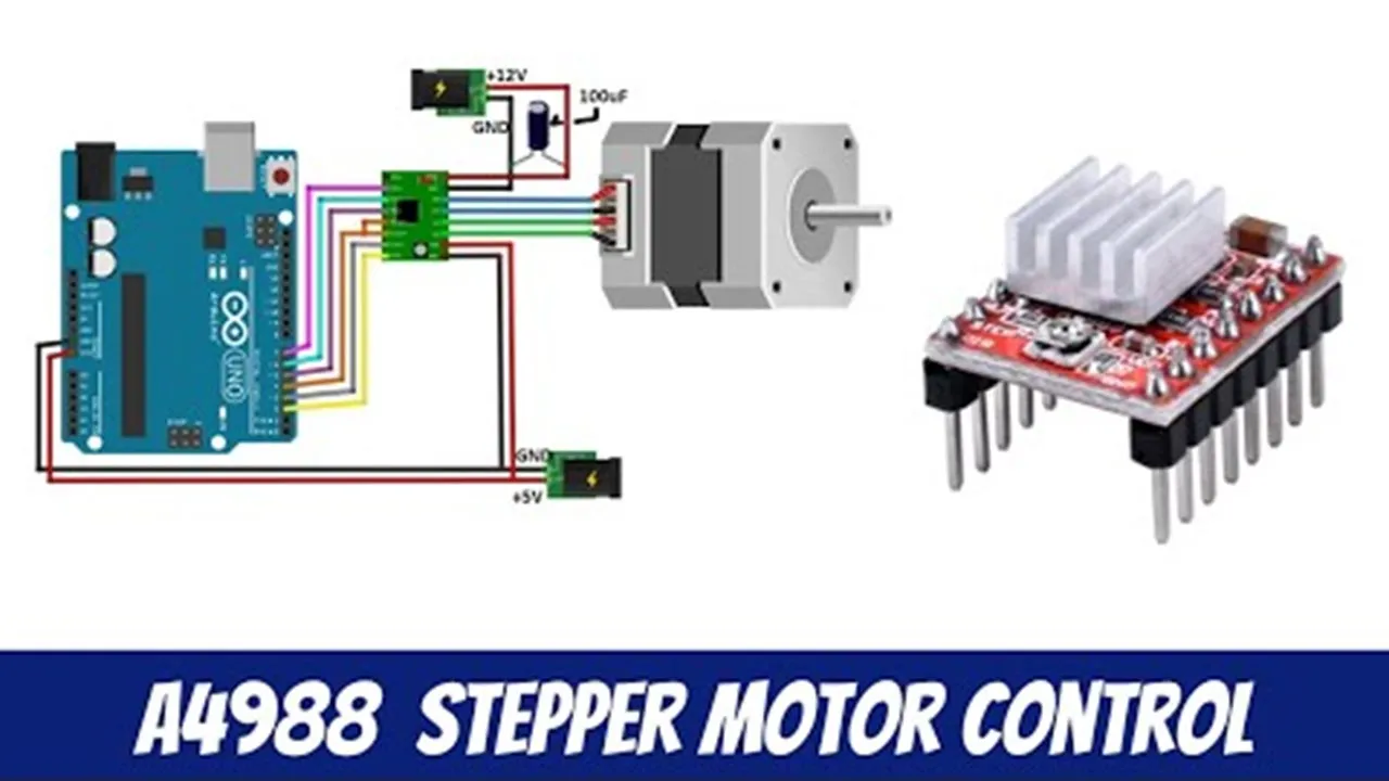
A4988 Stepper Motor Controller - Arduino & NodeMCU
165.1K
The A4988 is a bipolar stepper motor driver that controls motor operation through multiple configurable pins. Key components include: Enable pin for disabling the driver, MS1-MS3 pins for selecting microstepping modes (full, half, quarter, eighth, sixteenth steps), Reset/Sleep pins for power management, Step pin for triggering individual motor steps, and Dir pin for controlling rotation direction. The driver accepts motor voltage input (8-35V) and requires separate 3-5.5V logic power. The onboard potentiometer controls current limit through Vref reference voltage, calculated as motor rated current divided by 2.5 ohms. The driver can handle up to 1A per phase without cooling, increasing to 2A with proper heatsinking. Proper configuration ensures safe motor operation while maximizing performance.
Click to watch →
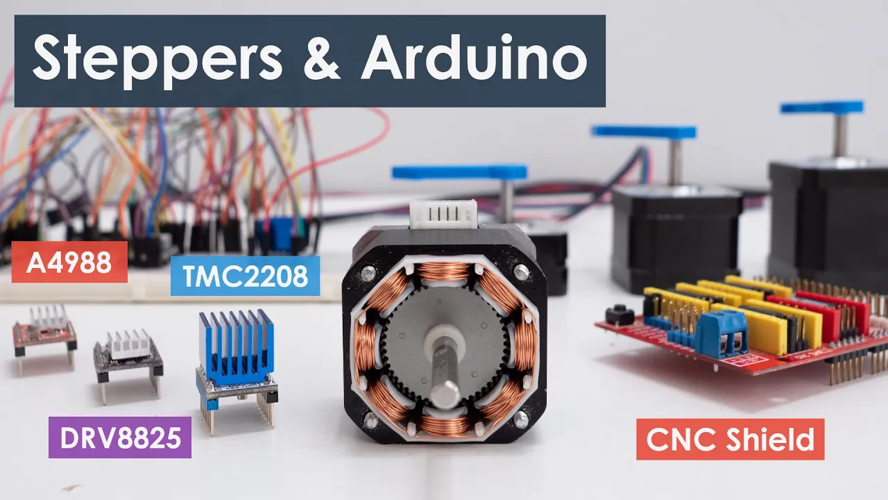
Controlling Stepper Motors with Arduino: A Guide
1.6M
The A4988 is the most popular driver for NEMA 17 motors, featuring a maximum current rating of 2A per coil (peak) with current limiting via a trimmer potentiometer. Key connections include motor power (8-36V), logic power (3-5V), motor outputs (A1-A2-B1-B2), step/direction pins, and control pins (sleep, reset, enable). Motor phase identification can be done by rotating the shaft - connecting wires from the same phase increases resistance. Microstepping increases resolution beyond basic steps: quarter-step provides 800 microsteps, full-step provides 200 steps, and the A4988 supports up to 16-microstep mode (3200 steps/rev or 0.1125°/step). The MS1-MS3 pins select stepping mode, defaulting to full-step when disconnected.
Click to watch →

How To Control a Stepper Motor with A4988 Driver and Arduino
970.7K
The A4988 is a microstepping driver for bipolar stepper motors featuring a built-in translator for simplified two-pin control. It offers five resolution modes: Full-step, half-step, quarter-step, eighth-step, and sixteenth-step. Key specifications include 3-5.5V logic voltage, 2A maximum phase current with cooling, and protective features like thermal shutdown and crossover current protection. The pinout includes VDD/GND for logic power, motor coil connections (1A/1B, 2A/2B), separate VMOT/GND for motor power (8-35V with 47μF decoupling), STEP/DIRECTION pins for movement control, SLEEP for power saving, RESET for home position setting, and MS1/MS2/MS3 for resolution selection with internal pull-downs defaulting to Full-step mode.
Click to watch →

🚩STEPPER MOTORS DRIVER A4988 current setup
1.4K
Stepper motor drivers like the A4988 differ from conventional H-bridge drivers (L298) by providing automatic current stabilization and generating control signals for motor windings. While H-bridges function as current/voltage amplifiers, stepper drivers handle complex logic and generate PWM signals with current feedback. Current stabilization is essential for high-speed, low-resistance motors in 3D printers and CNC machines, improving dynamic characteristics, limiting coil overheating, and expanding supply voltage range. Stabilization uses PWM controlled by a PID controller, with current set manually via a tuning resistor. The A4988 uses measuring resistors (RSC) to measure current through voltage drop, and voltage dividers (R5, R9) to create reference voltages for comparison. For a 1.7A motor with 0.1Ω resistors, the maximum VREF is 1.36V, and the recommended operating voltage is 0.95V (70% of maximum).
Click to watch →

How To Make Stepper Motor Speed Controller using A4988 Stepper Motor Driver | Arduino Stepper Motor
21.7K
A stepper motor speed controller using the A4988 driver controls motor speed by adjusting the delay between step pulses, where shorter delays (10 microseconds) produce faster rotation and longer delays (5000 microseconds) produce slower rotation; the A4988 driver manages motor current through its RSENSE pins and provides direction control via the DIR pin, while the ENABLE pin locks or frees the motor for safe operation.
Click to watch →
Deep Dive
Basic proficiency in using a digital multimeter (DMM) to measure DC voltage safely.

Lerne, wie man ein Multimeter benutzt!
199.7K
Digital multimeters feature digital displays, precision, ease of use, and multiple functions including voltage, current, and resistance measurement. They come in manual and auto-range variants, with auto-range being more user-friendly but pricier. DC voltage flows unidirectionally like river water, found in batteries and electronics. To measure DC voltage, connect red to positive and black to negative terminals. For auto-range meters, simply select DC voltage. For manual range, choose the next highest value (e.g., 2V for a 1.5V battery). If voltage is unknown, start with the highest setting. Always ensure components are powered for accurate readings, as voltage measures potential difference between two points.
Click to watch →

Apprenez comment utiliser un multimètre!
621.4K
Digital multimeters offer two main types: manual range (user selects scale) and automatic range (meter selects scale). Both provide digital displays for accurate readings. DC voltage (symbol: straight line) flows in one direction, found in batteries and electronics. To measure DC voltage: connect red to positive, black to negative. Auto-ranging meters display instantly; manual meters require selecting next higher scale than expected. If uncertain, start at highest setting and work down. Voltage represents potential difference between two points—measuring same point yields no reading.
Click to watch →

Basic Electrical Quantities (Full Lecture)
22.6K
A digital multimeter (DMM) combines three meters—ohmmeter, voltmeter, and ammeter—into one versatile instrument. Safe and accurate DMM use requires following a four-step checklist: (1) Select the correct function (resistance, voltage, or current); (2) Insert test leads properly (red in red, black in black); (3) Choose appropriate range manually or use auto-ranging; (4) Place the meter correctly for the measurement type. All meters have maximum safe measurement ranges indicated on the device—exceeding these limits damages equipment and risks personal injury. Some measurements require personal protective equipment. Each meter type requires specific placement: ohmmeters need disconnected elements, voltmeters connect across points, and ammeters must be in series with the circuit.
Click to watch →
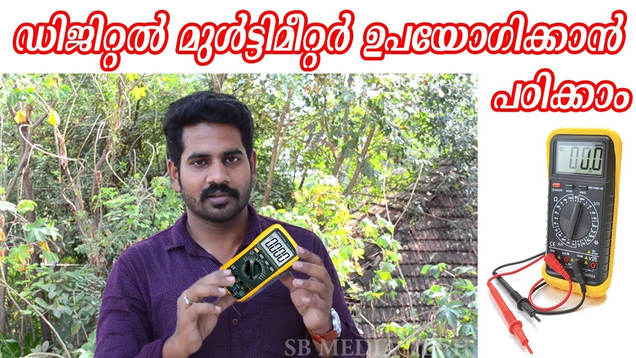
ഡിജിറ്റൽ മൾട്ടിമീറ്റർ ഉപയോഗിക്കാൻ പഠിക്കാം | How to use Digital multimeter malayalam
86.2K
A digital multimeter is an essential electronic testing device that measures electrical properties such as voltage, current, and resistance. To measure DC voltage, connect the multimeter probes to the power source with the positive probe to the positive terminal and the negative probe to the negative terminal. A fully charged 9-volt battery typically reads around 9.6-9.7 volts, while a depleted battery will show a lower reading. The multimeter's digital display provides precise numerical readings, making it easier to interpret compared to analog multimeters with needle displays.
Click to watch →

Multimetro digital
1.2M
Digital multimeters are versatile electronic measurement instruments that can measure DC voltage, AC voltage, resistance, DC current, AC current, and in some models, temperature, frequency, and transistor beta gain. To measure DC voltage, connect the black probe to the common/ground terminal and the red probe to the test point, selecting the appropriate voltage scale (e.g., 20V for a 9V battery). For unknown voltage levels, start with the highest scale and reduce it for accurate readings. Logical high levels should read approximately 5V with ±0.8V tolerance, while logical low levels should read 0V with ±0.1V tolerance.
Click to watch →
Prerequisite Knowledge
- Concept 01Understanding of Ohm's Law and basic electrical concepts such as voltage, current, and resistance.
- Concept 02Fundamental working principles of bipolar stepper motors, including phases, steps, and holding torque.
- Concept 03The role of a stepper motor driver (specifically the A4988) in controlling current flow to motor coils.
- Concept 04Basic proficiency in using a digital multimeter (DMM) to measure DC voltage safely.
Subsequent Learning
- Step 01Configuring microstepping resolutions (e.g., 1/16 step) on the A4988 using MS1, MS2, and MS3 pins.
- Step 02Implementing thermal management strategies, such as heatsinks and cooling fans, to prevent driver overheating.
- Step 03Exploring more advanced, silent stepper drivers like the TMC2208/TMC2209 and their software-defined current tuning.
- Step 04Configuring CNC firmware (such as GRBL or Marlin) with appropriate steps-per-millimeter and acceleration profiles.
Performance
Performance
2:01Playing Section
- 1
Musical segment with audience interaction.
- 2
Engaging live performance atmosphere.
- 3
Highlighting key musical moments.
Digital Current Control and Closed-Loop Systems: Moving Beyond Manual Vref Calibration
While calibrating the Vref on manual stepper drivers like the A4988 is a traditional method in DIY CNC building, modern motion control has largely shifted toward software-controlled drivers (such as Trinamic TMC series) and closed-loop stepper systems. Critics of manual Vref calibration point out that using a physical screwdriver and multimeter on a live board is highly prone to human error, often resulting in accidental short circuits that destroy the driver. Furthermore, A4988 drivers lack advanced thermal management and produce significant high-frequency noise. In contrast, modern TMC drivers allow users to configure current digitally via firmware (using UART or SPI), offering silent operation and automatic current scaling. Additionally, closed-loop stepper motors dynamically adjust current based on real-time feedback, rendering static Vref calibration obsolete. Advocating for manual A4988 tuning is increasingly viewed as promoting an outdated, risky, and inefficient practice when safer, software-defined alternatives are readily available.
Deep Dive
Configuring microstepping resolutions (e.g., 1/16 step) on the A4988 using MS1, MS2, and MS3 pins.
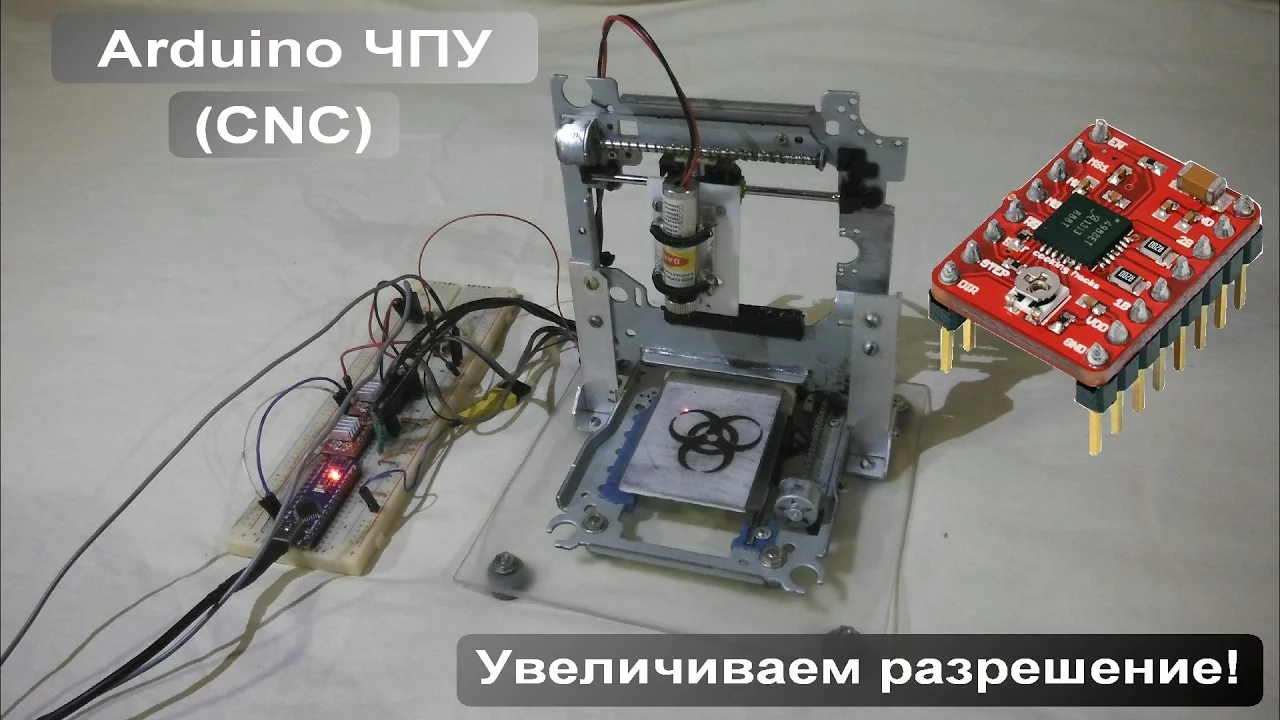
Лазерный ЧПУ гравер / Увеличиваем разрешение "микрошаг"
137.4K
Microstepping is a software technique that divides motor step angles into smaller increments (2, 4, 8, 16 times), enabling finer control and higher resolution. The A4988 driver supports microstepping up to x16, reducing step angles by 16 times. Configuration uses MS1, MS2, MS3 pins: all grounded for full step mode, all connected to positive for x16 microstepping. The driver provides adjustable current limiting (1A without heatsink, 2A with), enabling higher voltage operation for faster step response. Protection features include overheat, short circuit, and overload protection.
Click to watch →
Controlling Stepper Motors with Arduino: A Guide
1.6M
The A4988 is the most popular driver for NEMA 17 motors, featuring a maximum current rating of 2A per coil (peak) with current limiting via a trimmer potentiometer. Key connections include motor power (8-36V), logic power (3-5V), motor outputs (A1-A2-B1-B2), step/direction pins, and control pins (sleep, reset, enable). Motor phase identification can be done by rotating the shaft - connecting wires from the same phase increases resistance. Microstepping increases resolution beyond basic steps: quarter-step provides 800 microsteps, full-step provides 200 steps, and the A4988 supports up to 16-microstep mode (3200 steps/rev or 0.1125°/step). The MS1-MS3 pins select stepping mode, defaulting to full-step when disconnected.
Click to watch →
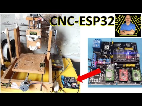
✅ Maquina CNC de Control Numérico con ESP32, Cómo diseñamos el PCB
60.6K
The A4988 stepper motor driver supports multiple microstepping modes through its MS1, MS2, and MS3 configuration pins. These pins determine whether the motor operates in full step, half step, quarter step, eighth step, or sixteenth step mode. The configuration is achieved by connecting these pins to either VCC (positive) or GND (ground). For example, connecting all three pins to VCC enables 1/16 microstepping, while different combinations produce other stepping resolutions. This allows designers to optimize motor performance for their specific CNC application requirements.
Click to watch →
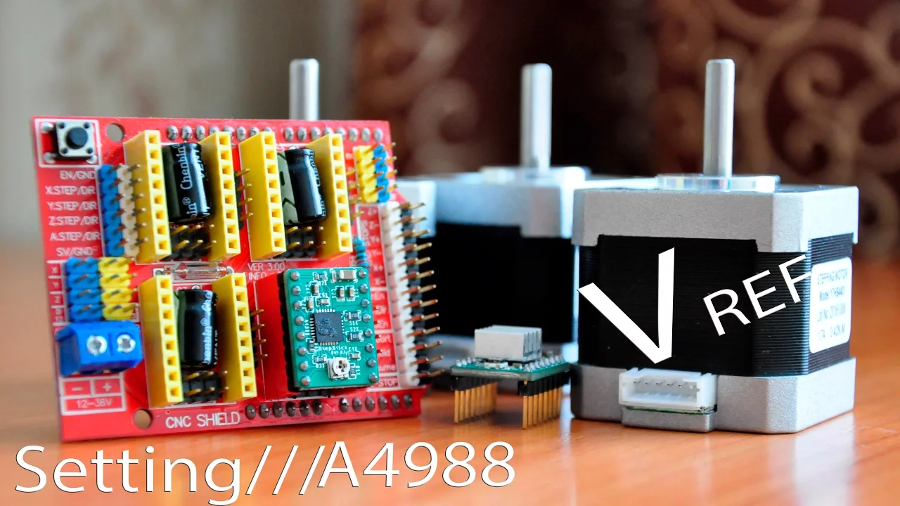
Настройка драйверов шаговых двигателей A4988 – Деление шага - ЧПУ станок (Часть 6)
219.9K
Proper current setting for A4988 stepper motor drivers is essential for optimal performance, reducing noise, preventing missed steps, and minimizing heating. The driver supports microstepping through jumper switches (MS1, MS2, MS3) that control step division ratios (1:1, 1:2, 1:4, 1:8, 1:16), where deeper division requires higher step frequency signals. Current limiting is adjusted via a potentiometer, with the formula: Limit Voltage = (Target Current × 0.7 × 1000) / 1000, accounting for the 70% current limit on both windings. The A4988 can handle up to 2A maximum, but currents above 1A require additional cooling.
Click to watch →
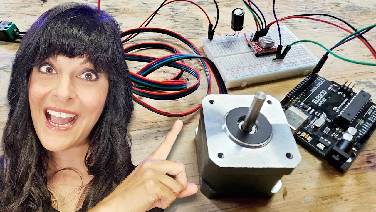
Control a NEMA 17 Stepper Motor with A4988 Driver and Arduino - Full Guide
134.3K
Microstepping divides each full step into smaller increments for smoother rotation. The A4988 supports quarter-step, eighth-step, and sixteenth-step modes through combinations of MS1, MS2, and MS3 pins. Default mode is full step with no connections. Quarter-step requires MS1=LOW, MS2=HIGH, MS3=LOW. Each microstep mode produces approximately half the torque of the previous mode but provides smoother motion. The example uses quarter-step with delayMicroseconds(2000) to demonstrate very slow, smooth rotation where each step moves only a quarter of a full step distance.
Click to watch →
Deep Dive
Implementing thermal management strategies, such as heatsinks and cooling fans, to prevent driver overheating.
Datasheet İncelemek Bu Kadar KOLAY! | A4988 Kullanmayın! / JLCPCB
31K
This segment demonstrates thermal management strategies with heatsinks and thermal vias. The presenter explains how thermal vias reduce junction-to-bottom resistance to ~1°C/W. With heatsinks on both top and bottom, the total thermal resistance becomes ~9.32°C/W (parallel paths). The calculation shows maximum power dissipation of 8.58W with Tj_max = 120°C and Ta = 40°C. The segment emphasizes that thermal management design directly impacts maximum power and motor current capabilities.
Click to watch →

CompTIA A+ Full Course for Beginners - Module 2 - Installing System Devices
136.1K
Heatsinks are metal components (typically aluminum) attached to CPUs to dissipate heat. They work by absorbing heat from the CPU and transferring it to the surrounding air. The heatsink features fins or veins that increase surface area for better airflow. A fan mounted on top of the heatsink blows air across these fins to cool the CPU effectively. This cooling principle mirrors automotive radiators. When installing a heatsink on a CPU, thermal compound (also called heat paste or thermal paste) must be applied between the CPU and heatsink. This viscous substance fills microscopic gaps between the CPU surface and heatsink base, dramatically improving heat transfer efficiency. Without proper thermal compound application, the CPU could overheat and sustain damage.
Click to watch →
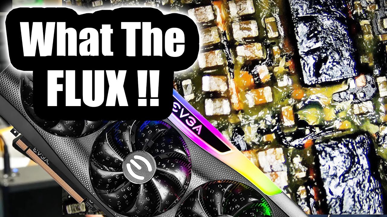
EVGA 3090 GPU Repair - Referred by Louis Rossmann The Villain
54.6K
GPUs require proper thermal management through heatsinks and fans to prevent overheating. During testing, six beeps following startup typically indicate overheating protection has been triggered. The video shows that reassembling the heatsink and ensuring proper airflow resolved the overheating issue, demonstrating that thermal management is critical for GPU functionality.
Click to watch →
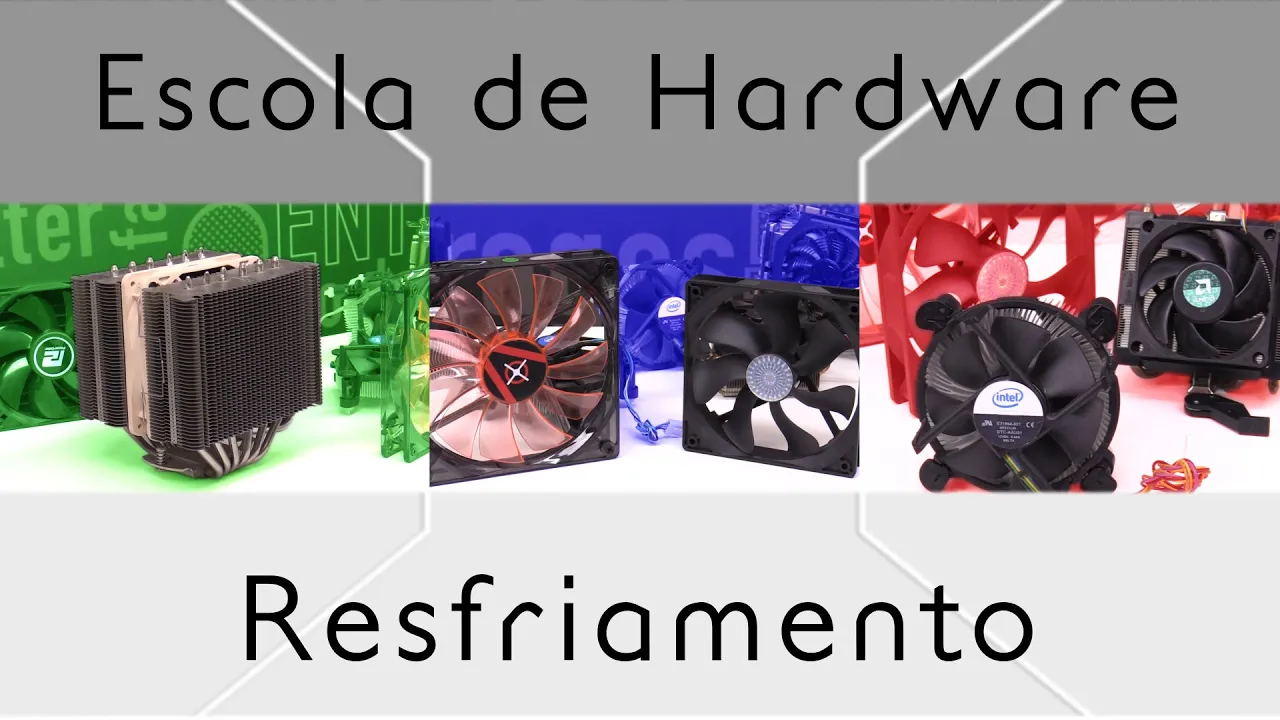
Resfriamento - Escola de Hardware - Episódio 6
304.2K
Computer cooling systems prevent component overheating through fans (ventiladores) that move air, heatsinks (dissipadores de calor) that transfer heat from components to air, and CPU coolers that directly attach to processors. Proper airflow direction is critical—fans should all push or pull air in the same direction to avoid creating a greenhouse effect. RPM (rotations per minute) indicates fan speed and noise level. Thermal paste facilitates heat transfer between CPU and cooler. Liquid cooling uses a water block, tubing, and radiator with fans for superior heat dissipation. Overheating can cause performance loss, system shutdowns, or permanent component damage.
Click to watch →

Who spends money like this? - Intel $5,000 Extreme Tech Upgrade
6M
CPU cooling involves multiple strategies: air cooling with heatsinks and fans, and liquid cooling with water blocks and radiators. The video demonstrates upgrading from AMD 5900X to Intel 13900K with DDR5 memory, representing a platform upgrade approach. Key concepts include CPU overheating warnings at 90°C, contact frames improving thermal contact by several degrees, and LGA socket installation requiring careful handling to avoid voiding warranties. Radiator fan design evolved from gap-filled frames to optimized pressure fans without gaps, improving airflow efficiency through radiators.
Click to watch →
Deep Dive
Exploring more advanced, silent stepper drivers like the TMC2208/TMC2209 and their software-defined current tuning.
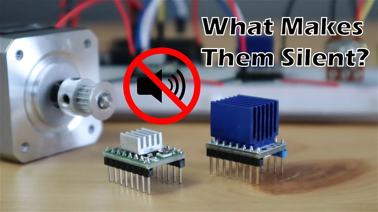
What Makes TMC2208 Stepper Motor Drivers Silent?
329.6K
The TMC2208 stepper motor driver achieves near-silent operation by generating a highly accurate sinusoidal current waveform (256 microsteps) compared to the square wave output of traditional drivers like the A4988, which produces more vibration and noise; however, this advanced control requires significantly more processing power from the microcontroller and may reduce torque at high speeds.
Click to watch →

Cambia los drivers A4988 por unos silenciosos TMC2208/TMC2209 en una impresora 3D
19.6K
This segment details the practical process of measuring and calculating driver current settings. The maximum current formula I_max = V_ref / (8 × R_s) is applied to determine each driver's current setting. For Pololu A4988 drivers, R_s = 0.05 ohms, while most Chinese drivers use R_s = 0.1 ohms. V_ref is measured using a multimeter by placing the positive probe on the adjustment screw and the negative probe on the GND pin. For the A4988 driver, the positive probe touches the adjustment screw head while the negative probe connects to the GND pin. This measurement allows calculation of the current each driver is set to deliver. The process is demonstrated on an Anycubic Mega printer, where the driver voltages are measured and recorded for later use in calculating TMC2209 settings.
Click to watch →
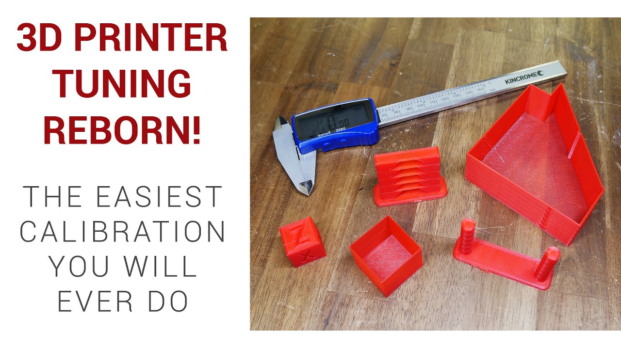
3D printer calibration revolutionised - Step by step to better print quality
992.9K
Stepper motor driver current tuning sets the correct current for your particular stepper motors and printer. If your printer is running fine and motors aren't too hot to touch, this step isn't necessary. Only perform this if experiencing skipped/missed steps or if motors are burning up. Significant changes like heavier beds or converting from bowden tube to direct drive also warrant this check. The rule of thumb: if missing steps, increase current; if motors are burning up, decrease current. The page covers both types of drivers—those requiring physical adjustment of a trim pot on top of the driver, and newer ones adjustable via G-code. Videos are pre-cued to demonstrate the process for each type.
Click to watch →
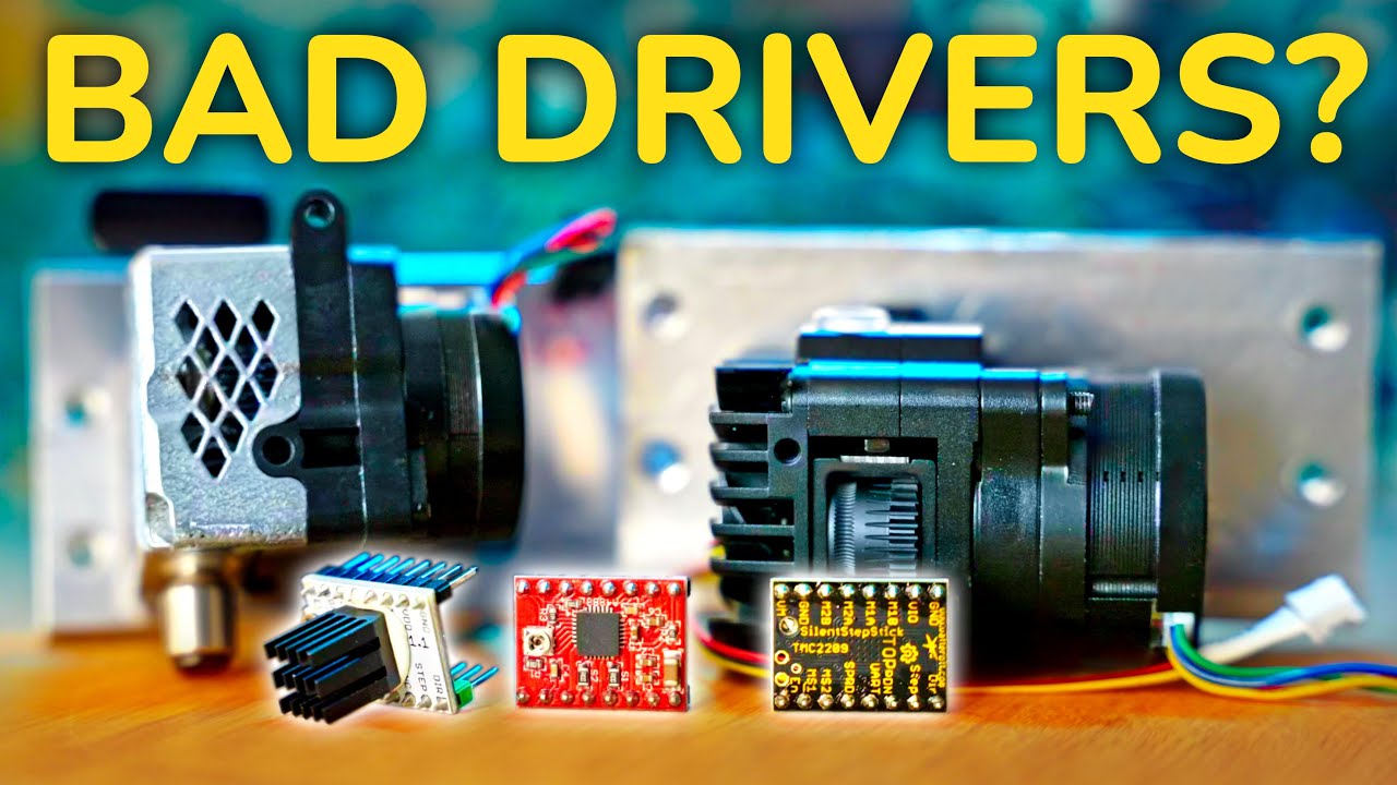
Are you using your stepper drivers wrong? E3D Revo Roto Retested!
66.7K
Different stepper drivers control motor current differently. Trinamic drivers (TMC2208, TMC2209) allow direct current setting via reference voltage, with the driver supplying the motor with that amount of current. The A4988 driver does not have direct current control—its reference voltage sets only the momentary peak current at which the internal PWM chopper turns off, after which current drops through the motor. This means A4988 results have less current flowing through the motor than Trinamic drivers at the same reference voltage setting. Understanding these differences is crucial for accurate extruder testing and comparison.
Click to watch →

Ramps 5 of 5 - stepper drivers
14.3K
Trinamic's TMC2100 introduced StealthChop, changing from voltage-based to current-based driving for significantly lower noise. The driver supports traditional drive mode and SpreadCycle (advanced voltage drive). TMC2100 is basic replacement for Pololu drivers; TMC2130 adds stall guard and software end stops; TMC2208 offers UART serial configuration with StealthChop2 (improved algorithm) and higher current capability. All use software-generated microstep tables (multipliers rather than native microstepping), enabling smooth quiet operation without extremely high pulse rates. This allows high-speed printing using quarter stepping with software interpolation, avoiding resonance problems and processor limitations. Vockrodt's StepStick design inverts traditional layout, placing driver on bottom so thermal vias transfer heat to top ground plane for easier heatsink mounting, though two-layer design is suboptimal for size constraints.
Click to watch →
Deep Dive
Configuring CNC firmware (such as GRBL or Marlin) with appropriate steps-per-millimeter and acceleration profiles.

✅ Configurar parametros de su CNC ( GRBL ) #8b
537.7K
This video explains how to configure GRBL CNC machine parameters, including calculating steps per millimeter by dividing 360° by the motor's step angle (e.g., 360/1.8 = 200 steps per revolution) and then dividing by the lead screw pitch (e.g., 200/8mm = 25 steps/mm for a 4-thread screw), configuring velocity and acceleration through testing to prevent step loss, and setting other parameters like pulse width, delay, acceleration, units, and endstop masks for optimal CNC machine operation.
Click to watch →
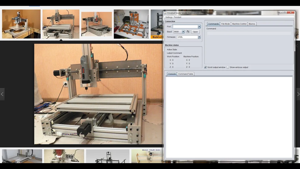
Tutorial CNC 2 - Configurando o GRBL
118.6K
This tutorial explains how to configure GRBL, an open-source CNC controller for Arduino, by setting up communication with GCode Sender software and configuring key parameters including steps per millimeter (calculated from motor steps per revolution, microstepping, and lead screw pitch), feed rates, acceleration, and soft limits to ensure accurate and safe CNC machine operation.
Click to watch →
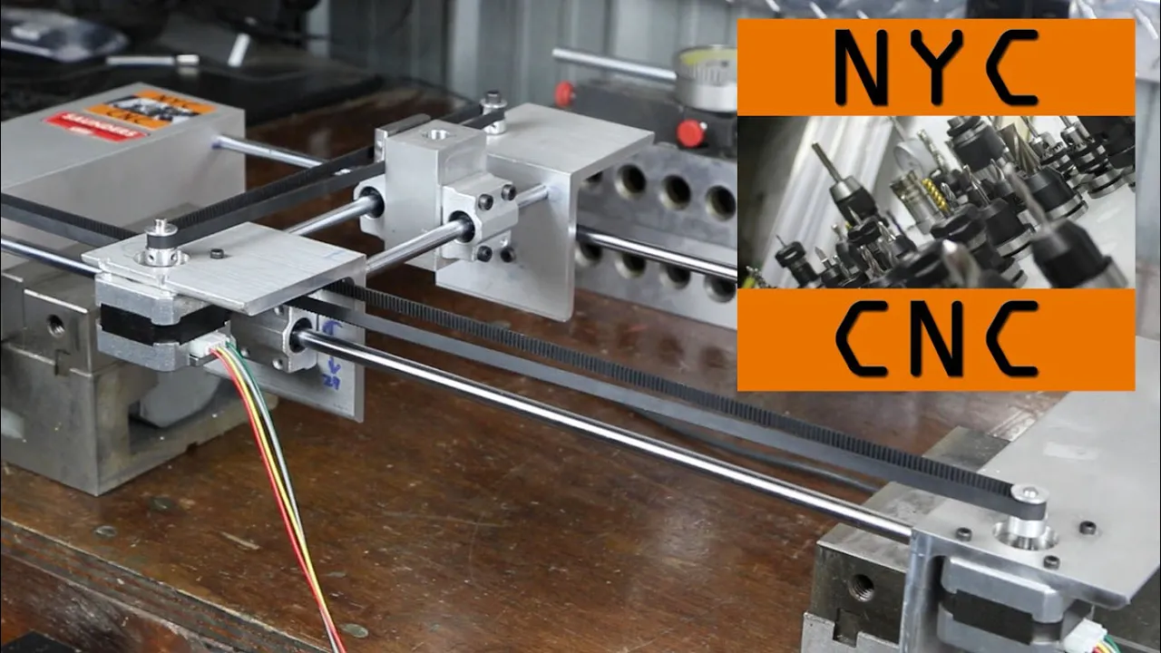
DIY Cheap Arduino CNC Machine - Machine is Complete AND Accurate!
1.9M
This segment covers configuring the GRBL shield parameters for proper machine operation. The presenter explains that GRBL parameters control step settings, acceleration, and feed rates. They demonstrate calculating step settings from pulley diameter using the formula pi times diameter times revolutions, converting the measured 1.256 inches per revolution to 6.269 steps per millimeter. The presenter configures parameters 0 and 1 for X and Y axes, and adjusts parameters 3, 4, 5, and 8 for acceleration and maximum feed rate. They test accuracy by moving to X-20 and verifying with a dial indicator, achieving 0.786 inches (within 1/1000 of an inch of target), demonstrating excellent accuracy for an inexpensive machine.
Click to watch →
Marlin v1.1.8 3D Printer Firmware Complete Config - 2018 - Chris's Basement
102.1K
Marlin is the most popular 3D printer firmware, written in C for Arduino-based boards. Configuration requires Arduino IDE as editor and compiler. Download latest Marlin (1.1.8), extract, and open Marlin folder. Two main files: configuration.h and configuration_adv.h. Key settings include: configuration version, author info, boot screen, serial baud rate (250,000), board selection (e.g., Ramps 1.4 EFB = board 43), custom machine name, extruder count, filament size (1.75mm), power supply type (0=default, 1=ATX, 2=Xbox 360), thermistor selection (type 1 default), temperature sensors, max temperatures (255°C hot end, 130°C bed), PID settings with M303 auto-tune, extruder min temp (170°C), max extrusion length, thermal runaway protection, end stops (min for Cartesian), pull-up resistors, inverting settings (check with M119), E-steps (100 for direct drive), X/Y steps (100 with 16-tooth pulleys), Z-steps (2560 for 8mm rod, 4000 for M5 rod), feed rates (200mm/s X/Y, 20mm/s Z), acceleration, jerk settings, build volume (250x210mm), software end stops, LCD controller type (RepRapDiscount), and baby stepping for first layer adjustment.
Click to watch →
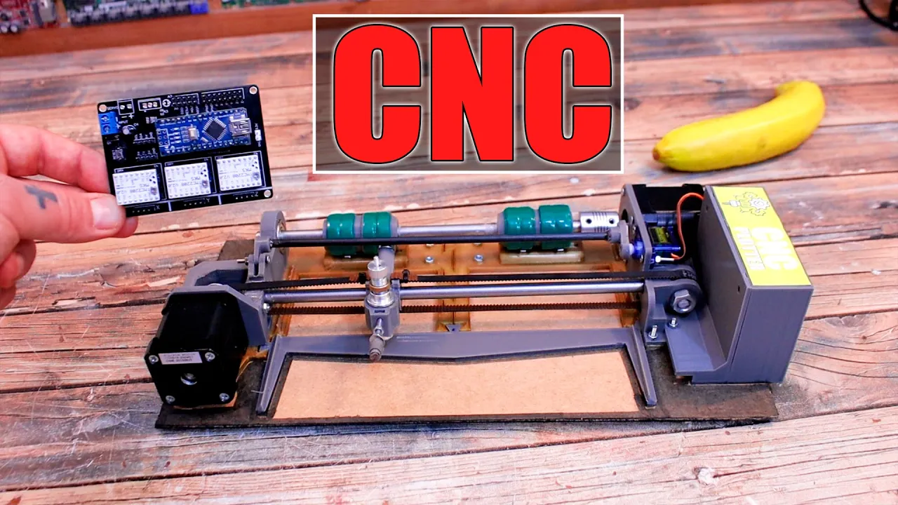
GRBL PCB Shield - CNC Plotter | Vinyl Cutter
158.1K
Proper CNC operation requires configuring GRBL settings for accurate movement. Users access settings via console commands ($$), then calculate steps per millimeter based on measured pulley and barrel diameters. Configuration involves setting $100=value for X-axis and $101=value for Y-axis. Additional setup includes uploading GRBL firmware to Arduino Nano and calibrating servo angles in spindle_control.c for precise blade positioning. These advanced configurations ensure the machine executes G-code commands accurately, transforming digital designs into physical cuts.
Click to watch →
Performance
Performance
2:01- 1
Musical segment with audience interaction.
- 2
Engaging live performance atmosphere.
- 3
Highlighting key musical moments.
Digital Current Control and Closed-Loop Systems: Moving Beyond Manual Vref Calibration
While calibrating the Vref on manual stepper drivers like the A4988 is a traditional method in DIY CNC building, modern motion control has largely shifted toward software-controlled drivers (such as Trinamic TMC series) and closed-loop stepper systems. Critics of manual Vref calibration point out that using a physical screwdriver and multimeter on a live board is highly prone to human error, often resulting in accidental short circuits that destroy the driver. Furthermore, A4988 drivers lack advanced thermal management and produce significant high-frequency noise. In contrast, modern TMC drivers allow users to configure current digitally via firmware (using UART or SPI), offering silent operation and automatic current scaling. Additionally, closed-loop stepper motors dynamically adjust current based on real-time feedback, rendering static Vref calibration obsolete. Advocating for manual A4988 tuning is increasingly viewed as promoting an outdated, risky, and inefficient practice when safer, software-defined alternatives are readily available.
Understanding of Ohm's Law and basic electrical concepts such as voltage, current, and resistance.
Fundamental working principles of bipolar stepper motors, including phases, steps, and holding torque.
The role of a stepper motor driver (specifically the A4988) in controlling current flow to motor coils.
Basic proficiency in using a digital multimeter (DMM) to measure DC voltage safely.
Configuring microstepping resolutions (e.g., 1/16 step) on the A4988 using MS1, MS2, and MS3 pins.
Implementing thermal management strategies, such as heatsinks and cooling fans, to prevent driver overheating.
Exploring more advanced, silent stepper drivers like the TMC2208/TMC2209 and their software-defined current tuning.
Configuring CNC firmware (such as GRBL or Marlin) with appropriate steps-per-millimeter and acceleration profiles.
51K views404likes6:18@laborjagOriginal Release: 2017-08-31
[Music] [Music] [Music] e [Music] you [Music] [Music] n [Music] n [Music] oh [Music] [Applause] [Music] oh [Music] [Music] he [Music] [Music] [Music] a [Music] oh [Music] oh [Music] [Music] n [Music] w
Up Next
31:35
GRBL and Arduino CNC Shield Setup Guide for Beginners
@diyengineers
264.6K views•2023-01-05

12:54
Triumph of Orthodoxy Icon: Byzantine Art & History Explained
@BenCallan
2.1K views•2024-08-06

9:49
FastAPI vs Flask vs Django: Choosing the Right Python Web Framework
@TechWithTim
302.5K views•2024-05-26

1:42
Game of Thrones Opening Credits: A Cinematic Analysis
@gameofthrones
46.3M views•2011-04-18
Related Study Plans & Knowledge Roadmaps
Structured learning paths in General & Interdisciplinary Studies
general-studies
Elevator Engineering: History, Physics & Cities
01From Hoists to Safety Brakes: The Dawn of Vertical Lift
02Hydraulic vs. Traction: The Engineering Physics of Elevators
03Modern Speed, Safety, and Algorithms
+ 2 more learning modules
12h5 modules
Explore Roadmap
general-studies
Rubber: Material Science, History & Geopolitics
01Origins of Natural Rubber & Mesoamerican History
02The Chemistry of Natural Rubber & Vulcanization
03The Geopolitics of the Rubber Boom & Colonization
+ 2 more learning modules
12h5 modules
Explore Roadmap
general-studies
Containerization: Evolution, Logistics & Trade
01Ancient Trade & Bulk Cargo: Amphorae to Barrels
02The Industrial Revolution & Cardboard Packaging
03The Containerization Revolution: Malcom McLean
+ 2 more learning modules
12h5 modules
Explore Roadmap
general-studies
Textile Tech: Evolution, Labor & Global Impact
01Pre-Industrial Textiles: Handloom & Cottage Industry
02Mechanization: The Spinning Jenny to the Power Loom
03The Factory System & Global Labor Transformation
+ 2 more learning modules
10h5 modules
Explore Roadmap