This video demonstrates how to calibrate a GRBL-based CNC plotter by adjusting the steps per mm parameter: after generating a 20x20mm square in Inkscape and sending it to the GRBL controller, if the printed result is significantly smaller than expected (e.g., only 5mm instead of 20mm), the steps per mm value must be increased (e.g., from 250 to 800) to achieve accurate axis movement and proper print dimensions.
How to Build a GRBL Arduino CNC Plotter with Servo Control
Added:Deep Dive
Basic understanding of the Arduino ecosystem, including how to configure the Arduino IDE, upload sketches, and utilize serial communication.

Basic concept of Arduino in Hindi | Arduino tutorials for beginners part #1
1.4M
Arduino IDE is free software available for all operating systems (Windows, Mac, Linux). Download from Arduino website by searching 'Arduino IDE' and clicking the first official option. After installation, the desktop icon launches the IDE containing: File menu (New, Open, Save), Examples menu with pre-written code templates (LED blinking, LCD interfacing, sensors), Sketch menu with Include Library for sensor commands, and Tools menu for board and port selection. For successful programming, select the correct board (Uno, Mega, Nano, Mini) and the connected serial port (e.g., COM3). The Upload button transfers programs to Arduino, enabling control of connected components like the built-in LED on pin 13.
Click to watch →
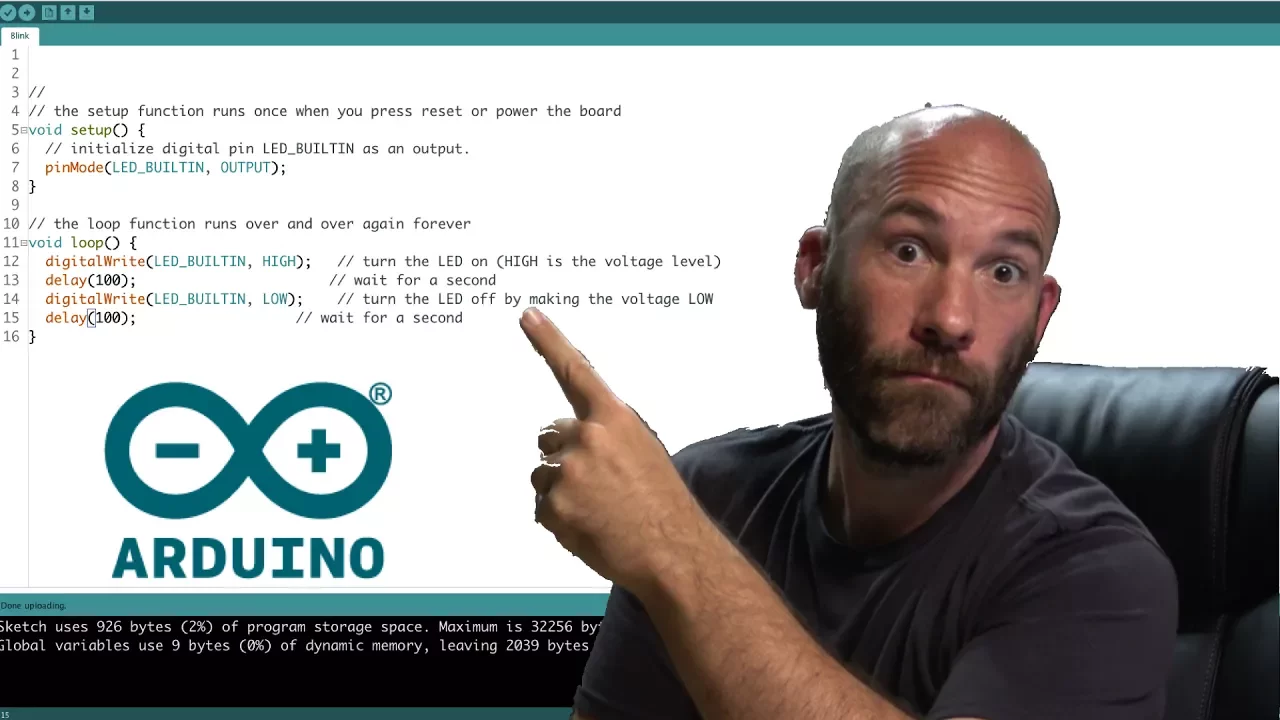
Arduino IDE Introduction
210.4K
The Arduino IDE is an integrated development environment used to write and upload code to Arduino boards, featuring essential tools like code verification, auto-formatting, serial monitoring, and serial plotting; key configurations include enabling line numbers and code folding in preferences, selecting the correct board type and COM port in the tools menu, and using the sketch menu to verify code, upload to the board, and include necessary libraries for advanced functionality.
Click to watch →

Arduino Programming Masterclass: From Basics to Libraries in 90 Mins
3.6M
The Arduino IDE enables writing and uploading code to boards. Available versions include Arduino IDE 1, Arduino IDE 2, and a web editor. Installation creates a sketchbook folder storing projects and libraries. The workflow involves: connecting via USB, selecting board type under Tools > Board, choosing COM port under Tools > Port, clicking Verify to compile and check errors, then clicking Upload. Every program requires void setup() (runs once for initialization) and void loop() (runs repeatedly forever). Variables store data using data types (boolean, byte, int, long, float, char), names, assignment operators (=), and initial values. Semicolons terminate statements. The Blink example demonstrates basic functionality by toggling the onboard LED.
Click to watch →
![Ардуино уроки программирование для начинающих с 9 лет [с нуля] #ДомаВместе](https://i.ytimg.com/vi/RwO_4nhRTUM/maxresdefault.jpg)
Ардуино уроки программирование для начинающих с 9 лет [с нуля] #ДомаВместе
114.8K
Arduino IDE is the software for writing and uploading code to Arduino boards. Download from the official website, choosing between classic installer (Windows XP+), portable version (no admin rights needed), or versions for Windows 8/10. The classic version is recommended. During installation, accept the free license agreement, select software, drivers, shortcuts, and file association for .ino files. Allocate 470-500 MB of free space. After installation, connect Arduino via USB to a computer port (prefer rear ports for better connection quality). The board's LED indicators confirm power status: 'ON' for Uno, green LED for Nano.
Click to watch →

INSTALAÇÃO DO SOFTWARE DO ARDUINO (IDE)
78.1K
This video tutorial demonstrates how to download and install the Arduino IDE software, covering both offline and online installation methods for Windows, Mac, and Linux systems. The offline installation involves downloading a ZIP file, extracting it, and running the Arduino.exe file, while the administrator installation uses the Windows installer executable. The tutorial also explains how to configure text size preferences, select the appropriate board and serial port, and upload programs using the 'Upload' button. Users can access the Blink example to test their installation by programming an LED to blink every second.
Click to watch →
Deep Dive
Fundamentals of stepper motor operation and hardware wiring, specifically how stepper drivers (e.g., A4988) regulate current and interpret step/direction signals.
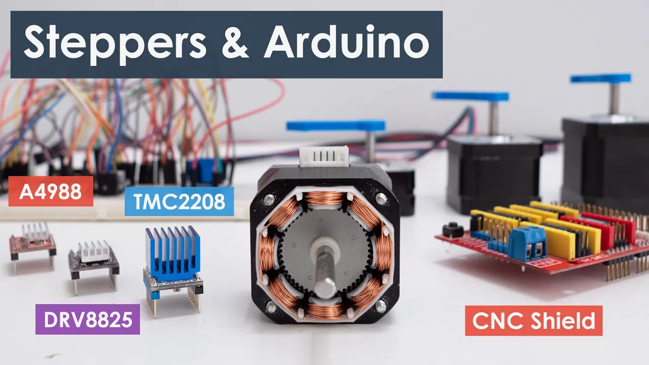
Controlling Stepper Motors with Arduino: A Guide
1.6M
This comprehensive section covers the foundational concepts of stepper motors and the A4988 driver system. Stepper motors are brushless DC motors capable of precise position control without feedback, consisting of a stator with coils and a permanent magnet rotor. The NEMA 17 is the most popular maker motor, featuring 200 steps per revolution (1.8°/step) or 400 steps (0.9°/step), with NEMA designations indicating faceplate size in tenths of inches. The A4988 driver provides current limiting via a trimmer potentiometer, with two methods for adjustment: measuring reference voltage (I = Vref/RCS) or using an ammeter in series with one coil. Motor phase identification is achieved by rotating the shaft - connecting wires from the same phase increases resistance. Microstepping increases resolution beyond basic steps, with the A4988 supporting up to 16-microstep mode (3200 steps/rev).
Click to watch →
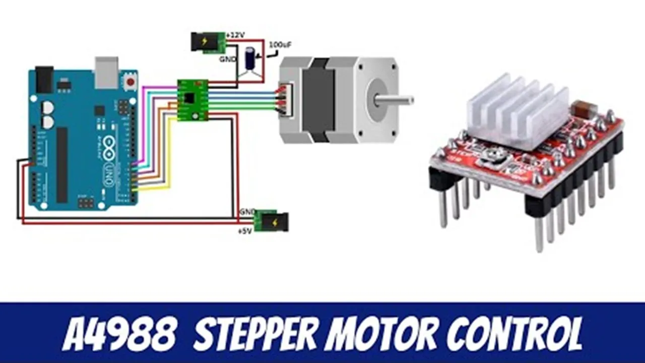
A4988 Stepper Motor Controller - Arduino & NodeMCU
165.1K
The A4988 is a bipolar stepper motor driver that controls motor operation through multiple configurable pins. Key components include: Enable pin for disabling the driver, MS1-MS3 pins for selecting microstepping modes (full, half, quarter, eighth, sixteenth steps), Reset/Sleep pins for power management, Step pin for triggering individual motor steps, and Dir pin for controlling rotation direction. The driver accepts motor voltage input (8-35V) and requires separate 3-5.5V logic power. The onboard potentiometer controls current limit through Vref reference voltage, calculated as motor rated current divided by 2.5 ohms. The driver can handle up to 1A per phase without cooling, increasing to 2A with proper heatsinking. Proper configuration ensures safe motor operation while maximizing performance.
Click to watch →

Learn to use A4988 Stepper Motor Driver
7.5K
The A4988 is a popular bipolar stepper motor driver capable of handling motors rated up to 35V and 2A; it operates by receiving 5V logic signals on the step and direction pins, where each step pulse rotates the motor one step in the direction determined by the direction pin (ground for anti-clockwise, +5V for clockwise), and features microstepping modes controlled by the MS1-MS3 pins along with a potentiometer for setting current limit to protect both the driver and motor.
Click to watch →
Coordinated stepper motor control (arduino)
367.7K
The A4988 stepper motor driver simplifies controlling stepper motors by requiring only two control pins per motor: direction and step. The direction pin determines rotation direction (high or low), while the step pin triggers individual steps when taken high. The enable pin can be held constant as it doesn't require intelligent signaling. This reduces the number of Arduino pins needed from four to two per motor, enabling control of multiple motors with fewer resources. The speed is inversely proportional to the interval between step pulses, meaning shorter delays between pulses result in faster motor movement.
Click to watch →

Arduino CNC Shield V3 and A4988 Hybrid Stepper Motor Driver, CNC Shield pinout, wiring, code, DIY
241.4K
The A4988 is a complete microstepping motor driver with built-in translator for bipolar stepper motors, supporting full, half, quarter, eighth, and sixteenth step modes with 35V/±2A capability. Key pins include: Ground and VDD (3-5.5V for driver power), 1A/1B and 2A/2B (connect to bipolar motor coils), Ground and VMOT (2-35V motor power with 47μF decoupling capacitor recommended), STEP and DIR (control motor movement with one pulse per microstep), SLEEP (power-saving mode), RESET (translator home state), MS1/MS2/MS3 (microstep resolution selection with internal pulldowns), and ENABLE (output enable/disable). The internal translator eliminates complex programming requirements.
Click to watch →
Deep Dive
Introduction to coordinate geometry and Cartesian coordinates (X, Y, and Z axes) as they relate to physical machine movement.

Machine and Work Coordinate System (aka: how the heck do I teach my machine the part location?)
223
The Cartesian coordinate system is a 3D grid used to define positions in CNC machining with X (horizontal), Y (vertical), and Z (depth) axes. Positive values indicate movement in one direction, while negative values indicate the opposite. The system is divided into four quadrants. Machine travel defines the work envelope: X travel (sideline to sideline), Y travel (endzone to endzone), and Z travel (tool height). Understanding which quadrant you're in is essential for accurate programming and setup.
Click to watch →

നമുക്ക് പരിചയപ്പെടാം CNC മെഷീൻ ആക്സിസ് Detailed Explanation,Check the Description box.
672
CNC machines use three primary coordinate axes: X-axis (left-right movement), Y-axis (front-back movement), and Z-axis (vertical up-down movement). When facing the machine, the left-right direction is the X-axis, the front-back direction is the Y-axis, and the vertical direction is the Z-axis. Each axis has positive and negative directions for precise positioning.
Click to watch →

clase cecati 8-- 17 diciembre 2020
135
CNC machines use a three-dimensional coordinate system with X, Y, and Z axes. The X-axis controls longitudinal movement (left to right), the Y-axis controls transverse movement (perpendicular to X), and the Z-axis controls vertical movement (up and down). Understanding these coordinates is essential for programming tool movements.
Click to watch →
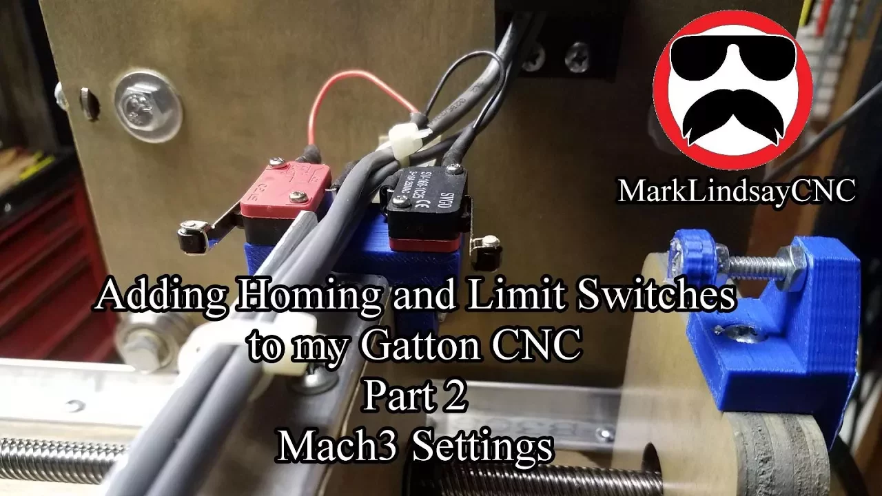
Adding Limit Switches to my Gatton CNC - Part 2
37.7K
The Cartesian coordinate system is the standard reference system for CNC machines. X-axis represents left-to-right motion (positive to the right, negative to the left). Y-axis represents front-to-back motion (positive toward the back of the machine, negative toward the front). Z-axis represents up-down motion (positive upward, negative downward). Coordinates are always expressed in the order X, Y, Z. This system is similar to military map reading conventions and forms the foundation for all CNC programming and coordinate calculations.
Click to watch →

PHYSICS 01 | CHAPTER 01| LESSON (07) |. Cartesian coordinate. الإحداثيات الكارتيزية .
36.7K
The Cartesian coordinate system is used for studying objects moving in straight lines. It consists of three perpendicular axes (X, Y, Z) that intersect at a fixed origin point. To find coordinates of a point: drop perpendicular lines from the point to each axis to measure the distance from the origin. The position vector (r) describes the location of an object and is represented as r = x·i + y·j + z·k, where x, y, and z are the coordinates along each axis.
Click to watch →
Deep Dive
Basic knowledge of servo motor mechanics and how they differ from stepper motors in terms of control signals (PWM) and positional feedback.

Servo Motor and Stepper Motor Difference
74.5K
Servo motors and stepper motors differ significantly in power supply (servo works on AC/DC, stepper only DC), control method (servo uses closed-loop with encoder, stepper uses open-loop), rotor poles (servo 10-20, stepper 200-400), rotational speed (servo 3000-6000 RPM, stepper 1000-2000 RPM), size availability (servo wide variety, stepper limited), lifespan (servo shorter due to brush replacement, stepper longer), complexity (servo complex, stepper simple), cost (servo expensive, stepper economical), performance (servo better under constant loads but hunts during positioning, stepper better under fluctuating loads), efficiency (servo highly efficient, stepper less efficient), and reliability (servo less reliable due to encoder failure risk, stepper more reliable). Servo motors are used in robotics, packaging machines, and medical devices, while stepper motors are preferred in 3D printers, semiconductor equipment, and security systems.
Click to watch →
![[산요전기코리아] 서보모터와 스텝모터의 차이점](https://i.ytimg.com/vi/zQ5cYtn_PpM/maxresdefault.jpg)
[산요전기코리아] 서보모터와 스텝모터의 차이점
63.2K
Stepping and servo motors are both used for high-precision position control in semiconductor and display equipment. Stepping motors use two offset toothed rotors with magnets, operating via open loop control without feedback, moving 50 micrometers per pulse (200 pulses/rev). Servo motors have a magnetized rotor with encoder feedback, using closed loop control that automatically corrects position errors, achieving 0.0076 micrometers per pulse (13,172 pulses/rev). Stepping motors suit simple applications without position correction needs, while servo motors excel in high-precision position and speed control.
Click to watch →
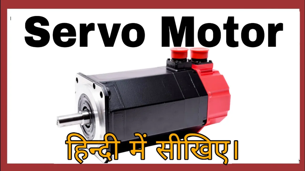
Servo Motor- Working, Construction, Types, Uses and Controller in Hindi. Servo Mechanism
190.8K
Servo motors use a closed-loop control system with feedback, which is the key difference from normal motors. A position sensor (encoder or potentiometer) is connected to the motor shaft to provide continuous feedback to the controller. The controller compares the actual position with the commanded position and adjusts the motor accordingly. When the motor receives a stop command, the controller cuts power and simultaneously activates a brake system to prevent the motor from continuing to rotate due to inertia. This feedback mechanism enables precise positioning and reliable stopping at exact angles.
Click to watch →

دورة اردوينو :: الدرس 10- محرك السيرفو و الاردوينو / How to Control Servos | Arduino Tutorial
72.7K
A servo motor is a DC motor with an electronic control circuit that provides precise control over rotation direction and angular position. It contains a gear box that converts motor speed into high torque with precise, stable movement. There are two types: standard servo motors rotate from 0 to 180 degrees, while continuous rotation servos rotate from 0 to 360 degrees. Control is achieved through PWM signals where pulse width determines position: 1ms = 0 degrees, 1.5ms = 90 degrees. The system uses closed-loop feedback with a potentiometer that produces voltage proportional to position, compared against a reference voltage to ensure accurate positioning and automatic correction of overshoot.
Click to watch →
Servo Motor vs Stepper Motor | Difference Explained in 10 Minutes | Rishabh sir (A.E.) #rishabhsir
9.3K
Stepper and servo motors are application-based motors used in electronics and electrical engineering. Stepper motors operate on open-loop control without feedback, making them cheaper and smaller but with higher error rates. Servo motors use closed-loop control with internal feedback, providing lower error but higher cost and larger size. Stepper motors provide high torque at low speeds but low torque at high speeds, while servo motors exhibit the opposite characteristic. Stepper motors lack encoders and gear boxes, while servo motors include both for precise speed and position control.
Click to watch →
Prerequisite Knowledge
- Concept 01Basic understanding of the Arduino ecosystem, including how to configure the Arduino IDE, upload sketches, and utilize serial communication.
- Concept 02Fundamentals of stepper motor operation and hardware wiring, specifically how stepper drivers (e.g., A4988) regulate current and interpret step/direction signals.
- Concept 03Introduction to coordinate geometry and Cartesian coordinates (X, Y, and Z axes) as they relate to physical machine movement.
- Concept 04Basic knowledge of servo motor mechanics and how they differ from stepper motors in terms of control signals (PWM) and positional feedback.
Subsequent Learning
- Step 01Advanced G-code generation and vector path planning using Computer-Aided Manufacturing (CAM) tools such as Inkscape, LaserGRBL, or Fusion 360.
- Step 02Transitioning from a 2D plotter to a true 3D CNC router or mill by replacing the servo Z-axis with a leadscrew-driven stepper motor axis.
- Step 03Integrating solid-state laser modules and mastering GRBL's laser mode ($32) for variable-power raster and vector engraving.
- Step 04Mathematical calibration of step-per-millimeter settings ($100, $101, $102) and optimization of maximum feed rates and acceleration parameters to prevent frame vibration.
Grbl Setup
Inkscape Ext
Calibration
Step Tuning
Grbl Setup
3:16Playing Section
- 1
Download and unzip grbl firmware files.
- 2
Copy the mi_grbl folder into Arduino libraries.
- 3
Load the firmware via Arduino IDE board settings.
Limitations of RC Servo Z-Axes and the Case for Stepper or Solenoid Actuation in CNC Plotters
While using a cheap RC servo motor for the Z-axis in an Arduino GRBL plotter is popular for beginners, it introduces significant technical limitations. Standard GRBL firmware is natively designed for stepper motors, meaning servo control requires custom, often buggy forks of the firmware that manipulate PWM signals. RC servos lack feedback to the controller, are prone to jitter, have limited lifespan under continuous use, and offer poor control over pen pressure, leading to uneven lines or damaged pen tips. Critics and experienced builders advocate for using a small stepper motor or a solenoid for the Z-axis. Steppers maintain compatibility with standard, unmodified GRBL, allowing for precise height calibration and speed control. Solenoids, on the other hand, offer faster, binary "up/down" transitions with simpler mechanics. Additionally, dedicated plotter-specific hardware and firmware (like EggBot or AxiDraw standards) are often recommended over adapted CNC milling firmware like GRBL for 2D plotting tasks.
Deep Dive
Advanced G-code generation and vector path planning using Computer-Aided Manufacturing (CAM) tools such as Inkscape, LaserGRBL, or Fusion 360.
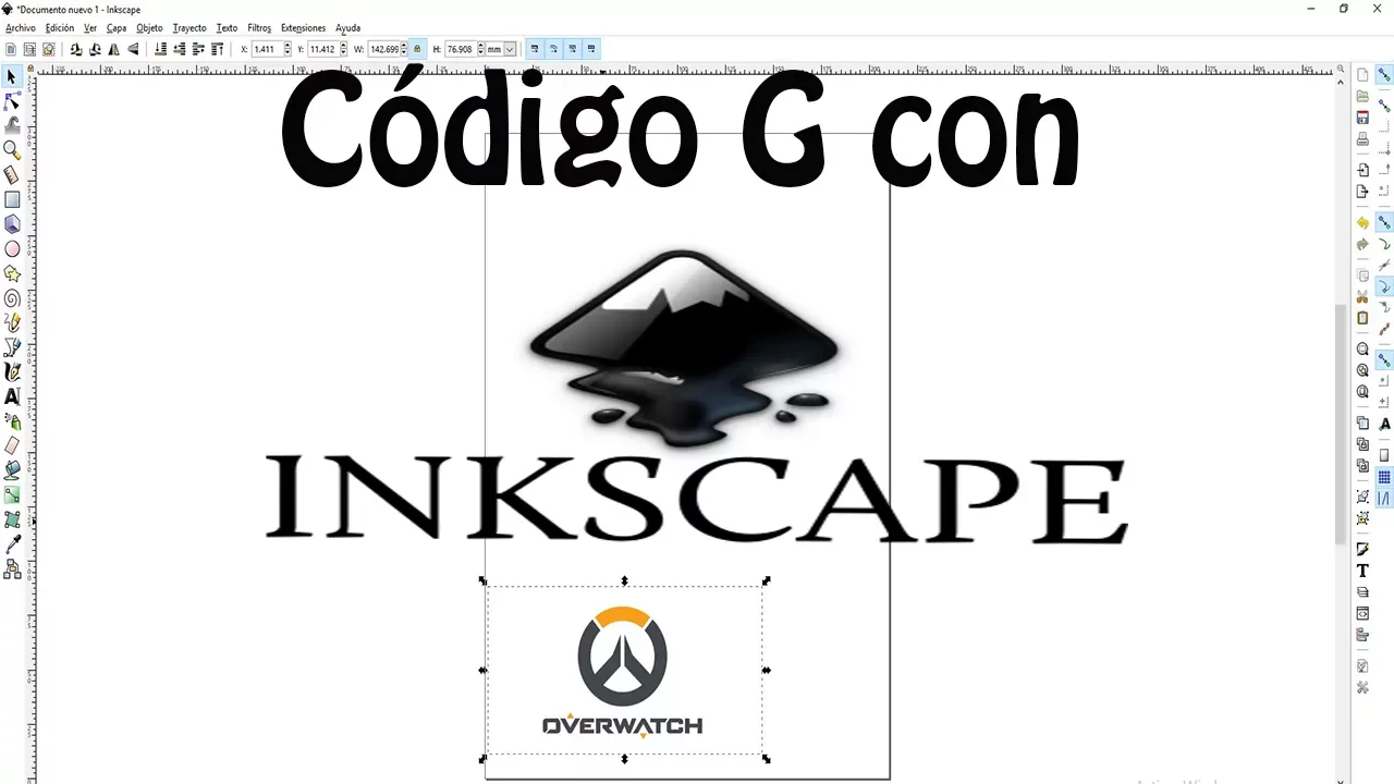
Código G con InkScape para CNC
359.3K
This tutorial demonstrates how to generate CNC G-Code for laser cutting or CNC milling by using Inkscape to vectorize an image, configure tool parameters including Z-depth, tool diameter, and step-down depth, and export the resulting toolpath as a G-Code file compatible with Universal Gcode Sender.
Click to watch →

How to use LaserGRBL to make your Laser Cut Projects
255.1K
This tutorial demonstrates how to create a laser-cut keychain using free software (Inkscape for design and LaserGRBL for cutting), covering the complete workflow from designing vector elements and raster images in Inkscape to preparing and executing the cut using LaserGRBL, including critical steps like separating cut paths from engrave areas, setting appropriate speed and power parameters, and ensuring proper file alignment.
Click to watch →

Trying Out GCodeTools (Inkscape Plugin)
53.8K
GCodeTools is a free Inkscape plugin that converts vector paths into CNC milling G-Code, enabling users to create custom name plates and pocket milling operations directly from vector designs; the plugin requires setting orientation points, surface height, Z depth, and tool parameters before generating cutting paths, with additional options for area-based pocket milling that removes material from enclosed regions.
Click to watch →

CNC Pen Plotter From Old CD Drives - A Step By Step Guide
13.4K
This extensive segment covers the complete software workflow for CNC plotting. GRBL firmware (from GitHub) runs on the Arduino to interpret G-code commands, requiring modification by replacing spindlecontrol.c/h files for servo integration. Migrbl extension for Inkscape converts vector paths to CNC-compatible G-code with integrated servo commands. LaserGRBL serves as the lightweight G-code sender interface. The complete workflow involves: creating graphics in Inkscape (setting millimeter units, converting text to paths, tracing bitmaps), applying the Migrbl extension to generate G-code with M3/M5 commands, loading into LaserGRBL, and connecting to the CNC machine. Address common issues: flipped coordinates, reversed axis directions (fix by swapping motor cables), and optimal voltage balancing performance versus motor heating. Allow cooling time between drawings to prevent overheating.
Click to watch →
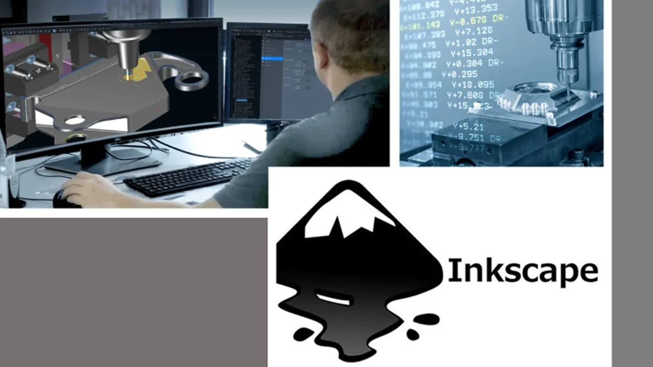
Usar Inkscape para generar GCode (CAM)
18.6K
This section covers the complete G-Code program generation process. Users learn to configure tool parameters including diameter, feed rate, penetration rate, and angle. The process involves generating the G-Code path, understanding the visualization of toolpaths through directional arrows, and replacing the default headers and footers with standard CNC commands. Key commands include G17 (XY plane), G21 (metric units), G40/G49 (compensation cancellation), G80 (cycle cancellation), G91 (incremental coordinates), G28 (home position), M05 (spindle stop), T01 (tool selection), S4000 (spindle speed), M03 (clockwise rotation), G54 (work coordinate system), and G90 (absolute coordinates).
Click to watch →
Deep Dive
Transitioning from a 2D plotter to a true 3D CNC router or mill by replacing the servo Z-axis with a leadscrew-driven stepper motor axis.

Lathe Electronic Leadscrew Part 1: Proof of Concept
187.3K
An electronic leadscrew replaces traditional mechanical change gears in CNC lathes by using a stepper motor controlled by a microcontroller to synchronize the lead screw with the spindle, eliminating the need for manual gear changes and providing flexible, programmable thread cutting capabilities.
Click to watch →
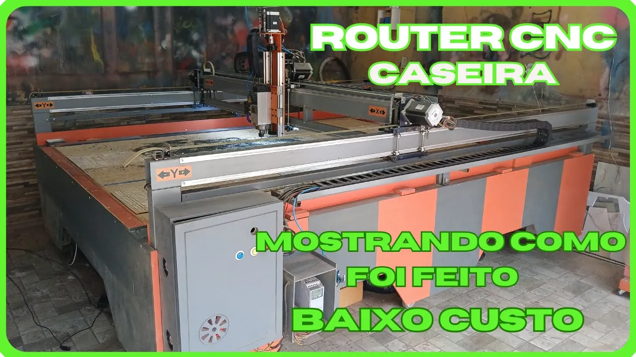
CNC ROUTER CASEIRA - MOSTRANDO COMO FOI FEITA
30.2K
The Z-axis uses a 16mm pitch, 10mm lead screw with 20mm aluminum linear guide. Initial builds use linear guides (pistons), while upgraded machines benefit from superior linear guide systems. Motor selection requires NEMA 34 stepper motors (100gf, 34oz) for X and Y axes, with the Z-axis requiring a more powerful DM8600 driver. Proper motor configuration prevents step loss. Belt tensioning uses aluminum brackets, with pulleys (20 teeth) and tensioning pulleys maintaining proper tension and eliminating play.
Click to watch →
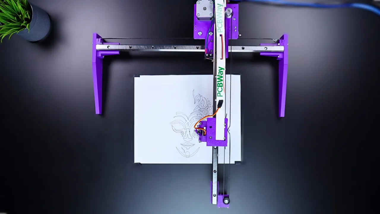
DIY 3D Printed CNC Plotter Machine with NEMA 17 Motors
107.9K
This video demonstrates how to build a 3D printed CNC plotter machine using NEMA 17 stepper motors for X and Y axes, a mini servo motor for Z-axis pen lifting, and an Atmega-based custom PCB for control; the project involves assembling 3D-printed parts, wiring electronics with limit switches, installing GRBL firmware for G-code control, and using Inkscape with a Forex Draw extension to convert images to G-code for automated drawing.
Click to watch →
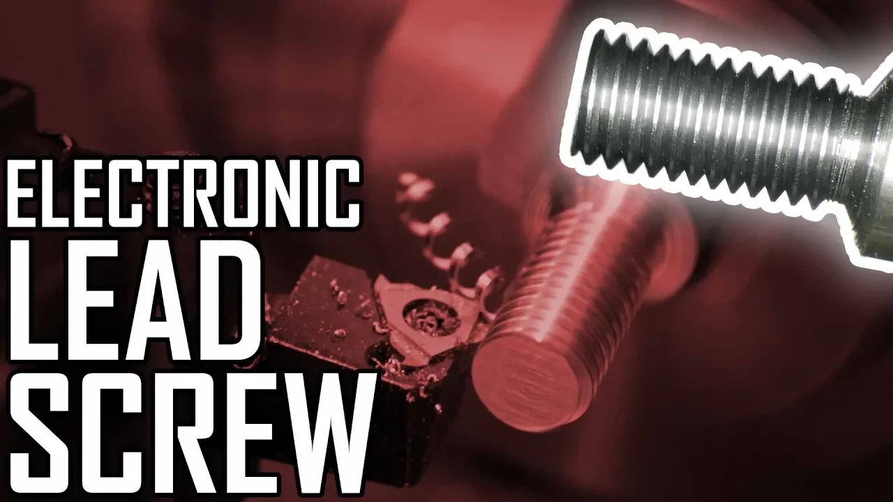
Lathe Electronic Leadscrew Part 6: First Test Cuts!
105.8K
This segment provides a detailed comparison between stepper and servo motors for the electronic lead screw application. The presenter swaps the NEMA 24 stepper for a NEMA 23 servo motor and adjusts the drive to a 3:1 belt ratio (24-tooth to 72-tooth pulleys). The presenter notes that the servo makes more noise than the stepper despite having a DSP driver, but runs cooler despite being smaller with less surface area for heat dissipation. The presenter explains that servo motors run with lower current when not needing to maintain synchronization, only peaking current when necessary. The presenter demonstrates that the servo handles the same material removal operations (cutting half-13 threads in steel) effectively, with the presenter expressing satisfaction with the servo's performance and smaller size.
Click to watch →

Ender3 V2 dual Z axis upgrade with pulley and timing belt with single stepper motor
127.7K
When upgrading to dual Z-axis, the original lead screw (36.5 cm) is replaced with a longer one (38.1 cm). The process involves placing something below the screw to hold it in place when unscrewing, then removing the original screw. The new screw must be rotated into place completely to the bottom of the step hole before tightening the bolt. Both upper and lower bolts must be tightened securely to prevent loosening during printing.
Click to watch →
Deep Dive
Integrating solid-state laser modules and mastering GRBL's laser mode ($32) for variable-power raster and vector engraving.
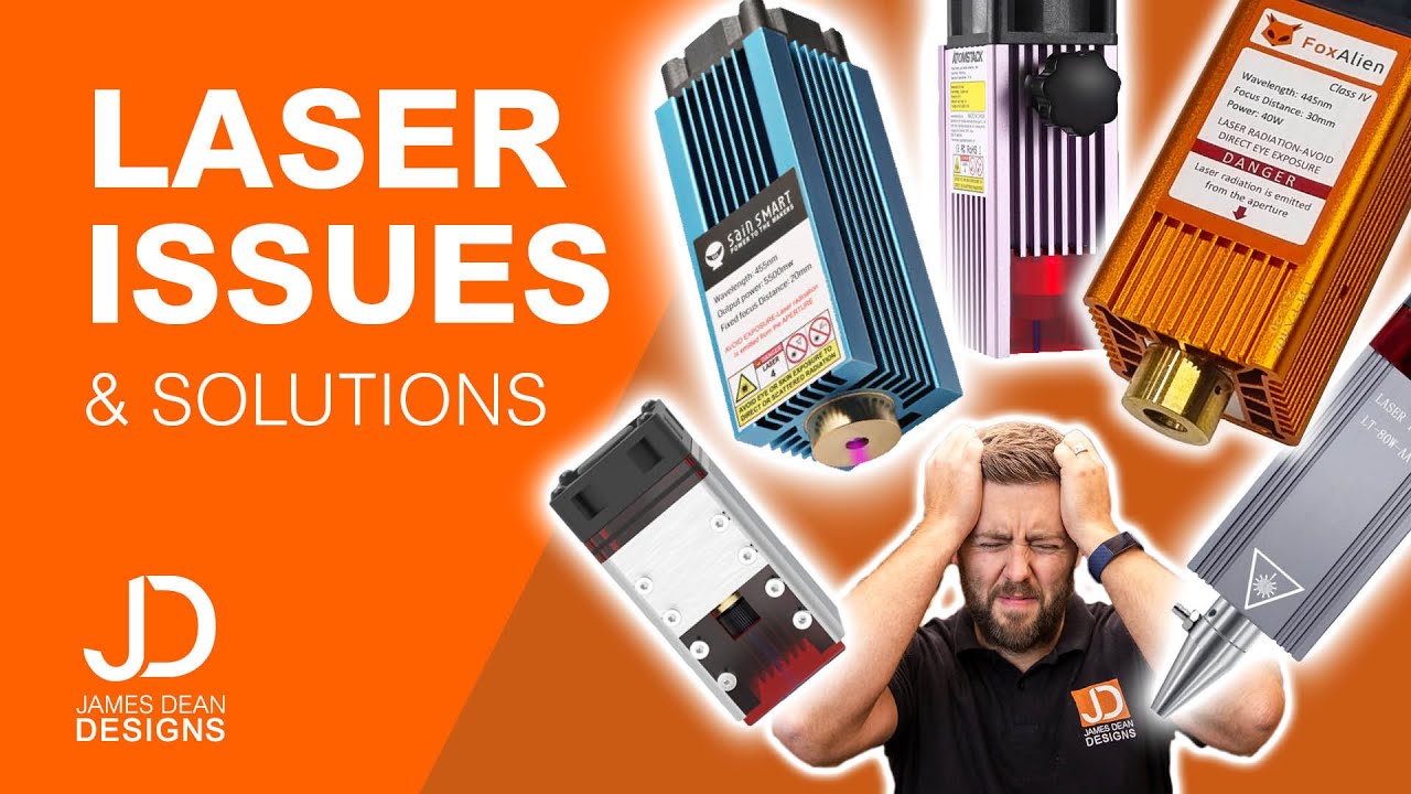
Top 10 laser issues and solutions
131.9K
The $32 GRBL setting controls whether your laser operates in 'laser mode' or continuous mode. When $32 = 0, the laser stays on continuously, creating connecting lines and burn spots. When $32 = 1, the laser turns off between passes, producing clean, separated engravings. To access this setting, you need GRBL firmware version 1.1f or higher - older versions (like 0.9) don't display these settings. You can modify $32 by typing $32=1 in Laser GRBL or LightBurn's console. This fundamental setting enables proper laser operation for desktop engraving machines.
Click to watch →

GRBL 1.1h Modo laser - Parte 1
73.6K
GRBL 1.1 introduces three new parameters for laser mode: Parameter 30 sets maximum spindle speed (maximum laser power), Parameter 31 sets minimum spindle speed (minimum laser power), and Parameter 32 enables/disables the laser module. The PWM output on pin 11 varies from 0 to 5 volts, directly controlling laser power proportionally to spindle speed settings. The M3 command activates the laser at constant power regardless of machine movement, maintaining the last configured spindle speed setting. The M4 command activates the laser with dynamic power adjustment based on machine velocity, automatically increasing power as the machine accelerates and decreasing as it decelerates. The laser only activates during cutting movements (G1, G2, G3) and not during rapid positioning (G0). To configure GRBL 1.1 for laser mode, access the configuration file (config.h) and ensure the spindle PWM variable is assigned to pin 11 (analog output) rather than pin 12 (digital output). After uploading GRBL to the Arduino, use the Serial Monitor to activate the laser module by sending 'G21=1'. To measure PWM output, connect a multimeter to pin 11 and ground, set to DC voltage measurement. The multimeter displays voltage corresponding to current laser power: 5 volts at maximum spindle speed (1000 RPM), 2.5 volts at half speed (500 RPM), and 0 volts at minimum speed. The M5 command always disables the laser. Commands G0 (rapid positioning), G80 (cancel cycle), and G38 (test move) will always disable the laser if active. The machine enters a safety mode and stops movement when laser state changes occur. Users should test both M3 and M4 modes with their specific materials to determine which produces better results for their particular application.
Click to watch →
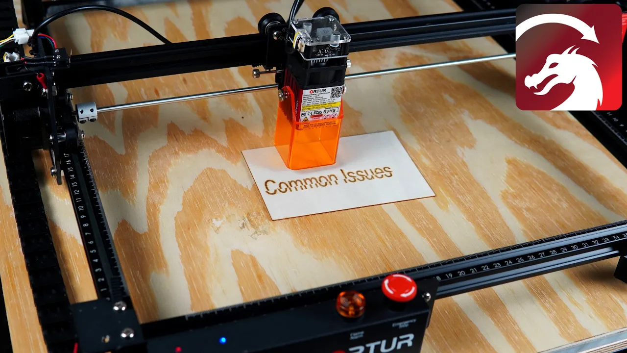
Common Diode Laser Issues & How to Troubleshoot Them
177.7K
GRBL firmware, originally designed for CNC milling machines, includes a laser mode ($32) that enables the laser to turn off during travel movements. If the laser doesn't turn off during travel, check the $32 setting by typing $$ in the console. The value should be 1 for laser mode. If it returns 0, enter $32=1 into the console and verify with another $$ command to confirm the change.
Click to watch →

3018 PRO - Setting up your laser
372K
Laser GRBL software requires installing the CH340 driver for first-time connections and enabling Z-axis controls in settings. Critical configuration involves matching the GRBL $30 setting to your test file's S-value (typically 1000) to ensure accurate power delivery. Custom buttons simplify operations including low-power focusing mode, full-power activation, and mode switching between router ($32=0) and laser ($32=1) modes.
Click to watch →

Tutorial GRBL/Primeiros passos/corte e gravação ao mesmo tempo/configuração de potência do LASER
76.7K
GRBL is a CNC software originally designed for milling machines that can be adapted for laser cutting and engraving by converting rotational speed settings to laser power percentages; to configure laser power, users must find their machine's maximum RPM setting in the GRBL configuration file (e.g., 10,000 RPM for a 10W laser module), then set the desired power percentage by dividing the target RPM by the maximum RPM (e.g., 4000 RPM represents 40% power when maximum is 10,000 RPM), with different modes available for engraving (line-by-line tracking, matrix, horizontal) and cutting (vector mode), and the software supports simultaneous cutting and engraving operations with adjustable speed, power, and pass settings.
Click to watch →
Deep Dive
Mathematical calibration of step-per-millimeter settings ($100, $101, $102) and optimization of maximum feed rates and acceleration parameters to prevent frame vibration.

UGS (GRBL) $100 $101 $102 Axis parameters and how to optimize them for your machine
4.6K
CNC machine accuracy depends on properly configuring the steps per millimeter (steps/mm) parameters ($100 for X-axis, $101 for Y-axis, $102 for Z-axis) in GRBL firmware, which can be calibrated by measuring actual travel distance against commanded distance using painters tape and vernier gauge, then iteratively adjusting these values until the machine achieves precise positioning within acceptable tolerances for the intended application.
Click to watch →

Big Tree Tech SKR 2 - Install - Marlin Configuration - Chris's Basement
76.2K
Configure steps per unit: X and Y are 100, Z is 400 (for 4mm lead screws), and E is 140 (for Mark 3 extruder at 16x microstepping). Acceleration and feed rates can be left at defaults and tuned later. Classic jerk is preferred over junction deviation for better linear advance compatibility.
Click to watch →

Montando minha CNC Caseira #8 - Tudo sobre o Grbl 0.9j Parte 1
159.3K
Parameters 100 (G100), 101 (G101), and 102 (G102) control steps per millimeter for X, Y, and Z axes respectively. This is calculated as: (steps per revolution × microstepping) / (millimeters per revolution). For a typical motor with 200 steps per revolution and 16 microstepping, the formula is (200 × 16) / (millimeters per revolution). Each axis requires its own calculation based on its lead screw pitch.
Click to watch →
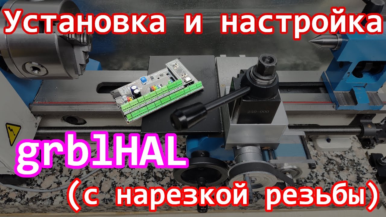
Установка и настройка grblHAL
8.9K
This section covers the critical process of tuning machine axes for optimal performance. Steps per millimeter calculation depends on motor resolution, lead screw pitch, and gear ratio—for example, a 200-step motor with 1mm lead screw yields 1000 steps/mm. Maximum speed (mm/minute) and acceleration (mm/second²) settings determine how quickly axes can move. Users start with standard values (500 mm/min, 10 mm/s²) and incrementally increase them to find maximum limits without step loss. The tuning process involves moving axes to known positions, issuing movement commands, and observing whether targets are reached. Open loop control is preferred for stepper motors as it cannot detect missed steps, requiring careful parameter tuning.
Click to watch →
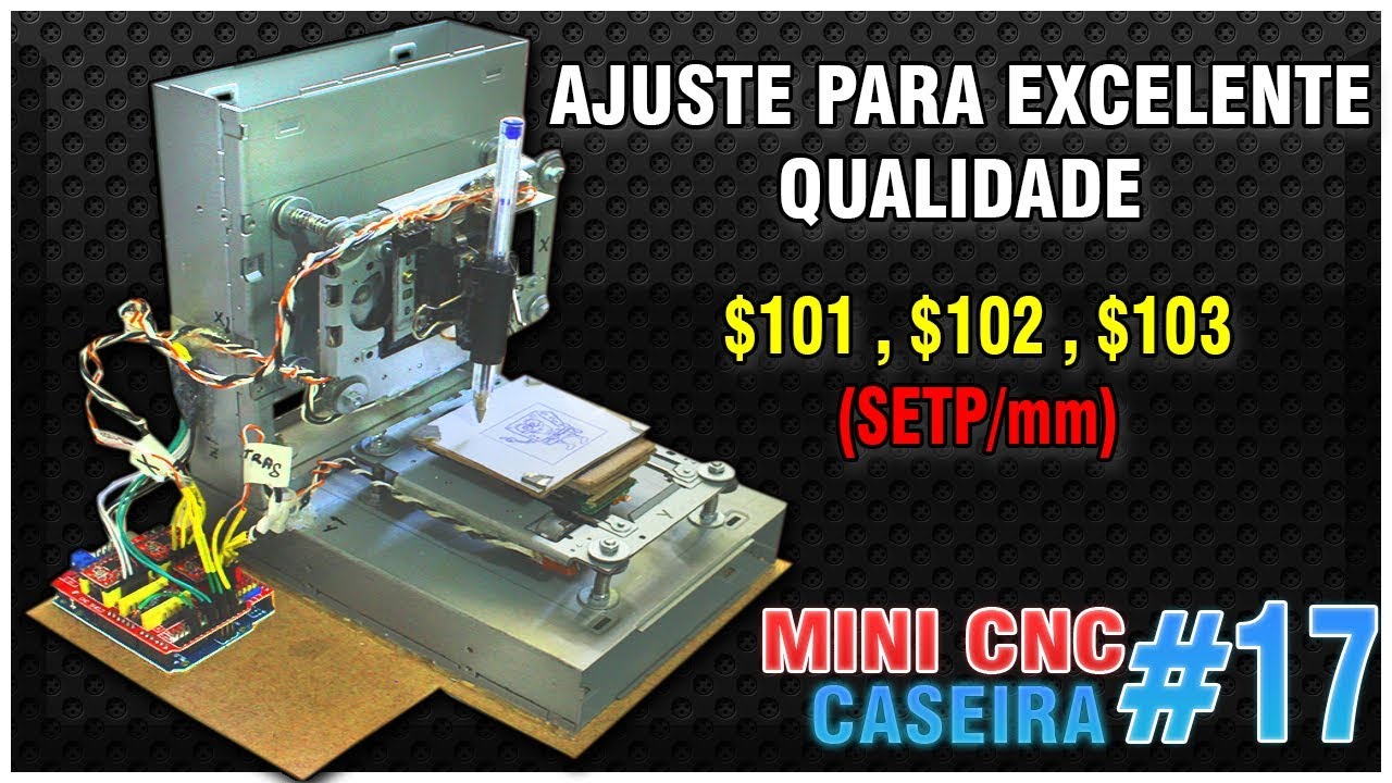
17# MINI CNC CASEIRA - AJUSTE PARA EXCELENTE QUALIDADE , step/mm ($100,$101,$102)
10.6K
The correct step/mm values can be discovered empirically through testing rather than calculation. The process involves: (1) Setting a known distance (e.g., 10mm or 1cm) in the CNC software, (2) Commanding the machine to move that distance, (3) Measuring the actual distance traveled using a ruler or caliper, (4) Adjusting the step/mm value based on the difference between commanded and actual distance. This method works because step/mm values depend on motor characteristics, lead screw pitch, and gear ratios that vary between machines.
Click to watch →
Grbl Setup
Inkscape Ext
Calibration
Step Tuning
Grbl Setup
3:16- 1
Download and unzip grbl firmware files.
- 2
Copy the mi_grbl folder into Arduino libraries.
- 3
Load the firmware via Arduino IDE board settings.
Limitations of RC Servo Z-Axes and the Case for Stepper or Solenoid Actuation in CNC Plotters
While using a cheap RC servo motor for the Z-axis in an Arduino GRBL plotter is popular for beginners, it introduces significant technical limitations. Standard GRBL firmware is natively designed for stepper motors, meaning servo control requires custom, often buggy forks of the firmware that manipulate PWM signals. RC servos lack feedback to the controller, are prone to jitter, have limited lifespan under continuous use, and offer poor control over pen pressure, leading to uneven lines or damaged pen tips. Critics and experienced builders advocate for using a small stepper motor or a solenoid for the Z-axis. Steppers maintain compatibility with standard, unmodified GRBL, allowing for precise height calibration and speed control. Solenoids, on the other hand, offer faster, binary "up/down" transitions with simpler mechanics. Additionally, dedicated plotter-specific hardware and firmware (like EggBot or AxiDraw standards) are often recommended over adapted CNC milling firmware like GRBL for 2D plotting tasks.
Basic understanding of the Arduino ecosystem, including how to configure the Arduino IDE, upload sketches, and utilize serial communication.
Fundamentals of stepper motor operation and hardware wiring, specifically how stepper drivers (e.g., A4988) regulate current and interpret step/direction signals.
Introduction to coordinate geometry and Cartesian coordinates (X, Y, and Z axes) as they relate to physical machine movement.
Basic knowledge of servo motor mechanics and how they differ from stepper motors in terms of control signals (PWM) and positional feedback.
Advanced G-code generation and vector path planning using Computer-Aided Manufacturing (CAM) tools such as Inkscape, LaserGRBL, or Fusion 360.
Transitioning from a 2D plotter to a true 3D CNC router or mill by replacing the servo Z-axis with a leadscrew-driven stepper motor axis.
Integrating solid-state laser modules and mastering GRBL's laser mode ($32) for variable-power raster and vector engraving.
Mathematical calibration of step-per-millimeter settings ($100, $101, $102) and optimization of maximum feed rates and acceleration parameters to prevent frame vibration.
585.7K views6.4Klikes11:47@MrInnovativeOriginal Release: 2017-11-14
[Music] [Music] [Applause] [Music] [Music] [Music] let's see how to add grbl film where in odd you know so you can download the RBR under the link given below in the description unzip the file copy these mi grbl folder and open your documents select add you know folder libraries and paste mi grbl folder hey over here ok so finger is added now you can load this finger to our do you know selecting your port and board correctly ok you can find it from example and mi grbl grbl upload ok simply you will compile and upload it so grbl is uploaded now we are going to add the a my inks cape extension so you have to copy this mi xscape file and paste it in the directory of Inkscape find the share folder C extension folder and paste over here also you need to copy the individual file in the extension folder okay done continue it's done our extension is added in Inkscape you can see over here mi grbl servo jet servo extension let's see how to calibrate the axis of CNC plotter so first we have to set our printing area which is 85 by 85 mm for my machine okay now I will draw a square of 20 by 20 mm 20 by 20 mm square okay object to path apply okay so G code is generated now we will open grbl controller select our proper communication port and baud rate connected we have load the grbl okay first initially we will see the basic parameters which is by default as you can see the acts steps per mm and vice steps per mm is 250 okay we will go with current setting let's see how it will came out she needn't started as we as we make our 20 by 20 mm square in inks is let's see what are the measurement over here the square is drawn is probably not 320 by 20 mm but see what are the measurements it's hardly 5mm okay so now we have to change it steps per mm for X and y-axis so once again in gr wheel controller now we are typing dollar one double zero is equal to 500 or whatever you want your step to be [Music] [Music] [Applause] this time instead looks bigger than the first one let's take the reason maybe something moving pennant but it is 110 G back then too so now let's we have said 800 steps per mm let's see okay now it looks fine this 20 by 20 mm square so 800 steps per nm is our setting [Music]
Up Next

10:06
Speech Therapy for Fluent Aphasia: Strategies & Techniques
@BurkeRehabilitation
339.4K views•2013-11-26

12:54
Triumph of Orthodoxy Icon: Byzantine Art & History Explained
@BenCallan
2.1K views•2024-08-06

9:49
FastAPI vs Flask vs Django: Choosing the Right Python Web Framework
@TechWithTim
302.5K views•2024-05-26

1:42
Game of Thrones Opening Credits: A Cinematic Analysis
@gameofthrones
46.3M views•2011-04-18
Related Study Plans & Knowledge Roadmaps
Structured learning paths in General & Interdisciplinary Studies
general-studies
Elevator Engineering: History, Physics & Cities
01From Hoists to Safety Brakes: The Dawn of Vertical Lift
02Hydraulic vs. Traction: The Engineering Physics of Elevators
03Modern Speed, Safety, and Algorithms
+ 2 more learning modules
12h5 modules
Explore Roadmap
general-studies
Rubber: Material Science, History & Geopolitics
01Origins of Natural Rubber & Mesoamerican History
02The Chemistry of Natural Rubber & Vulcanization
03The Geopolitics of the Rubber Boom & Colonization
+ 2 more learning modules
12h5 modules
Explore Roadmap
general-studies
Containerization: Evolution, Logistics & Trade
01Ancient Trade & Bulk Cargo: Amphorae to Barrels
02The Industrial Revolution & Cardboard Packaging
03The Containerization Revolution: Malcom McLean
+ 2 more learning modules
12h5 modules
Explore Roadmap
general-studies
Textile Tech: Evolution, Labor & Global Impact
01Pre-Industrial Textiles: Handloom & Cottage Industry
02Mechanization: The Spinning Jenny to the Power Loom
03The Factory System & Global Labor Transformation
+ 2 more learning modules
10h5 modules
Explore Roadmap