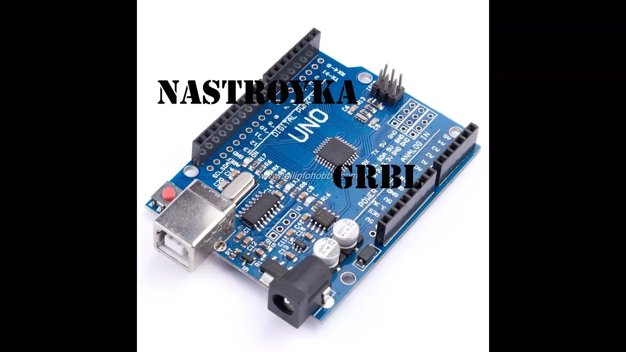





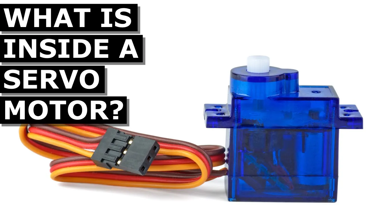












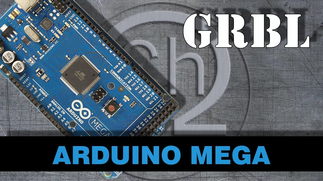


This video demonstrates how to add a hobby servo to a CNC machine controlled by an Arduino and CNC shield running grbl software by repurposing the PWM output originally used for spindle speed control; the M3, M4, M5, and S commands from spindle control are adapted to control the servo, where S values between 55-118 correspond to typical 1ms-2ms pulse widths that position the servo, though the Arduino's 8-bit PWM counter limits resolution to approximately 256 distinct positions within the 0-1000 S command range.
Integrating Servo Control with GRBL CNC: A Technical Guide
Added:Basic understanding of GRBL firmware architecture and typical CNC hardware setups.
Fundamentals of Pulse Width Modulation (PWM) and how duty cycles represent analog control signals.
Operational principles of RC servo motors, including their specific control signal requirements (pulse width and frequency).
Familiarity with standard G-code commands, specifically spindle control syntax such as M3, M5, and S-values.
Techniques for modifying and recompiling GRBL source code (such as config.h) to adjust the default PWM frequency to match standard servo requirements.
Implementing opto-isolation and dedicated power delivery circuits to prevent electrical noise from the servo affecting the CNC controller.
Configuring CAM (Computer-Aided Manufacturing) post-processors to automatically output repurposed G-code for automated Z-axis or tool-change actions.
Transitioning to advanced firmware ecosystems (like grblHAL, Marlin, or FluidNC) that natively support multi-axis control without repurposing hardware pins.
12.4K views156likes9:25Original Release: 2022-04-28
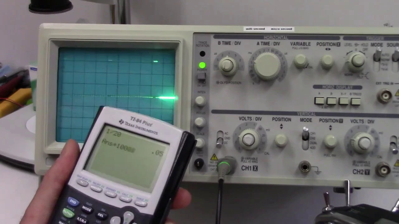
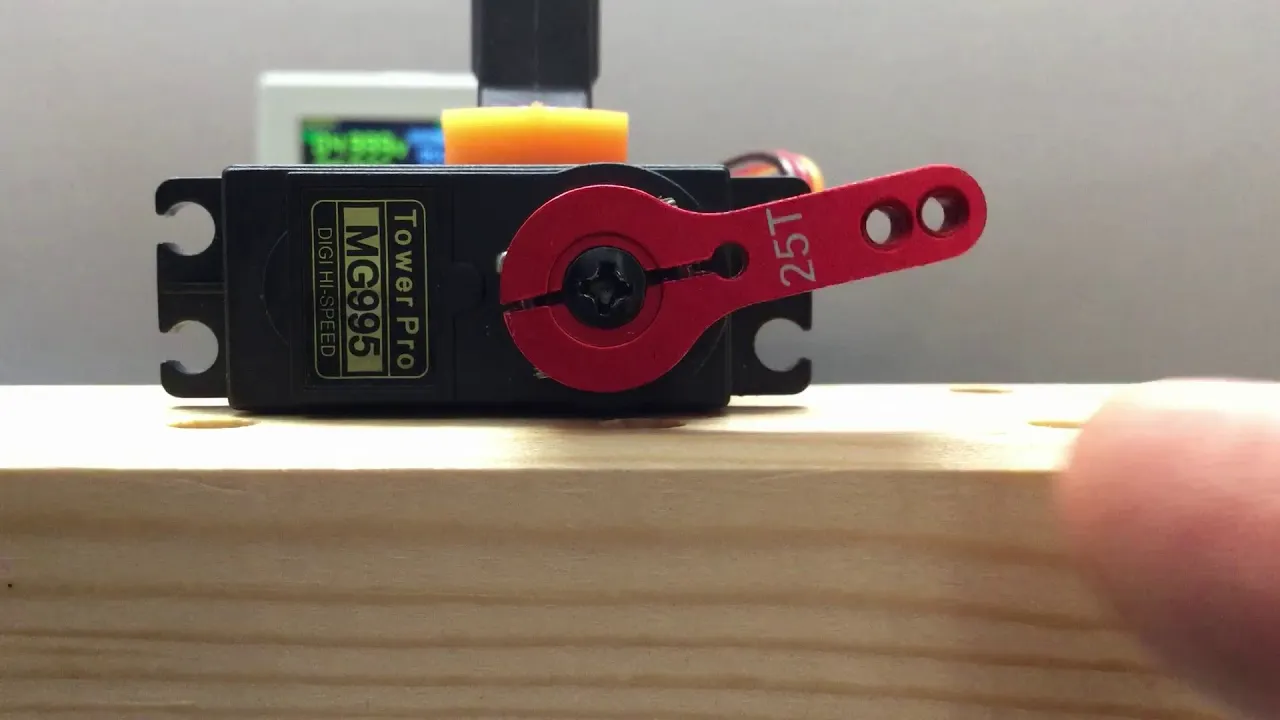
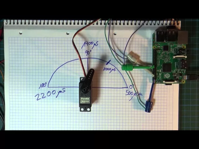
welcome to the odd jobs workshop it is possible to add a hobby type servo to a cnc machine controlled by an arduino and cnc shield running grbl software if all four stepper motor controls are in use a servo can provide an additional axis of motion or a servo can simplify the mechanical design for example some plotters use stepper motors for the x and y axes but use a servo for the z-axis to raise and lower the pen to keep this video to a reasonable length i'm directing it to folks with knowledge of arduino grbl software and the cnc shield hardware if you don't understand some parts of the video watch it again after your cnc project is farther along if you don't know how hobby servos work some parts of the video will be worth watching but if you want to directly control a server with an arduino this is not the best way to do it servo control is added by modifying and repurposing the pulse width modulation output originally intended for variable spindle speed control of cutting tools like routers as shown confirmed that variable spindle is enabled in the config.h file and make the changes to the pwm mode in the cpu map.h file note that these files are from grbl version 1.1 h the settings may be in other files in older versions the electrical connections from the cnc shield to the servo are shown the repurposing of the z plus pin is explained in the config.h file in the video i'm powering the arduino cnc shield and servo with just the usb cable a real world application may need additional power i'll be using this setup to demonstrate the control of a servo with grbl software and g-code i've added a protractor image to the servo for reference the handtech oscilloscope probes are connected to the servo control line and the spindle direction pin the hand tech displays on the ipad over wi-fi the yellow trace is a servo control signal and the blue trace is the spindle direction signal the m3 m4 m5 and the s speed value command are the four spindle speed g-code commands repurpose for servo controls before specific s commands apply to servos in general in the demo server in particular for the demo i'm just typing the commands into the arduino serial monitor on my imac but a g-code sender program can also be used i'm going through a series of g-code commands to show how easy it is to control the servo with grbl i'm starting by pressing the arduino reset button so grbl is in the lock state with no control signal of servo turns freely as usual a dollar sign x command unlocks grbl the m3 command enables the pulse width modulation output and s55 sets the pulse width modulation to a one millisecond pulse a one millisecond pulse is typical specified minimum pulse width for servos the servo will no longer turn freely and will hold that position against force if i type an s command of 118 the pulse goes to 2 milliseconds which is a typical specified maximum pulse width the one millisecond two millisecond pulse range with s between 55 and 118 isn't the hard fast rule s40 and s149 will send my servo to its full range sending another s55 command sends the servo back to the exact same position as previous as 55 commands servo commands are go to position commands not a stepper motor's move at distance commands an m5 command disables the arduino's pulse width modulation output but the arduino saves the pulse width value another m3 command re-enables the pulse with output with the save pulse width value the servo holds its position as long as there is a pulse sending m5 again stops the pulse and the servo was free to move but sending the m3 re-enable command moves the servo back to position an s command while the output is disabled saves a new pulse width value to use when the pulse output is re-enabled the command of zest0 will also stop the pulses i'm not sure which of these command combinations are useful sending m5 again to disable the output an m4 command to re-enable it just like the m3 command the m4 command enables the pulse width output but it also sets the spindle direction output high m3 sets the spindle direction output low the state of the spindle direction has no effect on the servo operation and extra m3 and m4 commands don't have any effect on the servo so the spindle direction could be used for something it's easy to add a servo to grbl based system and control it with g code but it isn't ideal the minimum pulse width modulation available from the arduino is 61 cycles per second using the measurement cursors on the oscilloscope that's the f value in the upper left corner on the oscilloscope display hobby servos typically specify 50 cycles per second the servo i'm using for this video works at 61 cycles per second but other servos may not at 61 cycles per second the time period between the start of pulses is about 16 and a half milliseconds the t value on the oscilloscope think of the s command as a percentage times 10 and s command of 500 results in a pulse of half the period about eight and a quarter milliseconds the s commands of 55 and 118 result in pulses that are 5.5 percent and 11.8 percent of 16 and a half milliseconds they're approximately the one millisecond and two millisecond commands typically given as the maximum and minimum for servo my servo has a greater pulse width range but any s command less than 40 or greater than 149 causes the servo to strain against its mechanical stops use trial and error to determine the range of any servos you use the s command range of zero to 1 000 would imply that the pulse width could change in 1000 steps but that is not true the arduino pulsewood circuitry uses an 8-bit counter so it can only have 256 values so there are only 256 possible pulse widths and many of those are outside the range of the servos dividing 1000 by 256 gives 3.9 so most of the values between 0 and 1000 are in groups of three or four consecutive values any number in a group results in the same pulse width for example starting with s55 s56 changes the pulse width and moves the servo but s57 does not s58 does not s59 does not s60 does change the pulse and moves the servo the servo speed can't be directly controlled but a series of partial steps to the next position will have the effect of slowing the motion so if you want to add a servo to your cnc project i hope you find this useful i have a few bonus tips to add the servo i used in this video was a cheap one left over from previous project but servos are available in lots of variations check out servocity.com for servos and other mechanical hardware i'm just a satisfied customer they are not a sponsor pulse width modulation has lots of uses can control the brightness of the light the speed of the motor or the temperature of the heater but pay attention to the frequency and voltage the arduino's 5 volt output might be too much for an led without a current limiting resistor and 5 volts certainly won't be enough to run a heater directly you'll need additional circuitry and the viewer might notice a light flashing with the 60 hertz frequency used for the servos here's some additional frequency settings for grbl cpu map.h file for more accurate control of a servo the arduino has a pulse with modulation function that uses its 16 bit counter but it may not be easy or even possible to use it with grbl check this link for more information on arduinos and pwm i hope this was useful thanks for watching you
Up Next

11:47
How to Build a GRBL Arduino CNC Plotter with Servo Control
@MrInnovative
585.7K views•2017-11-14

12:54
Triumph of Orthodoxy Icon: Byzantine Art & History Explained
@BenCallan
2.1K views•2024-08-06

9:49
FastAPI vs Flask vs Django: Choosing the Right Python Web Framework
@TechWithTim
302.5K views•2024-05-26

1:42
Game of Thrones Opening Credits: A Cinematic Analysis
@gameofthrones
46.3M views•2011-04-18
Related Study Plans & Knowledge Roadmaps
Structured learning paths in General & Interdisciplinary Studies
general-studies
Elevator Engineering: History, Physics & Cities
01From Hoists to Safety Brakes: The Dawn of Vertical Lift
02Hydraulic vs. Traction: The Engineering Physics of Elevators
03Modern Speed, Safety, and Algorithms
+ 2 more learning modules
12h5 modules
Explore Roadmap
general-studies
Rubber: Material Science, History & Geopolitics
01Origins of Natural Rubber & Mesoamerican History
02The Chemistry of Natural Rubber & Vulcanization
03The Geopolitics of the Rubber Boom & Colonization
+ 2 more learning modules
12h5 modules
Explore Roadmap
general-studies
Containerization: Evolution, Logistics & Trade
01Ancient Trade & Bulk Cargo: Amphorae to Barrels
02The Industrial Revolution & Cardboard Packaging
03The Containerization Revolution: Malcom McLean
+ 2 more learning modules
12h5 modules
Explore Roadmap
general-studies
Textile Tech: Evolution, Labor & Global Impact
01Pre-Industrial Textiles: Handloom & Cottage Industry
02Mechanization: The Spinning Jenny to the Power Loom
03The Factory System & Global Labor Transformation
+ 2 more learning modules
10h5 modules
Explore Roadmap