














![Klipper Resonance Compensation Overview - [input_shaper]](https://i.ytimg.com/vi/pH-1RWdC75E/hqdefault.jpg)
![Печать FPV-дронов на 3D принтере | Инженерные материалы, AI и 5 синевупов [Qidi Q2]](https://i.ytimg.com/vi_webp/2pzpUm22PnY/maxresdefault.webp)
![[EN]-GMT Connect_Webinar-Closed Loop Stepper Motor Controller](https://i.ytimg.com/vi/94I1-6-k5S0/maxresdefault.jpg)


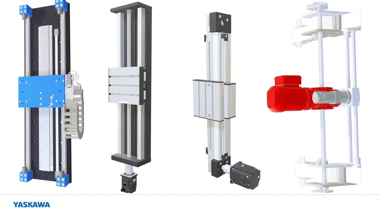
Lead screws convert rotational motion to linear motion through threaded engagement, where the lead (distance moved per revolution) determines speed and resolution; an 8mm lead screw with 2mm pitch moves 8mm per revolution, providing 0.04mm per step with a 200-step motor, which offers significantly better resolution and torque multiplication than belt systems (GT2/GT3 belts move 40-60mm per revolution, yielding 0.2-0.3mm per step), making lead screws more suitable for heavy loads like heated beds while belts are better for lighter X/Y axes in 3D printers.
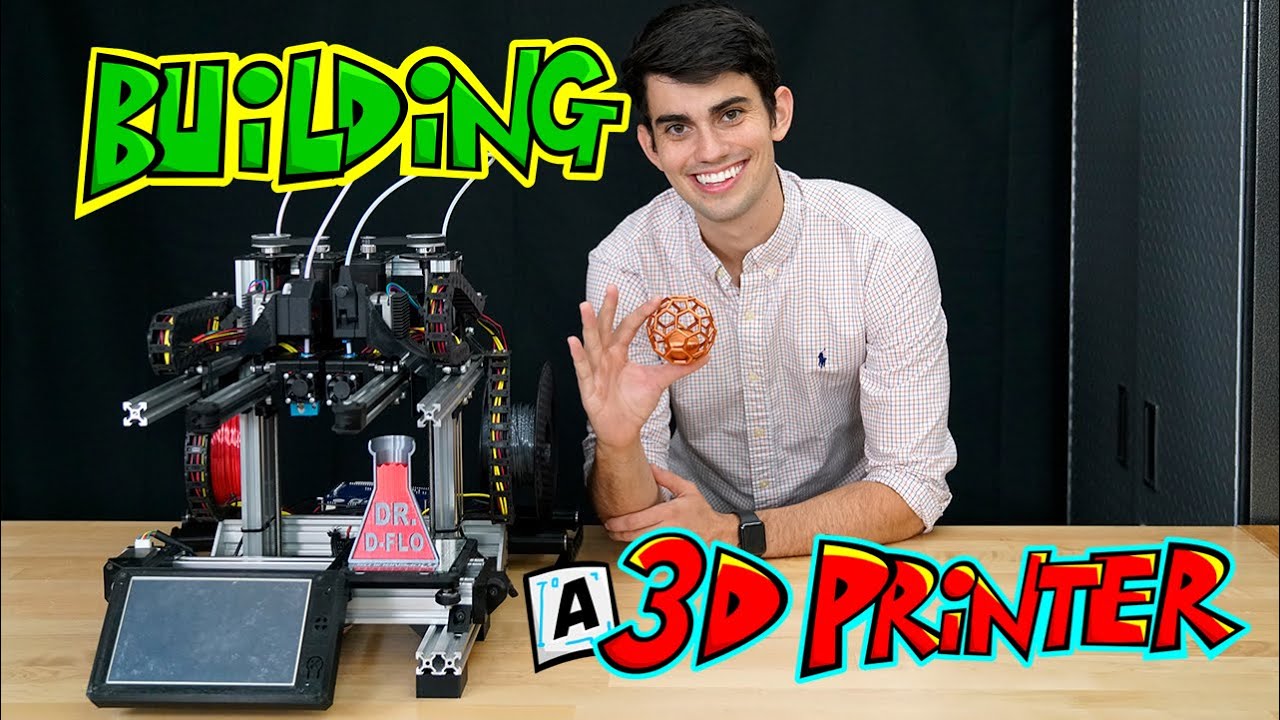
Lead Screws vs Belts: Motion Control Engineering for 3D Printers
Added:Basic physics of mechanics, specifically the conversion of rotational motion to linear motion, torque, and angular velocity.
The fundamental anatomy of a Fused Deposition Modeling (FDM) 3D printer and the roles of Cartesian axes (X, Y, and Z).
How stepper motors function, including basic concepts of steps, microstepping, and holding torque.
The definitions of precision, repeatability, and resolution in mechanical engineering, as well as the concept of mechanical backlash.
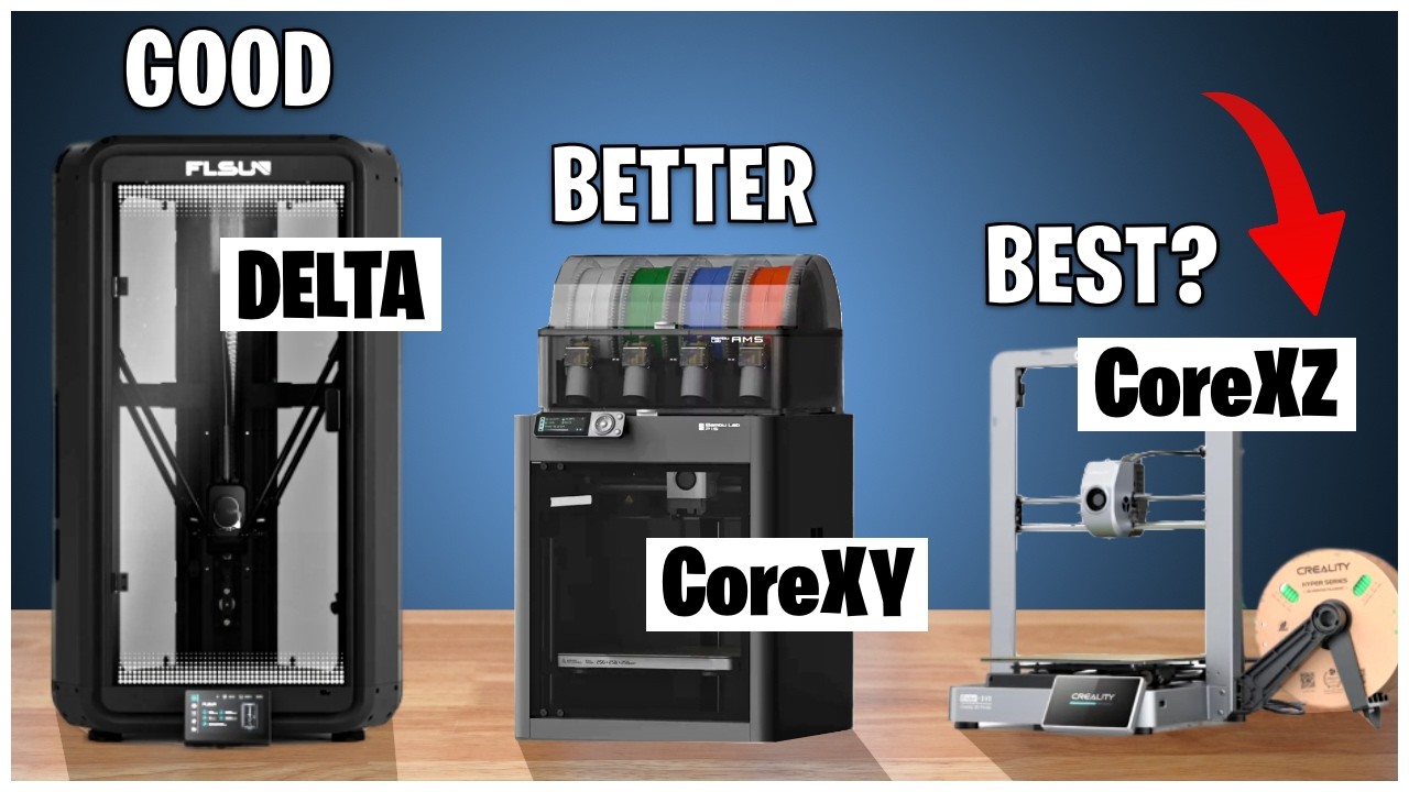
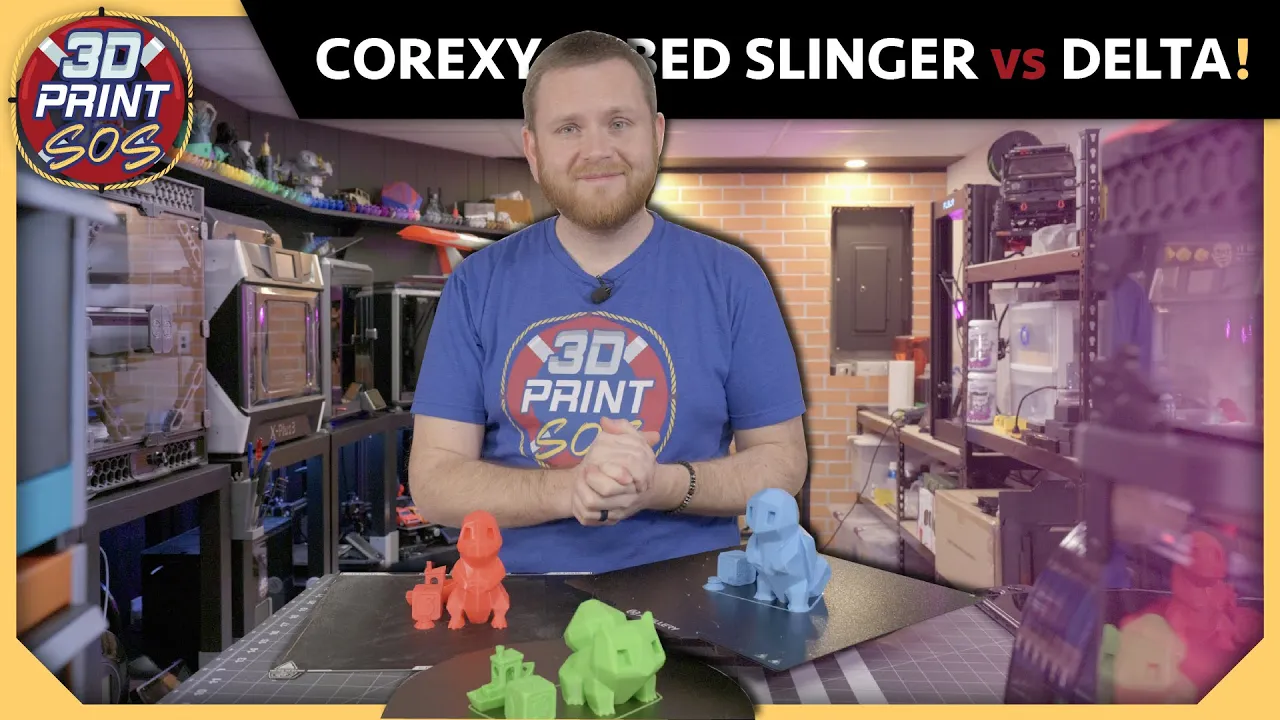
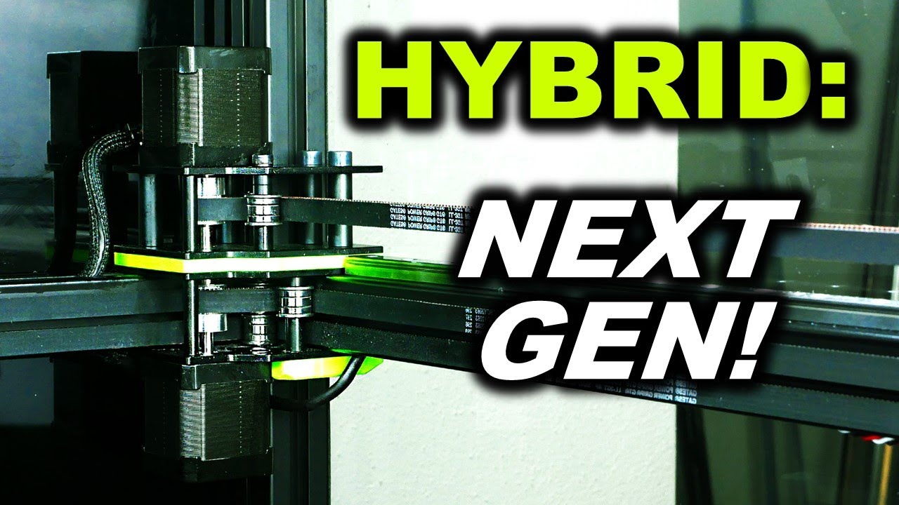
Advanced kinematics for 3D printers, including CoreXY, Delta, and Scara motion systems.
The integration of alternative linear motion technologies such as ball screws, rack-and-pinion systems, and linear motors.
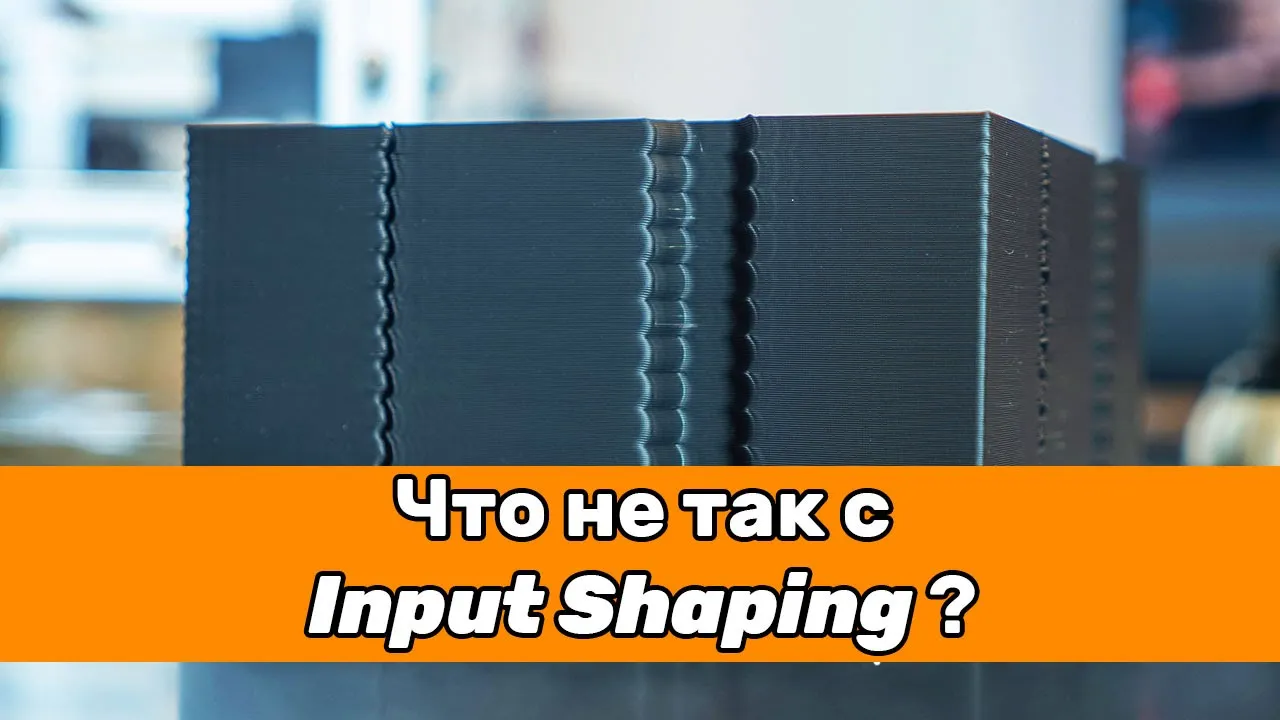
Dynamic vibration analysis and software mitigation techniques, such as Input Shaping in Klipper firmware.
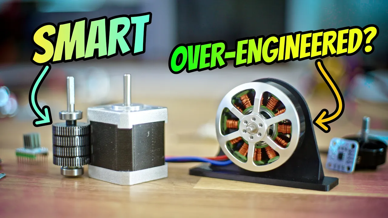
Closed-loop control systems using rotary or linear encoders to detect and correct step loss and motion errors.
162.7K views2.3Klikes35:00Original Release: 2017-09-13
hi welcome to the breadboard in my previous video introducing motion control and the build of my 3d printers that we're going to go through over the next few months I talked about using lead screws for driving all of the axes and quite a few comments came back to me trying to state that lead screws would not be as good as belts because they wouldn't be able to drive at the same speed they wouldn't be able to produce the same kind of talk the motors would have issues and all sorts of things like that so what I want to do in this video is go through some of the differences between using a lead screw or even just a simple threaded rod and using a belt we'll look at the teeth gear that's used for the belt as well as the pitch of the lead screw or threaded rod and see if we can figure out a little using a little bit of math how fast they can go and also whether you would be losing torque or not and what kind of precision you should be able to get not factoring in of course a little bit of backlash although we will try and look at that if we can so let's go and have a closer look at the two things that I'm talking about and get into the details so here we are at the bench with an insulted set of parts that are going to be used for various motion control projects and the items that we're talking about things like this which is a lead screw this is an eight millimeter full start lead screw we'll talk about that when we get to the computer and we can bring up some more detail pictures what you have on one end is a coupler which is used to fasten to a motor so when the motor turns this is a stepper motor NEMA 17 in this case it would rotate the rod as well in the rotation of the rod it would slide this brass coupling in this case along or back on the rod at a certain speed depending on the rotational speed of the motor now the other kind is using a belt which is something like this this is a GT rebelled and what that means is the pitch of the teeth I don't know if you can see that very well I'll put a picture up anyway but the picture of these teeth is three millimeters so if you had something like what I have here which is a 22 year so what you would do is you would normally this is for a bigger motor but nevertheless you would mount it on your motor and then one revolution of the motor would produce an equivalent pulling of yeah pulling of the belt around the teeth and introduce linear motion again on whatever you're driving so whether it be rotational on a lead screw to produce linear motion by threading this knot up and down and that same thing applies if you're using a threaded rod or whether you're using a motor with a gear and you're using a belt the net result is you're converting a rotational motion into a linear motion now the number of teeth or the number of threads and starts and pitch of a lead screw will result in a certain speed based on the speed that you're driving the motor also depending on the gear ratios and things you would also get a talked increase or decrease depending on whether you're driving the load faster for an equivalent speed of the motor or slower for the equivalent speed of the motor and we'll look into some of those examples in a moment as well when we get on the computer anyway I think that's enough on the bench there's not really much else I can show you here except that you know things like the gt3 bell just wraps around here so one rotation of the pulley would result in 20 teeth are effectively rotating around a single point so let's get to the computer and we will see what this all means as far as speeds and talks and stuff like that okay so now for some details of stopping with the eight-millimeter leadscrew here is a typical specification and it happens to match the one that I have so we have an eight millimeter lead screw with an eight millimeter lead with a two millimeter pitch now what this means with the lead screw is an example down here is the difference between a standard threaded rod and a lead screw is just the angle of the pitch and when you have multiple starts it means you effectively have two or three or four or even a single depending if you've got a fine leads for separate threads running down the rod now the pitch is irrespective of how many starts you have or how many threads are running down it is the distance between them so in this case it's the green item here so you can see that even with a single start double start a triple star and a full start they're all the same pitch which is two millimeters what is differing is the lead so in this first one the pitch and the lead is the same the second one the lead is a bit more than the third triple start is a bit more on the four start is even more so what we have is a two millimeter pitch with an eight millimeter lead and what that means then is with one rotation of the shaft you get to move eight millimeters in distance now if you consider that a standard stepper motor is 200 steps per revolution then eight millimeters divided by 200 let's just say eight divided by 200 woops because I kind of did that wrong is point zero full millimeters per step and that doesn't account for microstepping that's just full-blown 200 steps and obviously if you're using a point nine degree stepper motor then that's going to be two tenths of a millimeter moved per step of the stepper motor and if you're using ten or sixteen micro steps then obviously that's going to now be point zero zero two point zero zero four millimeters per step of the stepper motor so that's pretty good let's just continue with this now what we have here are a number of different nut types that can also go on here so this is the typical lead screw he was showing a doll Rijn not applied to a lead screw and what it is is basically a special kind of plastic and this one actually has an anti backlash capability built-in you adjust this little grub screw here and what it does is it tightens up the threads so that there is no play and you just tweak it just enough so that you take up all the slack but without binding it this next one here which is brass it's fairly accurately machined but it does have a tiny amount of backlash on it and we'll have a look at and see that on future videos this variety here that you can see actually has a fairly strong spring between one threaded piece which is the same as this and then a second threaded piece which is you squished it up together thread it onto the rod and then what happens is this second piece actually takes up any slack in this now obviously if you do a high acceleration apply a lot of talk it is possible that the spring could compress and you would get temporarily a slight bit of lag in the movement but typically for most applications this is sufficient so certainly for light load to take up a lot of the slack if you want to stay with metal now if you want to go to something more precise of course you have to go to something like a ball screw where you have ball bearings and things in here now the principle of how far traveled and all that kind of stuff and the losses are pretty much the same there are losses because of friction with one of these and if you're using a threaded rod there's going to be more friction we'll get to that in a moment if you're using a ball screw because there are ball bearings then there's going to be a lot less friction but as far as you know ignoring the losses due to that the gearing ratio is going to be what drives the Mayton the main talk of the motor say it's 40 Newton centimeters if you're gearing then that can change it to be a lot more torque so a lot more load that could be moved but at the expense of moving it slower or depending on how you're doing it you know if you're gearing up then you can have a lot less torque or moving power but you could do it a lot faster and we'll get to that in other videos and we start talking about the motors as well in here we're just looking at how quickly can we move the load per rotation of the stepper motor now we haven't get to the super motor yet we're just looking at the effectively the gearing so we've got one rotation of the motor in this case is giving us a eight millimeter distance move so therefore a 0.04 millimeter step if you want to know what that is in inches that's one thousandths of an inch so 0.0015 of an inch is what is moved there okay so you get a better one foul a lead screw and here's an end view of it you can see the full separate starts on this one now that's what I'm using on my 3d printer alright so considering that we're using a point four millimeter a head like the nozzle on the 3d printer that means that our positional accuracy is worst case ten times better than the thickness of the what we're trying to print and if you include microstepping then it could be as much as a hundred times better than what we're trying to print so more than adequate for the accuracy now we're not considering backlash yet but as far as direct resolution we've got more than enough so now let's go look at a threaded rod a little bit less data here a little bit less complicated typically a threaded rod one of the ones that's commonly used is an m8 threaded rod you'll buy it a stainless steel or something because it's going to have a little bit less friction and the pitch is typically 1.25 millimeters so if you do the math on that one then you will get 1.25 is how far you will move in one revolution so if we divide that by 200 steps we get 0.006 millimetres first step now obviously if you're using a 0.9 degree second motor then there's going to be half that and one of the downsides of this though is you know motives have to move pretty darn quick to get the equivalent speed because you're moving 1/8 of the distance per revolution what it will give you is technically a lot more torque now because of the nature of this basically steel on steel even a little bit of lubrication this is going to have a lot more friction but these brass fittings they're going to give you I think less friction but assuming even if the friction of the same we're moving 8 millimeters per rotation here we're moving 1.25 millimeters rotation on here now these eight millimeter threaded rods they're not designed for motion control they're designed for basically bolting things together so they're not going to be as precision that may not be quite as straight they're certainly not normally ground or anything like that but they will work at a pinch if you want if you've really got to keep it costs down now if we look at these side by side on the Left we have a four start lead screw and on the right we have the eight millimeter m8 threaded rod and you can see there's quite a difference here in the pitch and the quality of the finish and things like that so because of this increased finer finish it's gonna have less friction if it was made the same way as this it will be a little different the other part that's different here is that this has a triple trip this has a trapeze idle profile to it to help in the movement a threaded rod doesn't it's got small square edges and it's actually designed to clamp and bind when you do the nut up it's not designed for free motion if you like so there's you know there's these reasons why even though it's slightly more expensive to go to a lead screw and as you can see up here the resolution that you get is still more than enough for 3d printing or something like that when you're talking about a point four millimeter nozzle right it's still way more than enough when you start looking at a threaded rod you know you you're basically wasting resolution because you're never going to be even even for the vertical z-axis you know you do point two millimeter Leia Heights even point one millimeter and you've got almost off yeah 20 20 times more resolution than you actually need here so you're just wasting resolution now looking at a belt type of system okay this is the kind that I currently have a lot of people will use gt2 s because they have a two millimeter pitch versus a three millimeter pitch now what you also will typically use with something like this and I don't if I have a picture one here is a a gear on the motor with a 22 in it all the way around so what you would have is you would have the belt wrapping around the pulley that's attached to the stepper motor and now what we've got in my case but we'll do the math for both of them is you have a direct relationship on the diameter of this pulley to the rotations of the stepper motor now because I have a gt3 belt that means each tooth is three millimeters if the pulley has 20 teeth all the way around that means that for one rotation of the stepper motor my pulley will move 60 millimeters now if you've got a gt2 it would move 40 millimeters so now and this is typically used for a lot of 3d printers for the X and y direction the Z direction often will use lead screws but the X and y direction very often uses belts so if you've got a 40 millimeter for a gt2 and you divide that by 200 steps that means you're getting point two millimeters that's the best you can do now obviously microstepping is going to give that make that a little bit better well now in accuracies when you're microstepping do creep in microstepping isn't all it's cracked out to be it helps a lot with smooth running it does give you some level of improved resolution but it is not you know once you go beyond about 10 micro steps you start to lose all accuracy at least you don't gain any extra resolution you can get smoother running but you also start losing torque as well and I'll link in an article from the gecko Drive folks that have got a really good description of how all of this comes into play so for my gt3 belt I will end up with point three millimeters per step so that's not very good full at 3d printer that's not highly accurate it's probably good enough in most cases but you can see why in some you know when you're using a point three millimeter nozzle and you know you're not your accuracy is not even ten times better than your nozzle width and you really would want it to be micro something as I said is going to help but it depends on how good your stepper drivers are and things like that now the next thing is going to be speed so typical 3d printing is measured around about I think 50 to 150 millimeters per second so if we want to figure out what that's going to be based on how fast our motors need to turn then let's just write down a few notes here and we'll figure it out so if we want to have 50 millimeters per second speed and we can move at let's just use the gt3 which is 60 millimeters per revolution then if we want to be able to get 50 millimeters a second we only need to turn our motor at one revolution per second and we're already doing 60 so we actually is you know it's less than one revolution per second now pretty much any stepper motor is going to be capable of doing that if we were at a hundred and fifty millimeters per second then if we're doing 60 millimeters it's simply going to be 150 divided by 60 millimeters per revolution that means we need to point five revolutions per second so 2.5 revolutions per second all right so I think that if that makes sense to you so far we just simplify simplify the notes here so for GT 360 millimeters per revolution if you want to go at the slowest speeds 50 millimeters per second that's less than one revolution for a second and at a hundred and fifty millimeters per second that's only two-and-a-half revolutions per second pretty much any stepper motor is able to get that now the problem when you are running at such a low speed is that you start getting the stepping of the stepper motor starting to show up because you're running so slowly and it's not ideal because that will get reflected in your print now if you're using micro stepping that can smooth things down but it doesn't actually change how quickly or how slowly should I say you are rotating the stepper motor and therefore not getting such a smooth potential finish on your 3d printing now I haven't done any exhaustive testing this is just looking at the math to see what we're getting here now if we're using a lead screw then I think you'll see that the situation changes a little bit so let's just go do the math on that so if we want to go at the same 50 millimeters per second then we have to eight millimeters per revolution so 50 divided by eight means we have to rotate at six point two five revolutions per second and if we want to run at 150 then 150 divided by eight per revolution equals 18.75 so 150 millimeters per second equals they say 18.75 revolutions per second so what are these equate to in rpm well let's just do that one's easy equals 60 two and a half equals 150 rpm and for the eight millimeter lead screw which we've got six point two five times 60 gives us 375 rpm and 150 equals is 1125 in this case we're getting fairly close to what might be the limit of some stepper motors up at about a thousand rpm but considering most 3d printers that we're building we're not building a high-end 3d printer here we're building one that is going to be pretty accurate and if you think about a lot of them don't even run at 50 millimeters per second how fast your 3d printer is going to be able to actually run is going to be dependent on how good your hot-end is whether you're moving your built plate or whether it's just the head that's moving obviously if you're moving your build plate and you're trying to move it very fast and stop and starting it over time if you've got a tall thing that you're trying to print you run the risk of dislodging it so you may have to slow things down now if your build plate is big and fairly heavy then you know in the situation where you're using a belt you are having to apply that torque the maximum talk that the stepper motor is able to apply directly to the moving of the build plate so if this is a forty Newton centimeter holding talk I can't remember how exactly that relates to the moving capability there is no gearing between that and the move of the build surface in the build plate with the heater and everything else that's on that and maybe we should do a weigh in on how how much weight a built plate is that's about 300 by 300 when you're using the eight millimeter lead screw because it's effectively being geared down so you know you can see here one revolution of this is directly translating into 60 rpm 60 millimetres of movement one revolution of the lead screw is only resulting in eight millimeters of the lead screw so what's happening is you're getting a talk multiplication here right assuming this direct drive let's just call that a factor of 1 then with the lead screw you're getting 60 divided by eight so seven and a half times the torque for the same speed so if you've got a heavy build plate you're going to be able to accelerate it because you're allowing the stepper motor to go much much faster quite well without stalling the stepper motor if you have a heavy build plate because it's big and you're doing direct belt drive if you try and accelerate up to the 50 or 150 millimeters per second you may find that you're stalling out your motors because you really don't have many rpms to do anything with before you're at the speed that you're going to be able to print to whereas with the eight millimeter lead screw or you know even better would be the threaded rod but of course there's issues with that you know and you don't really want to get ridiculous on how many rpms you can see here with the eight millimeter lead we're already at you know 1,000 rpm for the faster print speed so if you using a 1.25 millimeter so let's just say that's you know five times faster Europe at five six thousand rpm and a lot of stuff and motors won't be able to do that certainly not accelerate to it very quickly I'm gonna say very quickly I'm talking about you know within a few milliseconds with the massive the load and everything else it just wouldn't be possible but by using the lead screw or you know if you really want to go more accurate a ball screw then you have a much better chance of being able to move those bigger masses without stretching belts and various other things so if we go and look at one of the designs and the first one that we're building on that I'm building is basically this one I haven't finished laying everything out yet but I've already covered the video where we looked at this base build and here's our plates you got this big piece of plywood and then on top of that you're gonna have an aluminum three millimeter thick build plate with the heater on it and then you're gonna have whatever you're actually building as well I'm using an 8 millimeter rod lead screw here and then these are just stainless steel polished rods for the bearings to move along to keep everything stable and smooth so in the z-axis these are going to be eight millimeter lead screws as well to raise them low and now gravity is going to keep this down so backlash is not so much an issue in the z-axis and then in the x-axis here the only thing we're moving is this fairly lightweight piece with the head on it I don't plan to have the extruder itself mounted on here I'm going to use a Bowden tube so that will be mounted up here somewhere so very minimal mass but the mass of this to actually accelerate if you were using a belt your acceleration would have to be relatively slow to avoid slipping on the steps of the stepper motor I would imagine or you'd have to crank up and increase the current and increase the voltage that you're using on your stepper motors obviously the amount of power that you instantaneously apply to these stepper motors controls how much toque you're going to get so a lot of proves or I three clones and things like that use a 12 volt system what I'm planning on using is a 24 volt system a lot of my other motion control systems you can go up as as a 48 volt even though ii motors themselves are basically the same it is because of the inductance of the motors and things like that that by using a higher voltage for the supply and using a quality stepper motor driver you can actually get a lot more low-end torque out of these so that you can do your acceleration now obviously once you're up to higher speeds you don't get the same amount of talk but you don't need it once you're at that speed you just need to be able to maintain the momentum and then slow down again and a lot of the tuning parameters of your 3d printer is one is going to control how quickly you accelerate and decelerate and how long you can remain at high speed now again as I said a lot of the issues that reduces how fast a stepper motor or 3d printer can run not actually directly related to the stepper motor itself the hot and how quickly can it heat the filament as it goes through to maintain those higher print speeds how quickly can you push it the stepper motor that is driving the filament through if you try to drive that too quickly you may end up just stripping chunks out of the filament instead of driving it through to the hot end you know so a lot of factors come into play when you start increasing the speeds so you know if you're still playing around in the 50 to 100 millimeters per second even there 150 millimeters a second you're still easily able to do that with an eight millimeter lead screw now as I said with the belt when you're trying to do this you're running it a lot lower speed in your rpms and that can easily be done but that can also introduce artifacts from the steps because the stepper motor potentially at these lower speeds for instance will stop during its movement it'll kick because you you apply the next pulse for the stepper motor to move to its next position but then it holds it for a second it's not like a DC motor where it's a linear progression all the way through the net result of the RPM would be say 60 rpm and the speed would be 50 millimeters a second on average but between each step it's going to be trying to go as quickly as it can to lock into that next step position so you can actually get some artifacts showing up at the lower speeds if you're not running your stuff Moto's fast enough and again as I said I'll link in some articles from gecko that covers these kind of things now the only other issue really of using a lead screw which I've actually alluded to in my first video is the fact that there is a little bit of backlash with the nuts that I'm currently using but I intend to actually see if I can get some I guess bearings with I guess rods to do my 3d printer and in this case there should be a lot less backlash but it can also get some anti-back brass inserts like I've already shown you up here where is it that these these type of things so if we do get too much backlash then we can apply one of these and that should improve things now again it depends on how quickly you try to accelerate and things like that when you go to something like a core XY of course you really don't have too much choice about using threaded rods or belts but you do have a minimum a two to one gearing ratio when you're using a core XY which means that you are running at twice the speed of what we calculated down here for the belt so instead of 60 or 120 and 300 rpm for the same speeds and if you had long enough belts you could even improve upon that now obviously backlash is dependent on how you have your belts and the longer the belt the more stretch that may be within that belt as well it's not a lot but it's always going to be there and you know once we start building a belt based system we will see if we can measure that somehow to show you but for now I think what I wanted to show you in this video was really what the difference is and why a threaded rod or sorry more specifically elites group is a very viable option for using in all of your axes on a 3d printer because the stepper motors can get the highest speeds especially if you use higher quality ones and Irish components that has been kind enough to send me a bunch of stepper motors and these are point nine degrees Stefan motors so I'm not sure which one of the two machines I'm going to use them in I'm probably gonna use them in the core X Y but I also have a set of one point eight degrees stepper motors as well and some fairly good stepper driver using an SD micro controller board which we will try with this that should be able to give us some good control of the motors and we will see how well in reality it is it might be slightly noisier because it's metal shaft rods versus belts but I think the higher rpm it may actually be quieter on the motors versus the other mechanical parts anyway that's it for now I didn't want to make this too long and it's already about half an hour just over half an hour long I think that's about it so if you got anything good out of the video just give me a thumbs up if you didn't then don't but I'll see you in the next video when we start building a bit more of the 3d printer thank you you
Up Next
8:02
CNC Shield Arduino UNO DRV8825: Setup Tips for Reliable Operation
@jtechcustoms
159.2K views•2020-02-27

30:32
Ultrasonic Transducers: Resonant Frequency Measurement and Horn Design
@imajeenyus42
229.9K views•2017-02-22

54:16
Polymer Environmental Degradation: Mechanisms & Stabilization
@iit
1.8K views•2012-07-10

33:39
How a Student's Question Saved a NYC Skyscraper from Collapse
@veritasium
22.8M views•2025-04-26
Related Study Plans & Knowledge Roadmaps
Structured learning paths in Engineering
engineering
Building Acoustic Levitators: Physics & Arduino
01The Physics of Sound and Standing Waves
02Piezoelectric Transducers and H-Bridge Drivers
03Arduino Programming: Generating 40 kHz Signals
+ 2 more learning modules
14h5 modules
Explore Roadmap
engineering
Building Peltier Cloud Chambers: Particle Tracks
01Cosmic Rays & Cloud Chamber Physics
02Thermoelectric Cooling (TEC) Fundamentals
03Custom Liquid-Cooling Loop Design
+ 2 more learning modules
18h5 modules
Explore Roadmap
engineering
Yagi-Uda Antennas: Modeling, Build & VNA Test
01Introduction to RF and Antenna Fundamentals
02Yagi-Uda Antenna Design Principles
03Antenna Modeling and Simulation in 4NEC2
+ 2 more learning modules
18h5 modules
Explore Roadmap
engineering
ECG Monitor Design: Op-Amps, Filters & Noise
01Electronics & Breadboard Basics
02Op-Amps and Instrumentation Amplifiers
03Bioelectricity and ECG Fundamentals
+ 2 more learning modules
18h5 modules
Explore Roadmap