














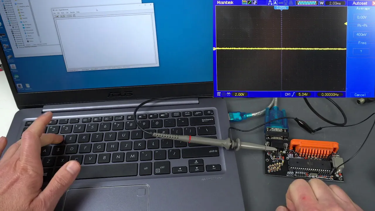
This video tutorial demonstrates how to set up and operate Universal G-Code Sender with CNC milling machines, covering essential steps including connecting to GRBL firmware via COM port at 115200 baud rate, performing machine homing using $H command, configuring work coordinate offsets (G54-G59) through G10 commands, utilizing keyboard jogging controls, and executing G-code files safely using check mode verification before actual machining.
UGS Setup Guide for CNC Milling Machines: G-Code Sender Tutorial
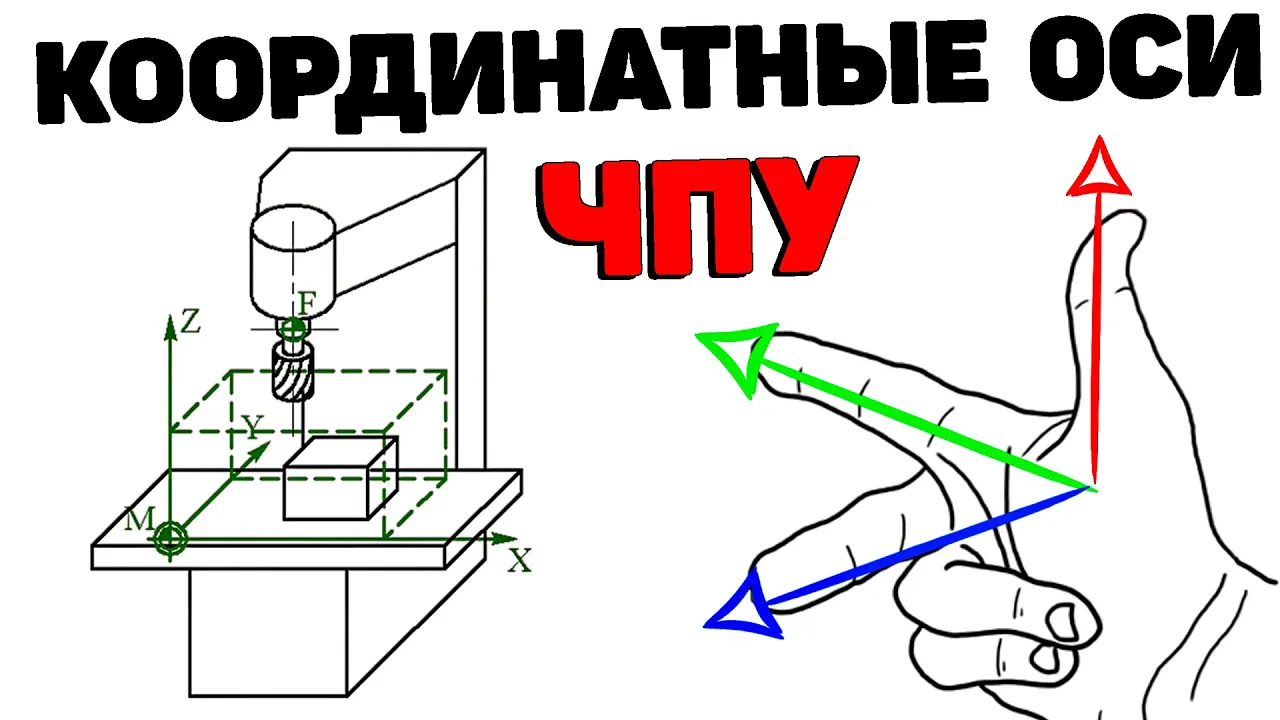
Added:Basic understanding of the Cartesian coordinate system (X, Y, and Z axes) as applied to CNC machine movement.
Familiarity with foundational G-code commands and syntax, such as rapid positioning (G0) and linear interpolation (G1).
An understanding of CNC machine anatomy, specifically the relationship between the machine controller firmware (e.g., GRBL) and the sender software.
The conceptual difference between the Machine Coordinate System (absolute physical limits) and the Work Coordinate System (temporary part origin).
Writing and implementing custom UGS macros to automate tasks like auto-tool zeroing and automated touch plate probing.
Configuring CAM (Computer-Aided Manufacturing) software post-processors to ensure generated G-code is fully compatible with UGS and your machine's controller.
Advanced workholding strategies using multiple coordinate system offsets (G54 through G59) for multi-part or multi-fixture setups.
Troubleshooting serial communication issues, baud rate mismatches, and electrical noise interference between the host computer and the CNC controller.
25.2K views170likes13:12Original Release: 2016-05-08
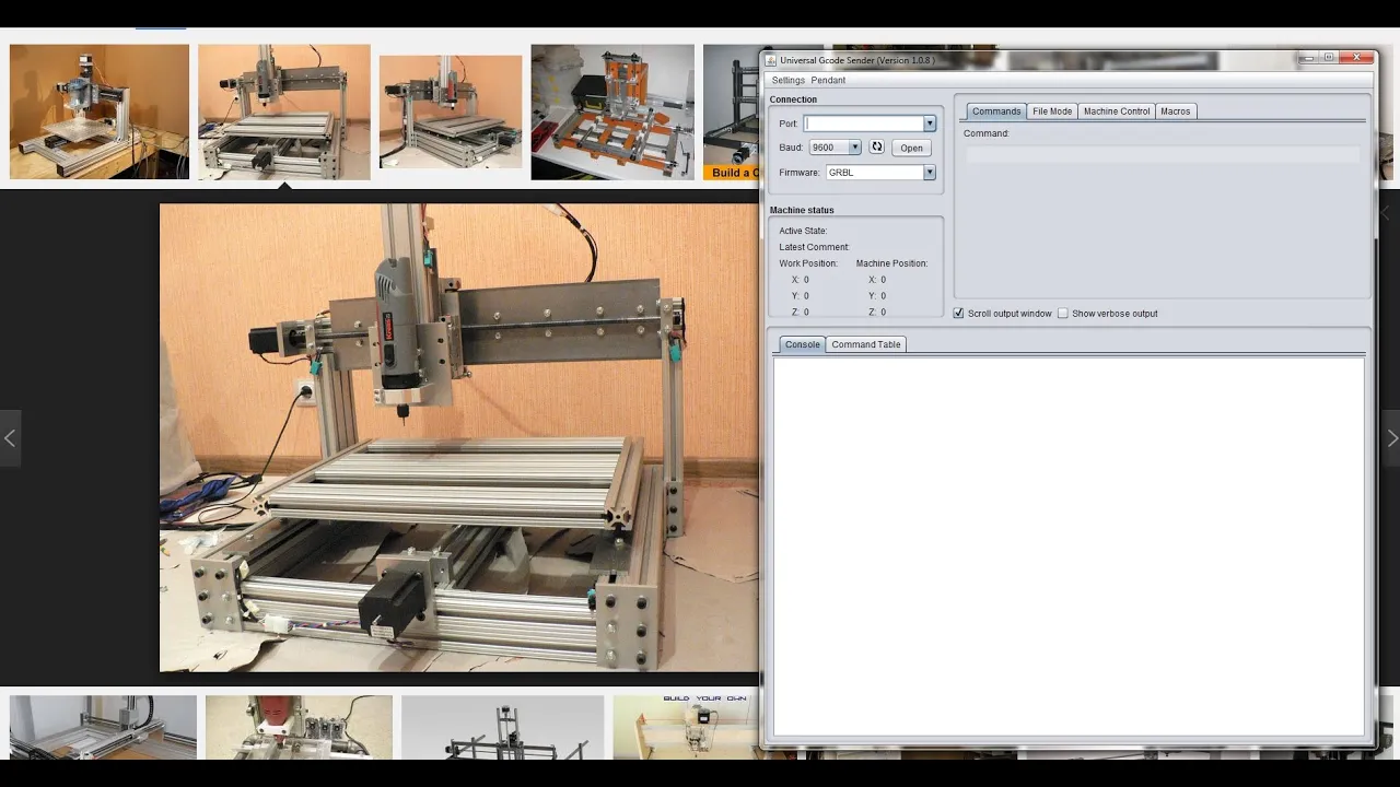
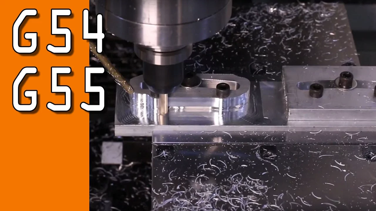
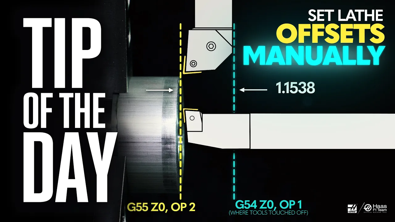
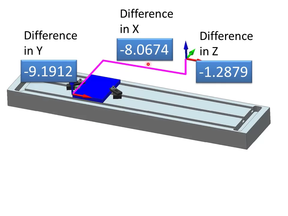
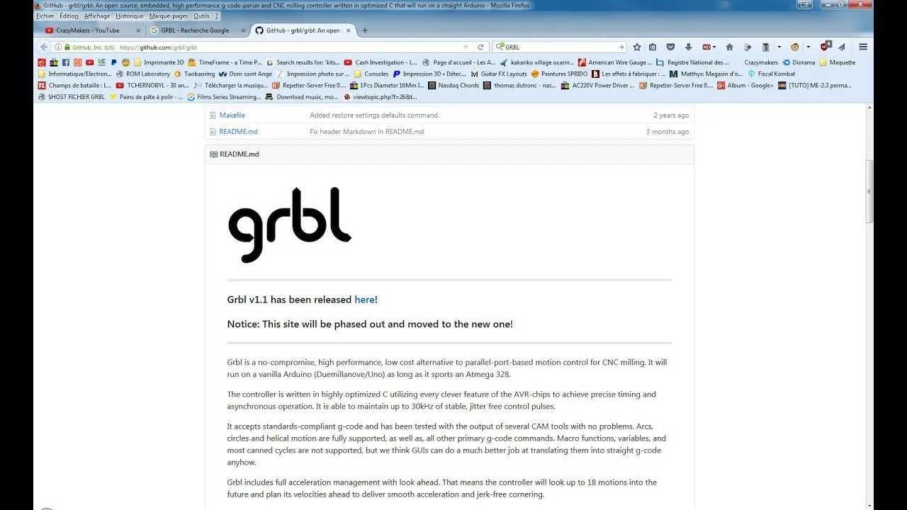
hey everybody this is Larry from Leading Edge Industrial Technologies and today we're going to go over using the universal G-Code sender and how to set it up with our machines so the very first thing you'll do when you launch Universal G-Code sender you're not going to see this little video window here that I've got in the in the picture I can't click on that right now but uh what you'll see is the um uh the universal G-Code Center the reason why I've got the window here is because there's going to be can doing some movements with the machine and I want you to be able to see that so um as we go through some of the settings here I want you to be able to see what we're doing the very thing first thing you're going to notice when you set up the uh Universal G-Code Center you start it up is your comp Port will be listed over here uh I always tend to hit the refresh button because every once in a while it'll it'll assign a new comp port and uh um you'll need to connect to that so by hitting the refresh button it'll grab the latest one and uh from there you can go ahead and select open uh again when we go ahead and open this up with our machine you you want to have 115200 B on there and make sure you set set it to garble as the operating system or the firmware um over here to the right you're going to see that you have a command level or a command screen and uh right there you can do your manual data input just like a a standard CNC machine um you've got file mode for grabbing files and loading those you've got machine control which is kind of like a quick access panel and uh you can use this for jogging around I prefer to use the buttons and uh or the keys on the on the keyboard and we'll go over those and then uh over here you've got macros which I'm actually very excited about this is a new feature in the uh 1.0.0 n or point9 and uh um I actually made four macros right away the first day I saw this because it's exactly what was NE what was needed so the very first thing we're going to have to do when we start up this program is with our machines we have limit switches on here that at the uh most positive Axis or points of each axis so then that way the machine knows what home is so we're going to go ahead and go to machine control and with our machines you do have to home it otherwise you can't do anything you'll see this active State alarm that means basically it's not going to move because it's uh it's in an alarm State and the alarm state is I don't know where I'm at so please home me so hit dollar sign H and you'll see the machine move and now my machine's home if we look over here at the work position and machine position uh the actual machine position is listed as 059 it's because we're in a 1.5 mm off of the limit switch from the point that we trigger the limit switch that basically uh the machine moves up to the limit switch and then moves past it so then that way you uh you have a bit of a buffer there before it turns off the uh or turns sets the alarm on um one thing I didn't go over when we first connect is when you connect to garble you're going to see this line here connected to com 5 1152 200 bod the next two lines are are going to list the garble version you're using dollar sign for help or dollar sign H dollar sign X to unlock and uh dollar sign H is what we just did which is the Homing dollar sign X is unlocking and allows you kind of free mode in there um with our machine I always recommend you do dollar sign H and home it so let's go to commands here with commands there's a couple of nice things that you can do here we've got um if you do dollar sign dollar sign it'll bring up all of the machine parameters and each one of these are changeable so the way to change them is to let's say we wanted to change um let's see here let's let's say we wanted to change our our millimeters the amount of area that we pull off the uh the limit switch so right now it's 059 in the machine position which is 1.5 mm so if I type uh dollar sign 27 equals let's make it three it'll tell me okay so you'll see okay down here and then uh if I do refresh which is dollar sign dollar sign it'll bring up all the new commands all the latest parameters you'll see dollar sign 27 changed to 3 millimet now when I go back to machine control and I hit dollar sign H for home you'll see here it'll move 118 which is 3 millim off the um limit switches so I'm going to go ahead and change that back dollar sign 27 equals 1.5 hit enter and then I'm going to go back and home it again and then there you go there's your first parameter that you changed all the other parameters are changeable and I'm not going to go over each individual one of those um what you're going to have to do is get online and uh and if you just do a Google search on grbl um it'll bring up all of the parameters and uh what those stand for and how to do it um maybe some other time we'll go through each one of the individual settings but for now use the default settings on your machines until you get comfortable with it then go ahead and visit the uh the garble page so now we're going to go over here we're going to stay in the machine control over here and uh first thing we're going to do is we're going to hit help help goes over a lot of the things here they're kind of self-explanatory so I don't have to read this to you what I highly recommend is that you go ahead and pop open the help and try out each one of these little features um it uh it's imperative that you know and get familiar with this software uh jogging it around and doing that the only way really to do it is not to have me tell you how to do it is to get in there and and start messing around with keyboard enabled which is right over here um with that off you can uh hit the left and right arrow keys and nothing happens but as soon as you click it now if I uh click the right arrow or the left Arrow key my Mill moves you can see it moving it's moving 0.1 in 100,000 each time and uh I bring it down same thing so and if you see if you go to the help menu it says uh you can increase and decrease the steps I like to leave my steps in uh whole numbers like uh 1.1 01 001 because that's the way my I was always taught how to use a a a larger CNC machine so with mine uh if you go with the increase decrease it's um I I use Control Plus we'll move increase that by uh one/ tenth of whatever you had before so now if I move it left or right it moves an inch at a time one word of caution I would say stay away from the reset buttons anything that says reset zero X Y or Z stay away from those because that's actually a g92 offset and it kind of messes with things if you're just going to do a quick program and need to do something you know maybe you could jump in and use that like make a quick part or something like that but really it's worth your while to go in and do the g54 offsets because you can call them back either g54 G55 G56 g57 you know through 59 you can use those um and I highly recommended using those versus doing the reset zero and uh The Return To Zero brings it all the way back there as well for these these axes uh the next thing is we're going to go over is um when you when you draw an error It'll ask you to do a reset so when you draw an error such as uh the emergency stop switch or you exceeded the soft limit or something like that you're going to have to do a soft reset you'll hit the soft reset button and then you'll hit the X for alarm and with our machine we're just going to go ahead and home it [Music] there we go now we're homeed you can see we're off 1.5 millim off of The Edge or 059 in uh I work in inches and half for 20 years and that's uh uh just the way that that we roll here so um now that's moved off now what I'm going to do is I'm going to move to an an arbitrary plane here I'm going to show you how to um set your uh g54 using the macros uh Again by going to garble um looking up garble g-codes it'll bring you to shape oo which has all of the g-codes in there garble and J shape oo they use about the same software they they're just variations of it uh and what it does is there's a a G10 G10 is um it's explained in those g-codes but to kind of quickly go over it G10 is I want to set an offset P1 is your g54 and then you could go up to I believe it's P5 and that would be g59 and uh then l20 means that I want to set my current position to whatever I tell it so I could say x.125 uh you know and it would say that that's what it is so say you're doing like a touch off on the side which we're going to go over in one of our videos here coming up real quickly is how to set the the X Y and zero Z points um for doing a machine part so right now since we're going to uh we're at home I'm going to jog down just to a random position okay now just for for grins I'm just going to call this this is what I want x y and z0 so X Y z0 you can see I created these macros here it makes it really easy instead of having to go back to the commands menu and type in G10 P1 l20 x0 just go ahead and set that as a macro and down here g43.109 to that last position so we'll let it home here it'll finish homing and uh you can see it defaults to our g54 which is our first fixture offset it's got the XY plane inches um absolute coordinates and it mode is in uh inches per minute that's your feed rates uh we've got a couple other settings here that we're not going to go over because they really don't pertain to anything right now and uh but for now just as long as you understand what these g-codes and uh uh we'll get moving on it so the first thing I'm going to do is since we're already in g54 mode I'm just going to say rapid 2 by going to a g0 0 I want to say x0 y0 z0 and when I hit enter it'll rap it to that g54 corn here we go so that's pretty cool it's kind of the gist of things here you can go up to file mode and when you have an NC file you just click browse and you look for an NC file NC or um I don't know I don't remember where I set box up at so um what we'll do is we save that for another program so I can go ahead and set the uh the zero points exactly where it needs to be but uh you just grab your file here say open once it opens and you uh and you're ready to go click Send and it'll send the file up and you're ready to go now there may be some files you know as you're doing postprocessor um upgrades or uh editing your post-processor output you may want to test the G-Code without running the actual machine just in case it causes a crash or um you know errors out on an alarm so what you'll do is come up here to the uh dollar sign C and you hit dollar sign C and by clicking here it'll tell you it's check mode so this basically runs your entire program and it will let you know if any errors pull up here if you exceed soft limits all of that stuff it just pulls right up then once the program's done you'll hit dollar sign C again and it'll put you right back to where you were in your mode as if it HED again and it still knows where we are down here so I think that's kind of the gist of everything here um uh it's a quick video but I just wanted to go over it really really fast uh and we'll slowly build into projects that are um using Universal G-Code sender and how to set up our machine so please click like and uh and subscribe below so you can see new videos as they come out and uh I hope to hear from you in the comment section below thanks bye
Up Next

12:03
G-code Tools Tutorial Part 1: Inkscape Setup and Engraving
@MatthewSmith-wh5dr
84.5K views•2012-05-23

12:54
Triumph of Orthodoxy Icon: Byzantine Art & History Explained
@BenCallan
2.1K views•2024-08-06

9:49
FastAPI vs Flask vs Django: Choosing the Right Python Web Framework
@TechWithTim
302.5K views•2024-05-26

1:42
Game of Thrones Opening Credits: A Cinematic Analysis
@gameofthrones
46.3M views•2011-04-18
Related Study Plans & Knowledge Roadmaps
Structured learning paths in General & Interdisciplinary Studies
general-studies
Elevator Engineering: History, Physics & Cities
01From Hoists to Safety Brakes: The Dawn of Vertical Lift
02Hydraulic vs. Traction: The Engineering Physics of Elevators
03Modern Speed, Safety, and Algorithms
+ 2 more learning modules
12h5 modules
Explore Roadmap
general-studies
Rubber: Material Science, History & Geopolitics
01Origins of Natural Rubber & Mesoamerican History
02The Chemistry of Natural Rubber & Vulcanization
03The Geopolitics of the Rubber Boom & Colonization
+ 2 more learning modules
12h5 modules
Explore Roadmap
general-studies
Containerization: Evolution, Logistics & Trade
01Ancient Trade & Bulk Cargo: Amphorae to Barrels
02The Industrial Revolution & Cardboard Packaging
03The Containerization Revolution: Malcom McLean
+ 2 more learning modules
12h5 modules
Explore Roadmap
general-studies
Textile Tech: Evolution, Labor & Global Impact
01Pre-Industrial Textiles: Handloom & Cottage Industry
02Mechanization: The Spinning Jenny to the Power Loom
03The Factory System & Global Labor Transformation
+ 2 more learning modules
10h5 modules
Explore Roadmap