

















![[BCMH-TTĐK ROBOT] Xây dựng và điều khiển Robot SCARA 3 bậc tự do](https://i.ytimg.com/vi/-mJS9ncU6vY/maxresdefault.jpg)



Cable-driven parallel robots offer a promising solution for additive construction by providing larger workspace, easier transportability, and cost-effectiveness compared to traditional serial or gantry robots. This technology enables automated concrete printing for building construction, addressing the limitations of conventional construction methods which are slow, waste-prone, costly, and hazardous to labor. The key challenges include solving the multiplicity of solutions in over-constrained systems through optimization criteria (minimizing tension, minimizing deviation from mean tension, or maximizing tension), accounting for cable mass and elasticity in dynamic modeling, and designing reconfigurable systems that can adapt to changing construction requirements. The comprehensive dynamic model must consider cable stiffness, damping, and flexural properties to achieve accurate trajectory control during the printing process.
Cable-Driven Parallel Robot for Additive Construction | IIT Roorkee Talk
Added:welcome to like uh like our seminar series and uh also like everyone online also will come as well so we are glad to have today we have a professor partak from uh Indian Institute technology nuclear and he's waiting us for this weekend coming next week part of it and he's he will give a presentation today do the lecture on like robotic construction and the professor Professor Patrick his research areas in robotics Dynamics under control as well as a farm graph modeling and he's a professor in the mechanical an industry engineering department at IIT rookie since 2006.
he has been working in on my microtronic for a long time and he has called her book on intelligent microphobic systems modeling control and diagnosis published by Springer in year 2012.
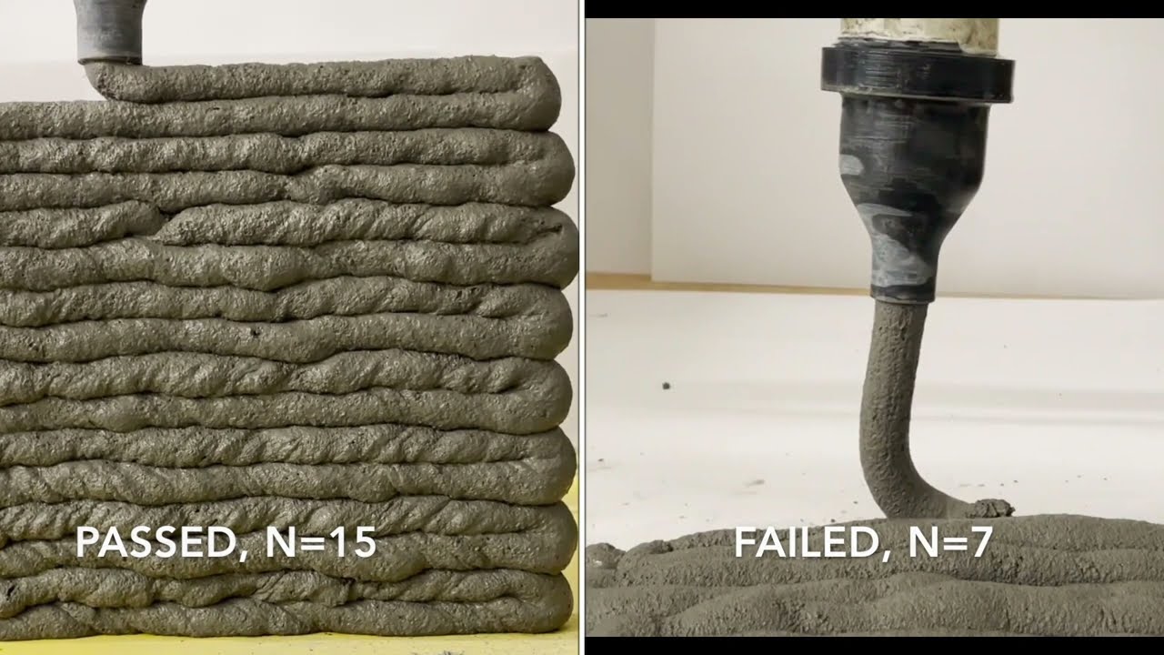
he also has like several online like courses through National program on technology advanced learning on microtronics and modeling and simulation of Dynamics systems and these two courses has been very popular he's a founder of a startup Global Life private like limited with a startup company this company Works to take your body's products developed in the robot's lab to the market he's a member of Esme and I have a packed committee for multi-body Dynamics so here welcome Professor padak to give you the talk today and please go ahead yeah thank you personally for nice introduction it's my pleasure to be here among all of you it's almost vacation time going to be there so yeah so initially I'll just talk about uh my Institute I that is IIT roorkee then uh about my lab which I am heading Robotics and control lab and finally uh my presentation of the day which is based on our collaboration with uh prasurala and Professor Lee through spark project which is about to end I by 31st of March this year so it's almost because although the project was of in ah initially two years but because of Kuwait it has been given twice extension and ultimately it will be winding up on 31st March so uh Indian Institute of Technology uh these are autonomous institutions governed by government of India Public funded institution there are many numbers almost 22 in numbers uh many of them has been recently established but ours has been the initial ones ah of the iits so uh IIT roorkee was established not as an IIT rather Thompson College of Engineering by britishers when India was under colonial rule 175 years ago and it is oldest engineering College in India one of the Institute of national importance and its dream academic destination among the students ah originally established in 1847 as Thompson College of Engineering and later on it was given the status of University after we got independence and in 2001 it was given the status of Indian Institute of Technology so we have 23 departments three Center of Excellence one school 520 plus faculty members 9500 plus students out of which 50 percent are undergraded 25 percent post graduate and 25 5 PhD students our campus is fully residential for a student as well as faculty and we have two Satellite campuses one is in Noida which is uh in the national capital region of Delhi and another one is nearby to root k so uh uh coming to our Global collaboration and student scholar Mobility ah 100 plus countries from where a student have been educated 250 plus International students are studying presently there are 100 plus mous with foreign universities and in fact with Queen's University our Institute has recently signed the Mio I think few weeks before there are 560 plus research and consultancy project 470 plus global agencies and clients 148 plus sponsored research projects and 250 plus patents files and granted ah we had a global collaboration Footprints uh The Institute motorist collaboration not competition so uh this is a ranking uh as per uh the different ranking agencies fifth in India uh in terms of innovation achievements and then selected twice as row as one of the most Innovative Institute in India by Confederation of Indian Industries then first in architecture in India six ah and seventh overall in the uh nirf ranking which is ranking by government of India and 369th rank in the Qs world ranking so I'll quickly cover these of these things here are some of the Excellence here recently we have a data science and AI Center has been set up seven new academic programs has been Incorporated uh there is a center for drone research which has come up space technology cell has also recently come up and yeah so ah there is an acute focus on uh flow of talent to create Global Knowledge partnership and promote Innovation we have joined dual degree programs with Foreign Institute where uh say for example joint doctor degree program where a few semesters student do their research work in the foreign University and a few semesters they do in IIT roorkee and the degree is awarded jointly so one of our such agreement is there with University of Alberta which is going on since last so many years uh dual award degree and Joint Supervision in Project dissertation and thesis this is also uh done we have joint in international projects through various initiatives of government of India ah there is a faculty exchange initiative ah there are various programs in fact international science and technology Corp cooperation then uh scheme for promotion of academic and research collaboration is spark this is the scheme under which I am visiting here and we have been awarded the project there is other scheme visiting Advanced joint research which they call it as vajra there is global initiative of academic Network Gyan which is essentially conducting of short-term courses with the cooperation with the foreign faculty and there is a scheme with the Asian countries as well we have international Network Duo India Fellowship programs are there DST Africa initiative sastri India Canada Institute it's again Fellowship very popular among the students IC impact then set to president's forum for South Asia and Taiwan universities uh United States India Education Foundation Japan Society for promotion of Science and so many uh visiting faculty at IIT roorkee we appoint foreign faculty for a fixed tenure of up to five years and appointment is being done uh as visiting Professor associate professor or assistant professor and uh it's available up to three years and nominations can be made by head of department or faculty member of The Institute here are some of the Innovation activities which are there in our Institute ah there is a rethink Innovation lab is there then there are technology incubators I have division Park if you have a company out of uh any idea of the student or faculty then there are smart City projects uh there is a param Ganga supercomputer which has been recently established there is a Technology Innovation and development of Entrepreneurship support business incubator which provides funding to the student and faculty so we have a vibrant and vivacious campus live in fact processarily has been part of one of such activity because when he is visited us there was a student cultural program was going on for three four days so we have a very wide there are many Student Activities for such as artificial intelligence and electronic Society model and robotic section and so on yeah so ITR unless still look forward to further strengthen our Global cooperation in the field of research and innovation so ah this is all about IIT roorkee I'll quickly ah just give you a brief about uh our activities ah and then I'll move on to our presentation yeah so ah robotics ah and control lab I am heading that lab since 2006 over there ah we have international collaboration ah with uh many of the institutes across the globe in Asia with cantok National University we had a two three year projects on the hyper redundant robot and the walking robot are then in Europe we have collaboration with France University of Lille and we worked on the mobile Cooperative bionic robot uh in South America we have had collaboration with University of national day Rosario on the hybrid manipulator with Queen's University we are working on design of cable driven parallel robot and we have been recently awarded two more projects with the U.S universities University of California Irwin on UAB for mining application and with all dominant University North locks Virginia on UAB for flawed estimation so our research work ah varied ah we we work on the very topic ah under robotics such as the Space robot quadrupt mobile manipulator uh to name a few we have recently added up topic of construction Robotics and Soft Robotics in our area and we are venturing into machine learning and AI application in robotics so these are some of the earlier work which we have completed ah these are part of the different research projects that is walking robot with compliant legs we developed one and tested here then the wire actuated hybrid there is a robot a hybrid robot for ah bomb detection and Disposal basically ah which was developed by the difference Research Institute and they wanted us to explore the possibility of the wire actuation of the joints because currently they are using the motors and it becomes very heavy ah that is the arm load has increased a lot so they wanted some wire actuation so we worked on that then mobile robot with manipulator this was the project which we did with Argentina there was a Space robot project initially we have been granted then ah one on the miniature robot for endoscopic surgery for biopsy sample collection so this also we were drop on so this is the surgical robot setup which ah we did recently my PhD student completed this one work where we tested the mini nature robot on a chicken artist tissue ah this is the work which we did with the University of LED in the France ah on the bionic manipulator because these are basically the continuous manipulator which have infinite degrees of freedom and accurate Dynamic model can help in the control methods basically so we try to create a dynamic model as accurate as it can be for that purpose ah then this is the work which we are currently doing pneumatically actuated Continuum manipulator ah basically this bionic manipulator is pneumatically actuated so it has got say severe limitation on the payload capability it cannot carry lot of payload so we try to overcome that with the help of a wire actuation of the ah Continuum manipulator so this is another PhD student who was working who is working sorry this is the hyper redundant soft robot this is the work with the South Korean University ah which we are currently doing ah so ah this ah we did the dynamic simulation of that ah and then we tested a prototype where we developed a unique ah pneumatic actuator here ah for the serpentine motion of the board and then we worked on the Drone with the aim of putting that hyper redundant manipulator on the Drone so we did ah modeling Dynamic modeling and simulation of the ah drone here it is H type of quadcopter ah this is another work which was done by one of my PhD student who works in the building research so here we developed a robot prototype for the inspection of high-rise building having both metallic and non-metallic structure so this was uh yeah so for the metallic structure we worked using the magnetic type of adhesion whereas for non metallic we worked on the suction type of adhesion so ah yeah our construction robot activity started with the serial type of manipulator actually ah initially for bricklaying purpose ah so we did initially some work on this and then proposed uh this uh for a high rise building of course not very high rise up to say second or third floor and then this is the work which we are doing with prosely and process cable driven construction robot so the this is what ah weak conceptualized maybe I will talking more about in my lecture and yeah the for this we carried out the simulation and the experimental studies this entire experimental setup was ah prepared in-house in our lab which is ah in a full working condition currently ah this is the work of one of my other PSD student who is working on path planning of omnidirectional mobile platform using Ross navigation Stacks where in the home environment we want to plan for the mobile robot so that it can avoid the static as well as the dynamic obstacle in breaching from one room to another room and this is about the startup we have come up with a contactless medical registration device Tara basically and during pre-covered ah kovit period we worked on it and which has now taken shape of a startup and the recently it is going to be deployed in the hospital in roorkee and it's especially helpful when there are long queues long queues in the hospital so multiple deployment of this device can lead to the ah lesser registration time so with this I complete ah my lab introduction and next up I'll talk about uh the work which we have done on this one that is design and development of cable driven parallel robot for additive construction ah although it's a work of my PhD student which spanned almost five years but I'll just try to give you the glimpse of what we actually did and leading to the experimental development of the experimental board so before I start I would like to acknowledge ishan chawla the PHD student at tirutki who worked on this project in fact he visited Queens for six months also he was here in this campus ah as part of his visit as part of the project processor Lee and my other colleagues process samanthre from IIT kharagpur who was co-principal investigator and Professor UK Sharma who is from the Civil background and he helped us in conceptualization many of the things so ah conventional ah construction ah is basically ah as you know its slow waste prone costly it has got limited architectural freedom and hazardous to labor so a pupil thought of doing some sort of automation into it bringing some sort of automation so ah the came the concept of bricklaying came there is a company in U.S basically so they developed used a Serial manipulator basically for bricklaying purpose and applying of the mortar on the brick so ah it's a time saving can work in hazardous environment can be cost effective there could be some architectural freedom and labor safety is also possible here so ah if we ah think about the possible solution for the ah construction use of Robotics in construction there could be three probabilities one is the serial robot or other is the Gantry one and the third one is the cable driven parallel robot if we look for the serial robot so this is how the serial robot can be used for uh the say printing of a house but uh because it has got a fixed base ah naturally the workspace is going to be smaller and if you want to make the base Mobile then naturally you need a smooth terrain for the mobile to move so mobiles in a robot require proper floor for mobility and again there are issues with how to pass through the doors or the opening which are going to be in the house ah the other solution is the Gantry robot ah but it has got again ah limitation as a limited workspace heavy structure ah it's a basically a type of Cartesian manipulator ah and it required very high torque actuators and of course ah one you you want to shift it from one location to another location there are problems so it is difficult to transport and install the solution which I am going to talk about is the cable driven parallel robot ah it can cater a larger workspace and it's easy to transport because we are using cables easy to disassemble and reassign some reassemble and ah it's a relatively inexpensive so coming to the terminologies of this cable driven parallel robot ah we can see that it essentially has got a mobile platform where we could have the concrete mixture OK ah from where the mixture could be poured into and this mobile platform can be driven by the multiple cables basically ah which are attached to the actuators or that is attached to the motors OK ah so here ah the parallel robot in which cables are used instead of the rigid link that is why we call it as the cable driven parallel robot there are very key features of it and that is the high payload to weight ratio we can carry larger payload over here that is the mobile platform can have a lot of ah concrete mixture into it ah there is a larger workspace ah possible so you can think of building say two bedroom or three bedroom houses ah easy to transport ah easy to assemble and disassemble and relatively uh inexpensive it's not that the concept of cable driven parallel robot is new okay the cable driven pilot robots are there but in the different applications for example in the stadium camera you can see that it zooms from one location to another location then a large scale motion simulators also people have been using it high speed operations and in fact in the telescope also ah it has been used so when we conceptualize this project proposal so this is how we conceptualize this that ah we could have a mobile platform over here which could be hanged through uh through cables which are guided through police and actuated at the end ah with the help of motors and the mixture could be pumped into from the concrete mixture over here and these police could be guided through a frame basically they could be attached on the frame and it could be guided and the house design can be kept as a say solid model or whatever design you want that ah you can keep in the model and then ah yes this design ah the trajectory for this design ah to follow could be generated and yes concrete can be poured here the only limitation ah in this one which we felt was that ah the ah time taken for the curing OK because ah one cannot deposit the concrete of Greater height otherwise it bulges so ah there is a literature on the cable driven parallel robot available uh one could be a configuration of suspended cable driven parallel robot like this suspended through wires so here since it is suspended ah there is no issue of the cable collision with the printed structure but since it is suspended there is low stiffness in the Z Direction vertical Direction then we could have the over constant cable driven parallel robot many times what we do actually is that to make the structure stiffer we provide multiple number of cables ok but when you provide multiple number of cables what happens that we try to make the structure over constraint so the that happens plus since we are using multiple number of cables what problem happens that many times those cable start obstructing the structure which you have already created so again that causes a problem then we could have so a solution to this problem could be a reconferable ah cable drill parallel robot where we can move the lower anchor points okay we can move the lower Anchor Point when they start obstructing the uh already made structure ok so ah but it require additional actuators and sensors so ah when we ah looked at ah literature on kinematic analysis ah there are different type of Cable model which exist in literature one is the ideal cable basically where we ah assume that cable are massless and inelastic ah say like this or we could have the elastic ah Cable model or also there where we say that the cable is massless but there is certain elasticity in the cable and ah the catenary cable model where we say that the cable have mass and also they are elastic so ah this is the most uh generalized but again we have ah challenges here ah the first case is mostly used its easiest because we assume that the cable are massless and inelastic for the scale scale robot this assumption is valid and the closed form inverse kinematic solution are possible inverse kinematic solution in the sense that for the given position and orientation of the mobile platform we could find out the length of the cable how much length I have to extract or ah I have to release ah for that purpose so the inverse kinematic ah close form Solutions are possible and the forward kinematics is solved numerically or using neural network for this ideal cable coming to the elastic cable medium scale robots with significant acceleration um ah are there kinematic is coupled with elastic Statics here and both inverse kinematic as well as the forward kinematics are relatively complex but can be solved in real time using numerical algorithm and for the catenary one as I said these are used for the large scale robot with significant cable mass and elasticity limited literature is present in this case kinematics is coupled with the last Statics and both inverse kinematic and forward kinematic problem are significantly complex and are difficult to solve in the real time so our objective of the work has been ah in depth kinetostatic analysis of a redundant over constraint cable driven parallel robot considering cable mass and elasticity finding a computationally efficient alternative to solving Canada static problem in the real time analysis of the workspace and optimal design of over constraint cable driven parallel robot for concrete printing application comprehensive Dynamic model also although if you are moving your Bot at a slower speed Dynamics is not that important but if you move it at greater speed then one need to have idea about the comprehensive Dynamic so we try to do the comprehensive Dynamic modeling considering cable Mass elasticity flexural stiffness and flexural damping all together then the design of reconfigurable cable dribble robot requiring is smaller or less actuator for application in concrete Printing and then the last aim was the hardware design and development of over constraint cable driven parallel robot for concrete printing application so ah yeah so if I ah sum up the term I have already explained to you so ah let me just explain briefly the other terms which I may be often talking here ah say this is my moving platform which I've been talking about these are say l one l two L three L four or the lens of the cables basically which manipulate this mobile platform and these are the actuators okay so ah the inverse kinematic means that for the given ah position and orientation of the mobile platform say this is my ah inertial coordinate system and the position of the mobile platform CG position is given by Vector R basically and the orientation I can represent with help of the rotation Matrix so for given ah R and R small R and capital r when I am interested in finding out this cable lens this is what we call as the inverse kinematics the forward kinematics is the reverse that is ah you are given all these four cable lengths and I am interested in finding out the position and orientation of the mobile platform that is the forward kinematics in this case ah inverse kineto static means that for you are given the position and orientation of the platform as well as the forces and moments acting on the platform that is also given and you are interested in finding out the cable lens as well as the tension in the cable ok so that is what we call as the inverse kineto static problem then similarly we have the forward kinetoistatic problem where we ah we are given the cable length and we are given the force and moments acting on the platform and again we are interested in finding out the position and orientation of the mobile platform and the tension in the cables and if we talk about just simple static analysis uh I am interested in finding out that if certain force and moments are acting in the platform what are my tension in the cables are going to be so ah I will be talking about few words only so ah first one is the kinety static analysis of ah redundant cable driven palette robot considering cable mass and elasticity ah we targeted a gap that limited work on the multiplicity of the kinetic static solution of redundant cable devil parallel robot is reported so ah if we look at the inverse kinematics of the massless cable basically so ah we we could find out here mathematically ah the length of the cable as say here it is a simple ah vector addition basically so ah the position of the mobile platform given by R and orientation by a capital R this is the location of the point where the cable is fixed into the mobile platform say ah by represented by Vector b i and this is the length of the cable and this is the Anchor Point basically given by a I so I can find out this LMI and if I assume that the cables are elastic then unstrained length of the cable I can ah find out using this LMI and considering the elasticity and tension in the cable and the cross section area of the cable well the statistics ah Statics are considering massless cable basically is composed of the cable tensions ah which is multiplied by a range Matrix and the forces and moments acting at the mobile platform ah so this way this way we can consider ah the Statics and as I said the over constant robot number of cables are larger than the degrees of freedom of the robot so basically ah number of cables NC is going to be greater than the number of degrees of freedom of the robot ah yeah if we talk about range freezable workspace ah we can Define that by this Matrix basically ah w r r into that tension in the cables Vector plus the forces are acting on ah the mobile platform and of course ah these tensions are within a certain range the a minimum and maximum value basically the maximum bound is considered considered considering the actuator limitation and breaking load of the cable and the minimum bound is considered ah considering unilateral tension constant slackness vibration cable slip and all ah this is the catenary cable model ah basically we can talk about the position x y z ah here ah for given the forces at the free end and at the fix end so ah once that is done we can carry out the kinetoistatic analysis of this basically ah by writing the force and moment balance equations ah over here so basically the force is acting on the ah cable and the ah on the platform ah so ah we could find out the cable endpoint was ah satisfy this ah non-linear kinematic constraint ah basically so ah yeah so here comes these ah forces ah acting at the free end basically and then we try to work down the constraint optimization problem ah for this case ah if say NC there are NC number of cables and the N degree of Freedom robot is there so number of unknowns are naturally going to be 3 times NC and number of equations are 3 and C plus n and these are the considerations or conditions which I explained ah for the O under constraint ah minimally constant and the over constant where your number of cables are going to be more than ah this number of degrees of freedom so for over constant robot number of unknowns are larger than number of equations multiple Solutions can be possible for a given pose so a unique solution can be obtained using constraint optimization a unique solution is obtained by minimizing a specified cost function kinematic and distance equation will act as constraint to the optimization and tension constants are also aided so ah we proposed some selection criterias over here ah to take care of those ah constraints ah so ah one is the minimizing the tension in the cable ah and of course these uh selection criteria is varied if you need have low energy consumption low stiffness and large sagging suitable for application where compliant mobile platform with Energy Solution is ah desirable OK ah such as human interactive logistic then the other criteria could be minimize the deviation from the mean tension ah of course it has moderate ah energy consumption ah moderate stiffness and moderate sagging and it provide continuous and smooth Canada static solution then maximizing the tension in the cable basically for high energy consumption High stiffness and of course ah suitable for applications such as cable driven 3D printer cable driven telescope and all so we carried out ah the simulation for this for the planar case basically ah three degree of Freedom ah cable driven parallel robot so the three degree of freedom of the mobile platform basically it means that two Cartesian motion X and ah say Z and one rotation this one so ah and we considered ah say that this is ah actuated by four cables so ah here are uh some of the animation results uh as per those three selection criterias selection criteria one two and three uh for a eight type of ah motion of the mobile platform then we looked at uh the ah catenary versus massless Cable model ah although the difference are well known but from the technical point of view ah in catenary Cable model kinematics is coupled with Statistics and in massless Cable model kinematic and Statics are decoupled ah this is non-linear in nature this is linear in nature and this is solved using numerical or optimization method and here it is kinematics can be solved analytically statistics ah Statics is solved numerically but problem is relatively simple and yes it's difficult to employ in real time application and this one is easy to ah Implement in real time application so ah error in massless rigid cable lens then we carried out this analysis for the two of the ah I mean the results we plotted for the two of the cables as per all those three ah selection criterias here ah so ah this was for uh the cable one and this was for the cable three ah how much is the maximum error so this is a this is error in massless rigid cable length then we ah looked in the ah yes ah error in the massless rigid cable length then ah here we looked at the massless rigid elastic cable tension how much error is going to be ah of course we ah took various type of cables basically ah dynema 5 mm Dynamo eight mm Dynamo 10 mm and all and then we tried to look that alternative to catenary Cable model ah basically so ah yeah what could be done on that and then we carried out this spatial cable dribble parallel robot ah animation for a circular trajectory here ah from the top next work we ah did on the workspace analysis because workspace is really one of the challenge here because ah initially the you get a larger width but as the height increases the width ah keep on reducing so we can read out workspace analysis and design of this one considering cable mass and mobile platform orientation and we found out that there is a substantial Improvement in the workspace area when we are considering the mobile platform orientation also so here we carried out selection criteria ah first for minimizing of the cable tension and minimizing of the cable sagging so these two criteria ah we considered then we try to find out the range feasible printable workspace analysis so this is what I have been talking about basically ah initially you get a greater width but as your height increases your width ah keep on reducing and as I said if we do not consider the orientation of the platform then your workspace is smaller ah whereas with orientation you get a a little larger workspace ok so ah this is how ah it is demonstrated through a schematic ah for a a planner ah motion then we carried out a comprehensive Dynamic model of the cable driven parallel robot and for this comprehensive Dynamic model basically we tried to model the cable so cable we try to model that cable is having a stiffness and damping in the transversal direction as well as to take care of the twist in the cable we considered the the torsional stiffness as well as torsional damping also as you can see over here and to take care of the cable Mass ah we ah lumped that mass parameter over a definite segment ok so ah this is how we ah did so cable is modded at series of spring Mass damper system connected by a revolute joint each revaluate joint have a stiffness and damping ah to take care about the bending stiffness and ah damping of the cable these are the ah stiffness relationship which are essentially found in mechanics of material or textbook ah so for ah translational stiffness and damping ah and ah the torsional stiffness and damping ah yes of the this ah is the bond graph ah I do not know how many of you are aware of it in fact yesterday I took a workshop on this one the boundary of modeling so we created a dynamic model using uh this Bond graph for this ah system and so we require essentially the velocity relationship so ah the velocity of the cable basically so we could find out mathematically ah for the translational velocity and the angular velocities ah we could find out here by X knowing x and z coordinates and x and z velocities then we can create the dynamic model of it and we created a cable pulley interaction here basically so ah again ah making a contact and non contact depending on how the cables are touching the pulleys basically so the stiffness and uh yeah stiffness and damping ah model basically so ah as a force ah we applied whatever Force are being generated ah when the cable is coming in contact with the pulleys and yes ah this is how a cable driven robot we model of course ah this is very simple relationship the position is R plus r into B I basically where R is the rotation Matrix and b i is this Vector this is the rotation Matrix so we could find from position of this cable we could take a derivative of it we could find out the velocity and then we could ah create a model here so various sub models of the different cables over here and here is the model for the mobile platform where we considered the ah translational motion as well as the rotational motion of the mobile platform and then this mobile platform motions are connected through the cables so here comes the simulation result ah the free end of both the cables is pulled down downward to achieve the circular motion of the mobile platform say this is the reference trajectory we which we gave and the cable velocity at the free end is obtained by using inverse kinematic for the ideal cable case ah that we did and we simulated for the two cases two degree of Freedom cable driven parallel robot with a point pass of say 10 kg and three degree of Freedom cable double parallel robot rectangular mobile platform because we wanted to consider the orientation also here ah and we considered a mass of 2.5 kg so ah these are the results basically ah for the different time interval ah this is for the three degree of Freedom cable driven parallel robot for the circular trajectory ah these are the errors and this is the animation basically which ah you can see here you can see that the orientation of the mobile platform is also changing and this is how the interaction of the cable and the pulley which has been model so these wires are basically pulled so that this mobile platform has got a circular trajectory to follow we validated this model ah the bond graph model using this catenary Cable model basically ah through animation so or that you can say the proposed one and the catenary cable model and the last part of my presentation is on the design of this robot prototyping of this robot that is the cost of efficient design and development of cable driven parallel robot for concrete printing so ah this is how our structure looks like this is the mobile platform where ah the concrete is fed ah through a funnel over here ah we have a screw to ah turn ah to mix the concrete over here and this platform is pulled through these cables and these cables are actuated through Motors over here so this is the bench and this is the mobile platform which we designed and these are the panning pulleys over here this is the controller design which we carried out ah so it consisted of essentially a smps Arduino controller we used a motor driver and the motor over here ah so this is uh the closed loop control basically uh through encoder ah we converted the count conversion was carried out and reference count was given then we use the PID controller and through which we gave the pwm ah to the DC motors so this is the schematic basically ah the motor drivers were here one was the master and others ah slave so ah this is how ah we generated the trajectory generation for the concrete printing the cad model of the building so that we got the STL file so we fed that STL file to the slicing software to get the g code and then this gcode was given to the ha software through com Port it went to the 3D printer firmware from where we got the XYZ positions and through inverse kinematics we could get those ah the rotation of the motors so we carried out this cost analysis basically ah for making of of this one and this is the setup basically and here are the error in the platform position so ah this is the setup which you can see which we developed so initially we tested with the circular trajectory here as you can see then a dry run ah we carried out dry run before the printing so this was the printing with concrete we had many failures actually we were not sure about what should be the ratio here ah mixture ratio so this was the concrete printing then we tried printing with the clay also again here the moisture was an issue initially we could not ah we did not know about the exact uh moisture content water content on the clay but later after several trial we could figure it out so the boys were very interested to print anything so they just print IIT roorkee so these are various failure and successes of our journey to conclude uh multiplicity of solution is a great challenge basically and one can exploit to choose a unique solution such as that error using massless rigid or elastic cable can be reduced massless cable assumptions overestimates the printable and choice of selection criteria significantly affect the printable workspace considering platform orientation leads to Improvement in the printable workspace as I discussed significant error in the mobile platform trajectory using inverse kinematics for ideal cable shows the importance of the proposed comprehensive Dynamic model and proposed design approach can be utilized in developing cost effective cable driven parallel robot for additive Construction if you look for the future ah ahead of this we felt that when we were modeling the interaction between the cable and the pulleys there were many if else Loops were used just to check every time whether it is in contact or not in contact so ah one need to find out some solution for that because it significantly reduces the simulation speed ah the Dynamics and control ah can be improved further by considering elastic cable and pulley Dynamics calibration routine of developed cable dribble parallel robot can be improved using limit switches and control of fast moving cable during parallel robot with significant cable mask can be explored in the future so this could be the future perspective rather than using of the pillars to hang the mobile platform adjacent structures can be used to hang the mobile platform and the printing can be carried out so ah these are ah some of the very few references ah which one can look into and with this I would like to thank you all for giving a very patiently hearing me over last an hour thank you
Up Next
Prototyping a Quadruped Robot Leg with Brushless Actuators
@jamesbruton
121K views•2018-06-19

MathWorks Virtual RoboSub Simulation Environment | Webinar 2026
@RoboNationInc
209 views•2026-03-10

How to Build a Self-Balancing Robot: Arduino Nano & MPU6050
@easytechzones
16.8K views•2022-03-09

Micromouse: The Fastest Maze-Solving Robots on Earth
@veritasium
23.5M views•2023-05-24
Related Study Plans & Knowledge Roadmaps
Structured learning paths in Robotics