EMG Exoskeletons: Design, Control & Actuation
Learning Goal: Design and prototype an active upper-limb exoskeleton orthosis that detects muscle intent using electromyography (EMG) sensors to assist elbow flexion with a high-torque actuator.
- Estimated Total Study Time: 50 Hours
- Prerequisites: Basic high school physics (mechanics & basic circuits) and introductory algebraic math. No prior robotics, CAD, or programming experience is required.
Module 1: Electronics & Microcontroller Foundations
This module establishes the foundational electrical engineering and hardware programming skills necessary for building custom wearable devices. You will learn to navigate the physical breadboard environment, wire simple analog and digital components, write basic firmware on an Arduino microcontroller, and utilize Pulse Width Modulation (PWM) to regulate electronic output.
Recommended Videos

Why this video
Paul McWhorter provides an approachable introduction to the physical layout and architecture of the Arduino microcontroller. It demystifies the hardware, costs, and software setup, giving you immediate confidence in uploading your first lines of code to coordinate physical hardware.
Knowledge Checkpoint
- Connect your Arduino Uno to your computer via USB and identify the status LEDs.
- Describe the primary difference between a microcontroller and a standard desktop computer.
- Download, install, and navigate the basic interface of the Arduino Integrated Development Environment (IDE).

Why this video
This video takes you step-by-step through setting up your first operational circuit and program. It introduces physical electrical principles and matches them with simple, verifiable C++ code inside the Arduino IDE, explaining basic compiling and syntax.
Knowledge Checkpoint
- Identify the physical pins on the Arduino Uno (digital, analog, power, ground).
- Compile and successfully upload a basic sketch without syntax errors.
- Modify delay parameters in code to visually alter a physical output.

Why this video
This guide explains the physical internal structure of a breadboard, illustrating how vertical and horizontal lines of continuity are established. This is critical for translating schematic diagrams into working physical hardware without short circuits.
Knowledge Checkpoint
- Map the flow of electrical current through a breadboard's power rails versus its component rows.
- Connect an LED and a current-limiting resistor on a breadboard such that current flows continuously through both.
- Explain why a current-limiting resistor is mandatory when connecting LEDs directly to a 5V source.
Module 2: Biomechanics & EMG Sensor Fundamentals
To control a mechanical limb with biological signals, you must understand both the physiological source of those signals and how to capture them cleanly. This module covers muscle physiology (how myosin and actin filaments generate force) and electromyography (EMG) principles. You will learn how to interface, wire, and calibrate an EMG sensor with your microcontroller.
Recommended Videos

Why this video
This animation details the sliding filament theory, explaining how actin and myosin filaments pull past each other to shorten muscle fibers. Understanding this physical movement is key to understanding the micro-electrical changes detected by EMG sensors.
Knowledge Checkpoint
- Explain the structural roles of actin and myosin during active muscle contraction.
- Describe how ATP acts as the energy driver for cross-bridge cycling.
- Define a sarcomere and explain what happens to its physical length when a muscle contracts.
Why this video
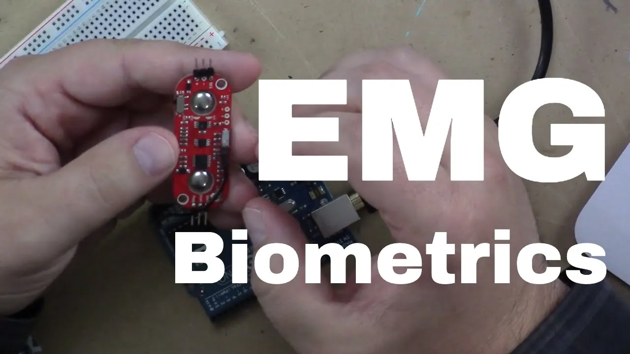
This video explains the practical operations of the MyoWare EMG sensor, an industry-standard component for DIY bionic designs. It details how the sensor detects muscle voltage fluctuations and converts them into a simple analog voltage readable by an Arduino.
Knowledge Checkpoint
- State the voltage output range of a typical MyoWare EMG sensor and map it to Arduino's 10-bit analog read range (0 to 1023).
- Explain the roles of the three sensor electrodes: reference (ground), middle, and end.
- Demonstrate how to properly clean skin and position electrodes parallel to muscle fibers to maximize signal quality.

Why this video
This video walks through connecting an EMG sensor board to an Arduino, focusing on signal paths, common power supply concerns, and interpreting the incoming raw data on a serial plotter.
Knowledge Checkpoint
- Wire an EMG sensor to an Arduino without creating ground loops.
- Read raw sensor values using
analogRead()and display them dynamically in the Serial Plotter. - Explain why standard muscle sensors require reference electrodes placed over non-muscle bony areas (such as the elbow).
Gap Fill: Myoware Sensor Wiring & Calibration on Arduino Uno
While the video pool shows general connections (including specialized Teensy setups in Video 3), a standard Arduino Uno calibration sequence requires specific attention to noise and threshold baseline configuration. Use this step-by-step implementation guide:
Step-by-Step Calibration & Wiring Guide
    +-----------------------------------------+
    |             Arduino Uno                 |
    |                                         |
    |    5V    GND    A0                      |
    +----+------+-----+                       |
         |      |     |                       |
         | Wire | Wire| Wire                  |
         | (Red)|(Blk)|(Blu)                  |
         |      |     |                       |
    +----+------+-----+                       |
    |    +      -     SIG                     |
    |                                         |
    |        MyoWare EMG Sensor               |
    +-----------------------------------------+
- Hardware Connection:
- Connect the MyoWare + (Vs) pin to Arduino 5V.
- Connect the MyoWare - (GND) pin to Arduino GND.
- Connect the MyoWare SIG (Signal) pin to Arduino A0 (Analog Input).
- Calibration Routine (Baseline Extraction): Copy and upload the following calibration code to find your muscle's resting voltage (noise floor) and active contraction peak.
const int emgPin = A0; int sensorValue = 0; int threshold = 0; int maxContraction = 0; int baselineNoise = 1023;
void setup() { Serial.begin(9600); Serial.println("--- Starting Calibration (Keep Muscle Relaxed) ---"); delay(1000);
// 1. Establish baseline noise floor (5 seconds) long sumNoise = 0; for(int i = 0; i < 200; i++) { int val = analogRead(emgPin); sumNoise += val; if (val < baselineNoise) baselineNoise = val; delay(20); } int avgNoise = sumNoise / 200; Serial.print("Baseline Noise (Average): "); Serial.println(avgNoise);
// 2. Capture maximum voluntary contraction (MVC) Serial.println("--- Flex muscle hard now! (5 seconds) ---"); unsigned long startTime = millis(); while (millis() - startTime < 5000) { int val = analogRead(emgPin); if (val > maxContraction) { maxContraction = val; } delay(20); }
// Calculate decision threshold as halfway point threshold = avgNoise + ((maxContraction - avgNoise) * 0.5);
Serial.println("--- Calibration Complete ---"); Serial.print("Max Flexion Value: "); Serial.println(maxContraction); Serial.print("Calculated Switch Threshold: "); Serial.println(threshold); }
void loop() { sensorValue = analogRead(emgPin); Serial.print("EMG_Value:"); Serial.print(sensorValue); Serial.print(","); Serial.print("Threshold:"); Serial.println(threshold); delay(50); }
What to search if stuck: "Myoware muscle sensor calibration troubleshooting", "Eliminating 60Hz hum powerline noise in EMG signals"
Module 3: Actuators & High-Torque Mechanisms
To assist human movement, an exoskeleton must apply mechanical force safely and effectively. This module explores motor types, gear ratios, and torque calculations. You will learn how gears exchange rotational speed for mechanical advantage and how to write Arduino code to drive high-torque servo motors.
Recommended Videos

Why this video
This in-depth lecture breaks down the physics of gears, detailing how torque scale factors relate inversely to output speed. Understanding these fundamental mechanical equations ensures you can calculate and size gear configurations to match real-world physical demands.
Knowledge Checkpoint
- Explain why reducing gear speed increases output torque using the equation .
- Calculate the output torque and output speed of a motor spinning at 2000 RPM with 0.5 Nm of torque connected to a 10:1 gear reduction system.
- Define gear backlash and explain how it can affect the positional accuracy of an exoskeleton joint.
Why this video
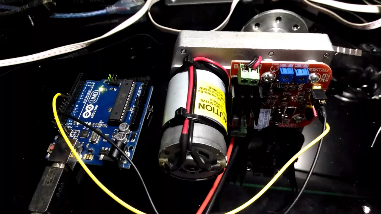
This short demonstration features the ASME-03 high-torque servo motor driven by an Arduino Uno. This heavy-duty servo represents the class of actuators used to build functional, force-multiplying joints in wearable orthoses.
Knowledge Checkpoint
- Explain how heavy-duty industrial servos (like the ASME-03) differ from standard hobby servos in wiring, power, and construction.
- Wire a high-torque servo to an Arduino using an external power supply to prevent burning out the microcontroller's 5V regulator.
- Write a basic Arduino sketch using the
Servo.hlibrary to rotate an actuator between 0 and 180 degrees.
Why this video
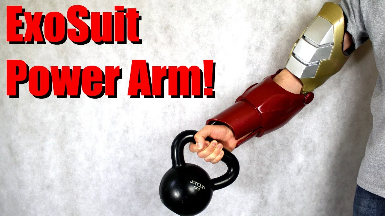
James Bruton shows how to select, mount, and test high-power motors (specifically brushless outrunner systems with significant gear reductions) for a wearable Iron Man suit. It demonstrates how to translate academic torque concepts into physical mechanical engineering prototypes.
Knowledge Checkpoint
- Explain the power density benefits of brushless outrunner motors over traditional brushed DC motors.
- Discuss why high gear reductions are essential when using high-KV brushless motors for joint movement.
- Describe the structural support techniques needed to prevent high-torque motors from ripping themselves off their mounts.
Deep-Dive: Calculating Human Joint Load Torque Requirements
Before designing a physical mechanism, you must calculate the exact torque required to lift a human forearm and an external load.
Where:
- is the gravitational force (, where ).
- is the distance from the elbow joint hinge to the center of mass of the forearm (or the object being held).
- is the angle of flexion relative to the vertical line of gravity (maximum torque occurs at elbow flexion, where ).
Example Calculation
Suppose a user's forearm mass is , with a center of mass from the elbow. The exoskeleton needs to assist in lifting an additional payload held in the hand ( from the elbow).
- Forearm Gravity Torque:
- Payload Gravity Torque:
- Total Required Peak Torque:
Your selected motor-gearbox combination must provide at least 12.36 Nm of holding torque. To ensure safe operation, apply a safety factor of 1.5, meaning your motor must be rated for at least 18.54 Nm of peak torque.
Module 4: Ergonomics, CAD Design & Joint Kinematics
An active orthosis must align perfectly with the human body to prevent injury. In this module, you will learn to use Fusion 360 to design 3D-printable structural components, study how biological joints behave, and learn how to align mechanical hinges with the human body's natural axes of rotation.
Recommended Videos
Why this video
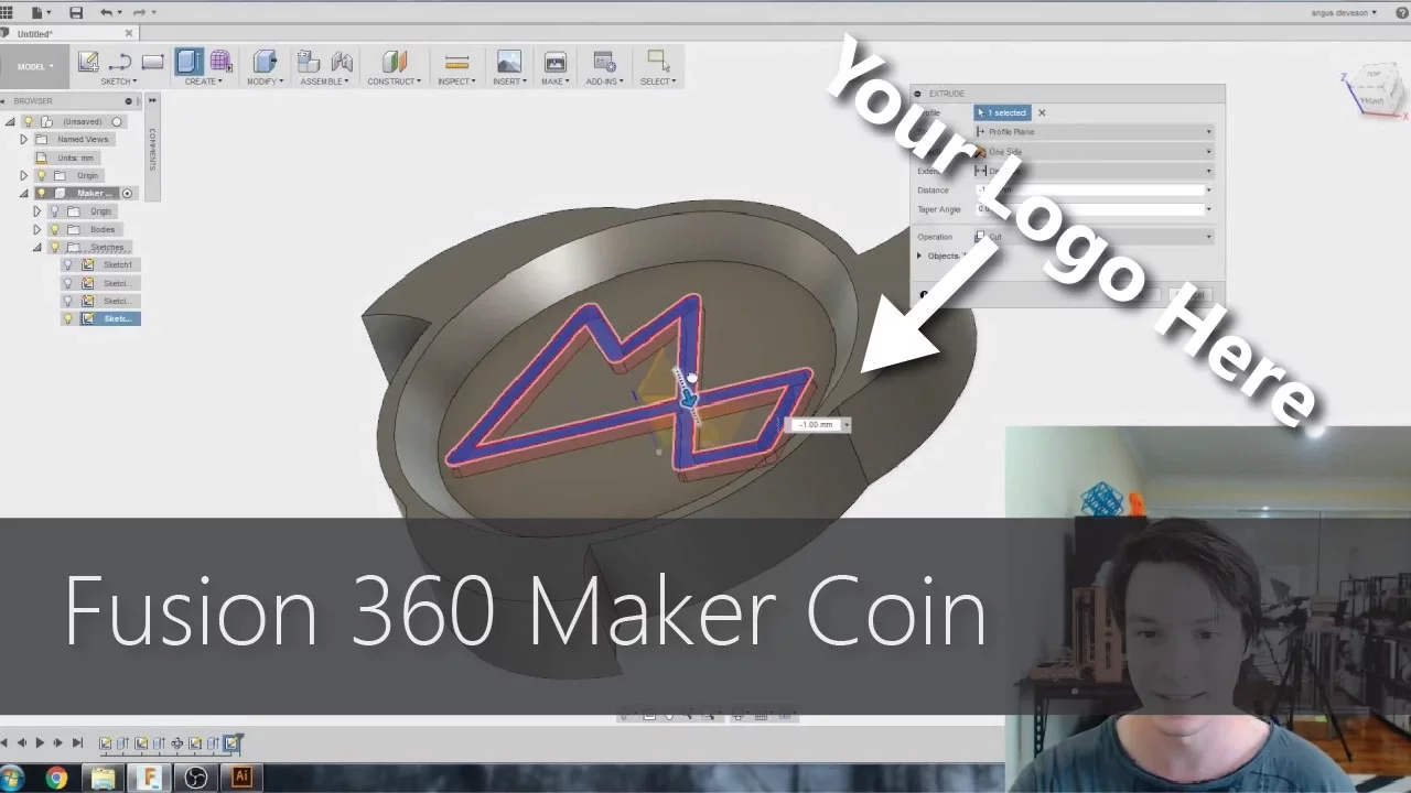
This tutorial introduces Autodesk Fusion 360, focusing on standard 3D printing design configurations. Learning how to navigate sketches, extrusions, clearances, and tolerances is essential for creating durable, wearable brackets.
Knowledge Checkpoint
- Configure default workspace units (mm), navigation styles, and sketch planes.
- Create a dimensioned 2D sketch and extrude it into a solid 3D body.
- Apply physical print-clearance offsets (e.g., leaving a 0.2mm gap for mating parts) to ensure 3D-printed parts fit together properly.
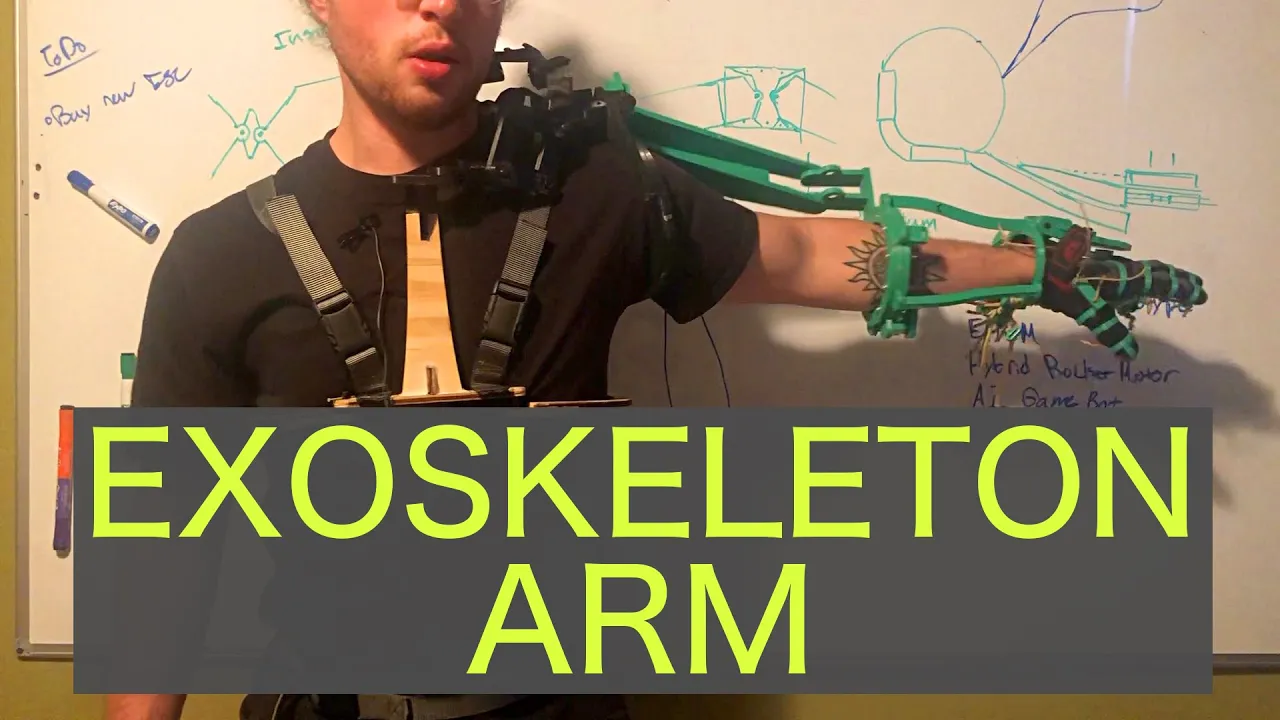
Why this video
This video explains how exoskeleton joints are designed based on biological principles. The presenter explores how human joints move like ball-and-socket joints, even when not classified as such, and highlights the need to build compliant mechanical systems that align with natural human movement.
Knowledge Checkpoint
- Explain how human joint movement differs from simple mechanical pin hinges.
- Define "joint misalignment" and describe its potential physical effects on a user's arm.
- Explain how a compliant mechanical joint can compensate for small misalignment errors.

Why this video
Jamie Hyneman shares insights on designing wearable technology. He highlights the engineering challenge of connecting rigid mechanical linkages to soft human tissue and joint structures.
Knowledge Checkpoint
- Describe how soft tissue compression affects force transfer from an exoskeleton structure to user bones.
- Detail design techniques (such as using wide cuffs, straps, and foam padding) that help distribute pressure comfortably.
- Explain why exoskeleton components must be designed to accommodate different body shapes and sizes.
Gap Fill: Biomechanical Hinge Alignment in CAD
The human elbow is not a simple, single-axis pin joint. It acts as a modified hinge joint (trochoid/ginglymus) with an instantaneous center of rotation that shifts dynamically as the elbow flexes.
         Incorrect Design                     Correct Design
     (Single Fixed Hinge Offset)        (Self-Aligning Sliding Hinge)

             Exo Arm                                Exo Arm
           +---------+                            +---------+
           |  Rigid  |                            | Sliding |  === [Linear Slot]
           |  Hinge  |                            |  Joint  |
           +----+----+                            +----+----+
                |                                      |
             ( Hinge ) <--- Shear Stress            ( Hinge ) <--- Self-adjusting
                |           on tissues                 |           axial center
           +----+----+                            +----+----+
           | Forearm |                            | Forearm |
           +---------+                            +---------+
When a simple mechanical hinge is misaligned with the elbow's axis of rotation, it can generate painful shear forces along the arm.
CAD Best Practices for Elbow Alignment
- Implement Floating Linear Joints: Do not rigid-mount both the upper arm cuff and the lower arm cuff. Design a slot-and-pin linear slide joint along the forearm bracket. This allows the mechanical linkage to expand and contract slightly, neutralizing alignment errors as the elbow flexes.
- Locate the Rotation Axis: Set the physical rotation point of your hinge directly on the lateral epicondyle of the humerus (the prominent bone bump on the outside of the elbow).
- Adjustable Arm Lengths: Design telescoping structural members in CAD using clamping hex bolts to allow custom tuning of both the upper arm and forearm lengths for different users.
What to search if stuck: "Exoskeleton joint axis misalignment compensation mechanisms", "Biomechanically aligned elbow joint design CAD"
Module 5: Signal Processing & Control Algorithms
Raw electromyography data is highly erratic, noisy, and prone to motion artifacts. In this module, you will learn digital signal processing techniques—such as full-wave rectification, smoothing, and envelope extraction—and write state-machine code on your Arduino to trigger actuation safely when muscle activity is detected.
Recommended Videos

Why this video
This video explains the stages of converting a raw, AC-like EMG signal (which fluctuates rapidly above and below 0 volts) into a smooth, usable DC-like amplitude envelope. It details the mathematical steps of amplification, filtration, and integration.
Knowledge Checkpoint
- Explain why raw EMG signals look like high-frequency alternating current (AC) voltage.
- Explain the difference between full-wave rectification and half-wave rectification.
- Describe how a low-pass filter converts rectified spikes into a smooth muscle activity envelope.

Why this video
This video demonstrates raw EMG capture using an Arduino, showing real-time signal rectification and analysis. It provides visual context for how raw muscle signals respond to varying physical effort.
Knowledge Checkpoint
- Setup your Arduino to read a high-frequency raw analog signal.
- Differentiate between background electrical noise and actual voluntary muscle contractions on a live signal graph.
- Define the term "sampling rate" and explain why high sampling rates are critical for capturing accurate raw EMG data.

Why this video
This video explains how to write modular state-machine code for robotic lift systems. This logic structure is vital for creating safe wearables that move systematically through states (such as IDLE, FLEXING, HOLDING, and RETRACTING) rather than behaving unpredictably.
Knowledge Checkpoint
- Define a "state machine" and explain its advantages over simple, nested
if-elseloops. - Create a state transition diagram for an assistive exoskeleton based on muscle input triggers.
- Implement a basic state variable in C++ using an
enumstructure.
Gap Fill: Real-Time Digital Signal Processing on Arduino
While professional tools rely on MATLAB, an active wearable needs to process signals locally on its onboard microcontroller. Since the Myoware sensor outputs an integrated envelope, processing raw signals requires a custom software loop. Use this complete DSP script to implement full-wave rectification and an exponential moving average (EMA) filter on your Arduino:
// Onboard Real-time EMG Rectification & Smoothing (EMA Filter) const int rawEmgPin = A0; const int dcOffset = 512; // Adjust if your raw sensor's zero-point is offset
// Filter Coeff alpha (0 < alpha <= 1). Lower values = smoother signal but higher delay const float alpha = 0.08; float filteredEnvelope = 0;
void setup() { Serial.begin(115200); // High baud rate to handle rapid processing }
void loop() { int rawRead = analogRead(rawEmgPin);
// 1. Full-Wave Rectification: Remove negative voltage components relative to virtual ground int rectified = abs(rawRead - dcOffset);
// 2. Exponential Moving Average Low-Pass Filter (Envelope Extraction) filteredEnvelope = (alpha * rectified) + ((1.0 - alpha) * filteredEnvelope);
// Plotting values to compare raw data with the processed envelope Serial.print("Raw:"); Serial.print(rawRead); Serial.print(","); Serial.print("Rectified:"); Serial.print(rectified); Serial.print(","); Serial.print("Envelope:"); Serial.println(filteredEnvelope);
delay(2); // ~500Hz sampling loop rate }
What to search if stuck: "Arduino digital low pass filter algorithms", "Onboard raw EMG signal envelope extraction C++"
Module 6: System Integration, Power & Safety
In this final module, you will integrate your mechanical, electrical, and control subsystems into a functional, wearable prototype. You will explore high-density lithium-polymer (LiPo) batteries, learn essential battery safety and protection protocols, and walk through testing and calibrating your wearable device.
Recommended Videos

Why this video
This video explains how to select, read, and safely use lithium-polymer (LiPo) batteries in dynamic robotics applications. It covers cell configurations, voltage levels, and capacity ratings.
Knowledge Checkpoint
- Explain what the S-rating (e.g., 2S, 3S, 4S) of a battery pack means and calculate its nominal voltage.
- Define the battery "C-rating" and calculate the maximum safe continuous current draw for a 2200mAh 25C battery.
- Describe the voltage thresholds at which a LiPo battery cell becomes permanently damaged or dangerous.

Why this video
This guide details how to handle, charge, and store LiPo batteries safely. Since bionic devices are worn on the body, understanding battery chemistry, balance-charging, and fire safety is a non-negotiable prerequisite.
Knowledge Checkpoint
- Set up an intelligent balance charger with the correct chemistry, current rate, and cell count parameters.
- Explain why balance charging is critical for multi-cell (2S+) battery packs.
- Detail the proper disposal steps for physically damaged or bloated LiPo batteries.
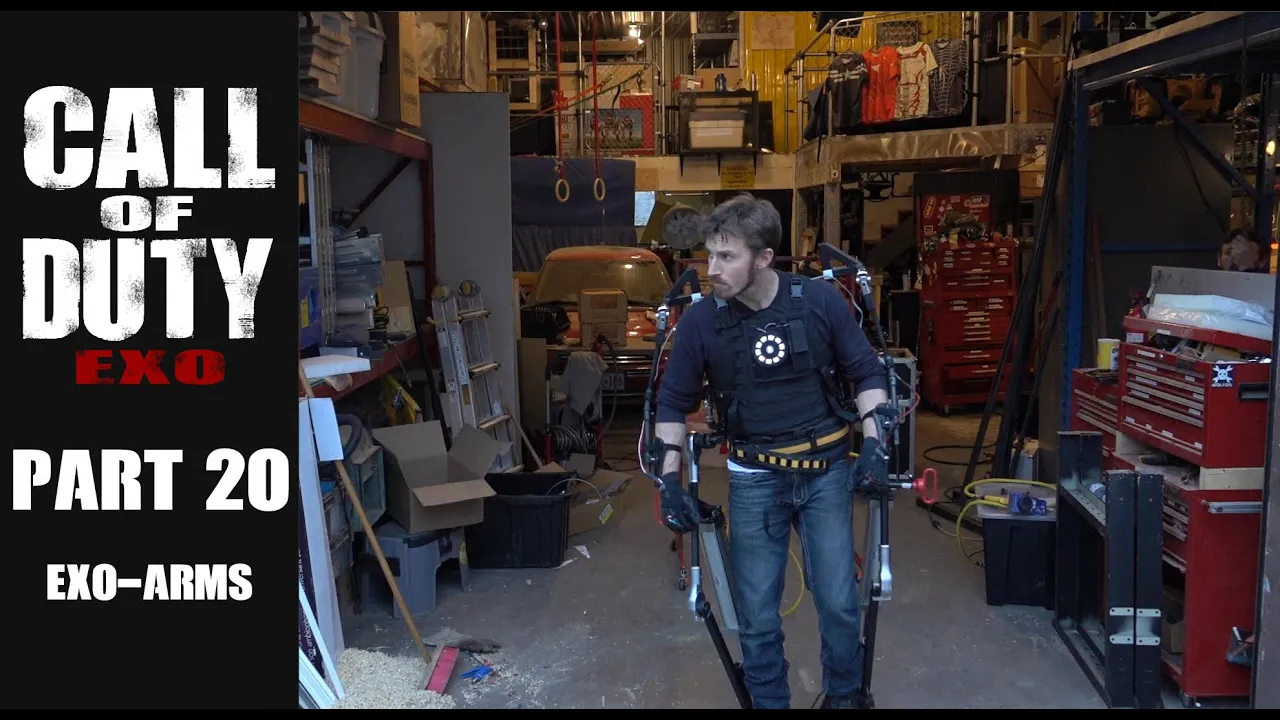
Why this video
This video from Hacksmith Industries demonstrates structural mounting, quick-release harnesses, and real-world biomechanical testing of upper-body exoskeletons. It illustrates the iterative engineering steps needed to refine a wearable prototype from a lab setup to a functional system.
Knowledge Checkpoint
- Design quick-release strap mountings that allow the wearer to quickly disengage from the exoskeleton in an emergency.
- Identify key structural stress points where components may fail under load.
- Perform a systematic, unloaded test of your exoskeleton to verify control loop accuracy before wearing the device.
Course Map
This map outlines the path of learning and system integration, showing how each module builds toward the final wearable prototype.
Key People Index
- Paul McWhorter (@paulmcwhorter)
- Context: A prominent STEM educator who teaches practical microcontrollers and electronics. His foundational videos explain programming and circuit layout clearly for absolute beginners.
- James Bruton (@jamesbruton)
- Context: A robotics designer, mechanical engineer, and former toy designer. His experimental bionic suits show how to translate physical mechanical engineering concepts into functional, wearable prototypes.
- Jamie Hyneman (@Udacity / Mythbusters)
- Context: Renowned special effects designer and prototype engineer. His insights highlight the challenges of interfacing rigid mechanical components with soft human tissue.
Final Self-Assessment
Complete this checklist to verify you have met the learning goals of this curriculum and are ready to construct your active upper-limb exoskeleton:
- Physical Circuit Design: I can wire an Arduino Uno, breadboard, high-torque actuator, and MyoWare EMG sensor together with an external power source without creating short circuits or ground loops.
- Arduino Firmware Development: I can write custom code in the Arduino IDE to read analog inputs, execute comparison functions, and write high-resolution position outputs using the Servo library.
- Biomechanics: I can explain how voluntary muscle contractions generate small surface voltages and how to position surface electrodes parallel to muscle fibers to capture these signals.
- High-Torque Calculations: I can calculate the physical holding and lifting torque requirements of an elbow exoskeleton joint based on forearm mass, payload mass, and mechanical linkage lengths.
- Ergonomic CAD Modeling: I can use Fusion 360 to model high-tolerance mounting brackets, linkages, and arm cuffs that align with the human elbow's axis of rotation.
- Real-time DSP Filter Implementation: I can explain and write Arduino C++ code to perform full-wave rectification and exponential moving average (EMA) smoothing to extract a clean signal envelope.
- State Machine Logic: I can build structured control logic with safe state transitions (Idle, Flexing, Holding, Retracting) to handle real-world muscle signals.
- LiPo Power Safety: I can identify LiPo cell types, calculate continuous current discharge limits, safely charge multi-cell battery packs, and implement mechanical emergency quick-release straps on my prototype.