












![KTOM : GEARS & GEAR TRAINS (11) Problem-6 [Compound Epicyclic Gear Train - 2] by Tabular Method](https://i.ytimg.com/vi_webp/i5xrzTB7ZrA/maxresdefault.webp)







![The M-19 Tank Transport Vehicle - Part 1: Functions - With Original Narration [ WWII Documentary ]](https://i.ytimg.com/vi/ji9pAeJqddg/maxresdefault.jpg)


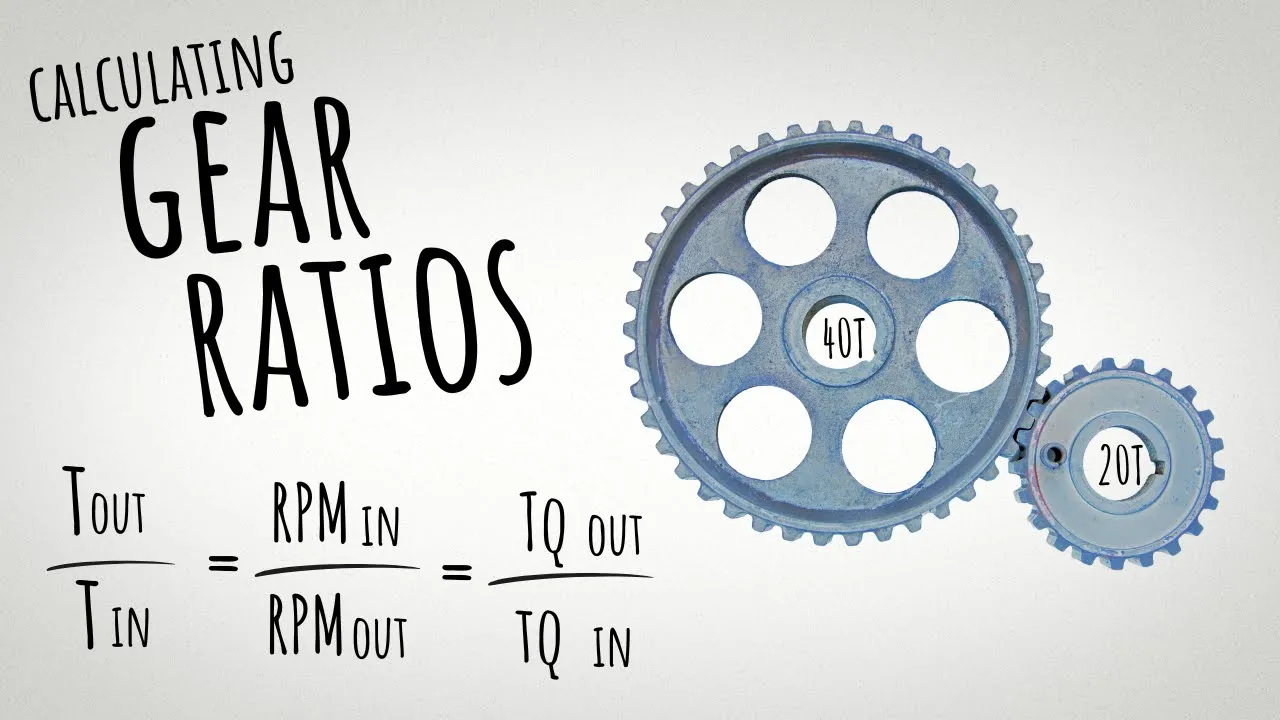
In gear trains, torque and speed are inversely related through the ratio of gear teeth: torque increases when transferring to larger gears (T₁/T₂ = N₂/N₁) while speed decreases proportionally (ω₁/ω₂ = -N₂/N₁), with the negative sign indicating that meshing gears rotate in opposite directions; pitch circles model gears as friction rollers for analysis, and idler gears only reverse direction without affecting torque ratios.
Gear Torque and Speed Relationships | Motor Winch Geartrain Problem
Added:Basic concepts of rotational motion, including angular velocity (RPM) and angular displacement.
The definition of torque as a rotational force (Torque = Force x Distance) and its standard units.
Fundamentals of mechanical advantage and how simple machines multiply force or speed.
The relationship between mechanical power, torque, and angular speed (Power = Torque x Angular Speed).
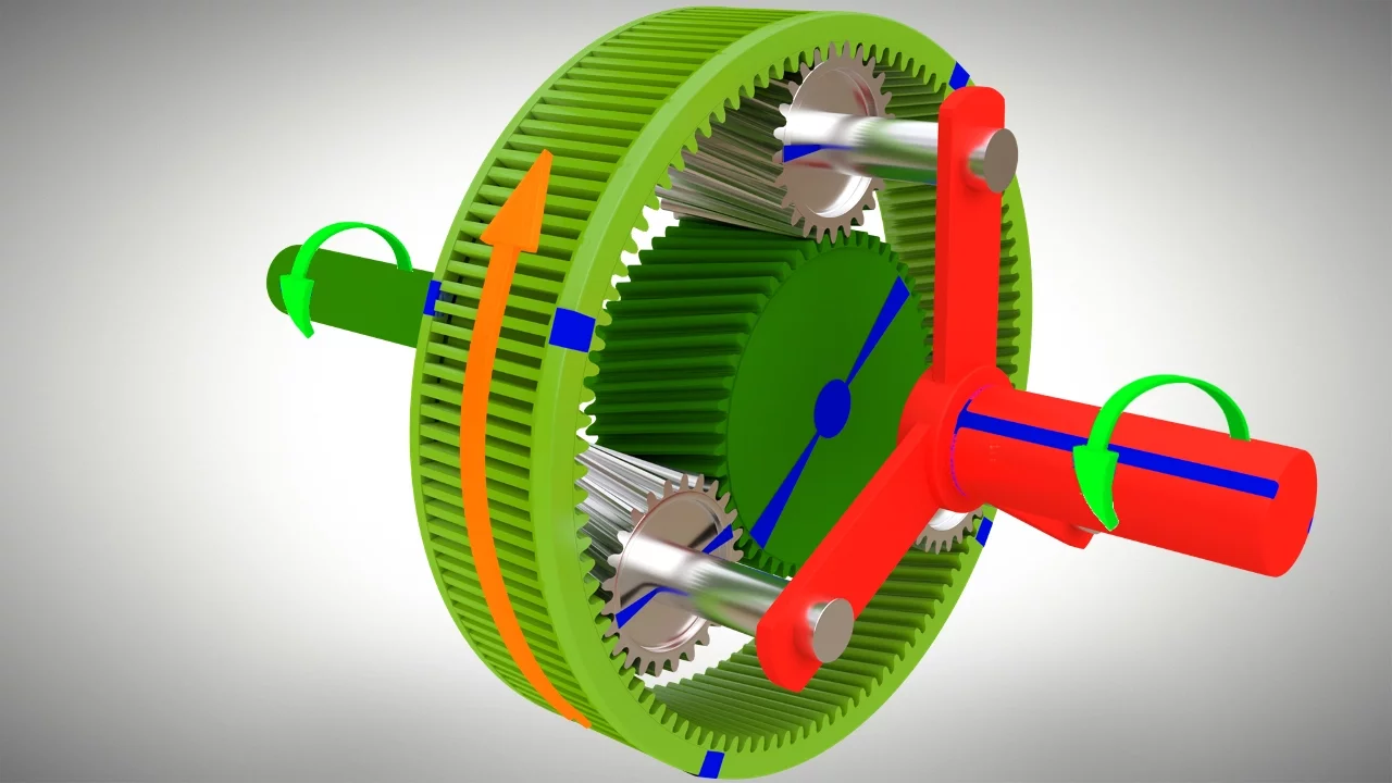
Analysis of compound gear trains and planetary (epicyclic) gear systems.
Calculating gear train efficiency, mechanical losses, and accounting for friction and backlash.
Motor selection and matching motor torque-speed curves to specific mechanical load requirements.
Designing real-world hoist and winch systems, including safety factors, braking mechanisms, and structural limits.
96.1K views1.9Klikes1:01:57Original Release: 2018-03-31
all right we have all come across gears in various devices that we have dealt with so gears are elements that allow you to transmit rotational motion and torque from one axis - another axis across an element that has teeth on it okay and so what I'd like to start with here is just a few basics right at the very front end about how we are going to be thinking about gears okay so the first thing I'd like to point out is you know gears do have teeth on them right there's these little protrusions out of each side those little protrusions mesh with one another that's a word we use mesh it means that they are actually sort of interacting with one another so that they're sort of the envelope of one piece is inside the envelope of the other piece and that's how they transmit torque but there's a little bit more as far as conceptually how we should probably think about this the first thing I'd like to do is show you that there are these conceptual circles that are inside of the gear teeth that are called pitch circles okay so I'm gonna draw that roughly right here or so for this gear okay there's a circle something like this okay and there's another circle for this other gear then I'm gonna put right here and the way to understand these things that are called pitch circles these are the size of the circles that you would have to have in order to make the behavior the same you know the behavior of the gears the same as if you have sort of two drums rolling against each other imagine you know two pens like this that are round and they're just rolling against one another right there are these conceptual circles inside of the gears such that if you pick them properly the behavior of the gears with teeth on them behaves exactly the same as if you had friction rollers that were just rubbing against each other okay does that make sense sound good so far all right so those are called pitch circles and that enables us to basically for most of our conversations that we have in this in this class we are not really going to try to draw all the teeth of each of the gears that we are drawing instead what we're going to do is draw these kind of like this okay will you'll either see drawings that may look something like this where you have you know sort of a three-dimensional representation of one gear that is meshing with another gear something like this right so maybe maybe you'll see something oriented like this where you've got the two gears mating with each other or what's even more common than that instead of like a 3d view of it we actually just show it as two circles something like this okay and that's how we're going to deal with the gears that we have in here okay the next thing I want to kind of do is mention that the gears don't stay located in space all by themselves all right something has to keep them located where they are what do you think that might be okay so we've looked at various kinds of mechanical connections and one of them that we've looked at is a pin how does a pin work okay I hear that it a pin allows things to revolve but it does not allow things to translate that sounds like exactly what we need for the Centers of these gears okay we need it to be able to revolve but we don't want it to be able to translate and so what you might see a lot of times is that there would you know where physically there might be a pin inside of this gear and inside of this gear and then those pins you know would actually be connected to some you know some kind of thing that's fixed right that's physically what would be going on with the gear the way we would model that a lot of times we would show just like we do with other things we show these little pins and that indicates that at the center of these gears the middle is not allowed to translate left right up or down and yet the two parts are allowed to rotate so one way of saying this is that gears themselves typically behave as non-concurrent force systems right same type of rules apply to gears as any other kind of non-concurrent force system okay let me show you another picture real quick okay what's going on there okay how does that particular gear train work okay let's say you're let's say you're putting a torque in at shaft a okay so you're you're basically putting a torque right here what happens okay what we can say for sure is that it transmits torque through the gear train right and then we get torque out of the other end okay let me do this so if there is a motion so how would this thing move let's say pin you know gear number one let's say it also rotates this direction okay so I'm going to use green arrows to depict motion red arrows to depict torque okay if the if it's actually turning the direction that I show there because it doesn't have to turn the same direction you put torque on it right that's an important point would you agree with that okay you may not have thought of that before but you know if two people are fighting over what direction to turn something someone can win right which means that the person that lost is putting torque on in a direction that it's not actually turning okay so this this happens you know it's one way of looking at anyway this happens in gear trains so let's say that the green arrow shows the direction it's actually turning what direction will the next gear actually turn okay turn this way and then the next gear okay what do I mean by the next gear okay that's what you guys are asking the exact right question what do I mean by the next gear okay so what we see here is that we've got gear one that one's pretty unambiguous what about this next one okay - and three are actually attached together they are actually one part even though I've got two gears it's like they're fused together and someone over here actually used the term compound gear that is what that's called if you have a gear that's got two of them there it's called a compound gear okay and so both of those are turning the same direction because they're connected to each other so the next gear in the train is actually the one well which one is that you tell me four and five right what direction will four and five turn okay turn that way and what direction will the last gear turn counterclockwise okay so we can look at something like this and knowing what direction the input is we can figure out what direction the output will go okay we very very seldom will actually draw a gear train like this why do you think that is that it takes a little bit of talent to actually draw that right and sometime yeah even if you've got the talent you may not want to spend the time right so what do you think how do you how do we draw something like this okay usually in 2d so like we might draw a gear one like this we might draw a gear two like this okay with gear three in here like this and then what gear 4 might be over here like this and I'm just getting a rough idea here of how this might go okay it's you know makes it make more sense usually if you can erase some of the lines you know that helped it kind of make sense how they stack what about the next one okay there's another gear that's kind of on the inside of this one okay would you agree with that and then what okay then there's this one that's kind of over here but I'm probably still missing something what do you think what other things should I probably have on there some pins okay to kind of indicate that these can all rotate around these places okay something like this that input torque that I put right at the very beginning I'm applying it to the shaft going into gear a right do you agree with that how would I depict that on my 2d drawing usually what we do is we just show a torque like this and we understand that that means we're applying a torque to the shaft that's at the middle of that gear that's usually how we communicate the idea that we're applying a torque to the shaft and then that is then transmitted through the gear train okay all right we'll get into so the the idea of what the torque does as far as how it changes direction as it moves to the gear train is a little bit more complicated than the question of direction and so we'll get into that here with our next conversation and and so what we're gonna do here is actually derive relationships that allow us to say how much torque is transmitted from one gear to another okay I think I missed one other concept up here before I get to that what I was just gonna bout to say there I missed one concept in order for these gear gears to actually mate with one another you can't just make the teeth any old size that you want like you can't have one gear where each tooth is about an inch big or inch wide and another gear where each tooth is a tenth of an inch wide and expect them to mate with one another right so there's there have to be compatible gear teeth is one of the concepts I meant to touch on back when we were talking about teeth on these gears and that goes into this idea of the pitch circles as well we actually refer to a number of different kinds of pitch of a gear and pitch basically refers to how many teeth do you have per unit of length okay so there's there's a couple different kinds of pitch that we talked about one of them is called circumferential pitch what do you think that means yeah how many how many teeth per unit of circumference right or diametral pitch what do you think that means how many teeth per unit of diameter right there are two different numbers but they're actually related to one another and so this is important because in order for Gears to actually mate with one another they have to have the same pitch and that's going to be important to us here in our next little conversation all right let's think about gears from a free body diagram standpoint so let's say that I've got two gears that are mating with one another I put one gear right here and I put another gear right here okay there's a pin at the middle here a pin at the middle here let's say I know some things about these gears let's say that I know the radius okay so the radius of this gear I'll call it R 2 and the radius of this gear I'll call it R 1 okay let's say I'm also putting in a torque into gear one that I will call t1 and at what I'd like to do is figure out how much torque do I react on gear two if I want this thing not to accelerate right that's for all of our questions that we're talking about in this class we're doing statics problems right statics problems are ones where there's no acceleration either angular ly or linearly okay so we're gonna limit it to that how much torque do I need to apply to gear two to keep it from accelerating so I'll put that on as t2 all right so what do I do that's what I'd like to figure out I'm putting on t1 I'd like to know how much does t2 have to be so it so that it doesn't accelerate okay do they have to be the same as each other like the exact same number well let's figure that out what's our tool we do things with in here Freebody diagrams dr. Swan bomb that is right we use Freebody diagrams in this in this class and so what we are going to do is draw Freebody diagrams of these two elements okay we have one here one here okay if they are Freebody diagrams we don't want to draw them with bearings shown what do we do instead what do the bearings do right in terms of forces that's what we think about okay we know that the bearings do not allow translation vertically or horizontally okay so maybe I will say this is a reaction for gear number two in the Y direction this is a reaction for gear number two you in the x-direction make sure I don't reverse these this time what else okay we have this the same idea over here okay there are a couple of reactions that we probably want to think about here are 1y and r1 X smaller so it's a little bit more to fit in there what else okay we have a torque of t1 being applied to the upper gear right so I just go ahead and put that on like this and say I've also got t1 all right I could do the same for the other one there's another torque T 2 so this is what we kind of knew from the beginning now what yes sir so what I'm doing remember always on your Freebody diagrams if you don't know the direction you pick a direction and then you work through the details and we get to the end your sign tells you whether you were correct or not you're sitting right that's right you're whether you have a positive or negative tells you where you right or were you wrong okay well as I look at these two diagrams right here they don't look to me like they can be in equilibrium yet why not neither one of them can be in equilibrium right now okay they look to me like both of them are going to start spinning out of control why what's that Newton's laws right right now if you take the sum of moments around the midpoint the middle of gear 1 what would you have for that sum T 1 right there's if T 1 is non zero then this thing is going to something's going to accelerate so what we're basically doing is we're missing one of the forces that must be applied to that first gear ok yes sir yeah so there's actually we took these two gears apart from one another and you'd expect that there'd be some interaction that happens between the two gears and that's what we're missing the contact force between them now the actual contact force between these gears is in real life a little bit more complicated than the model that I'm going to show you okay but the model I'm going to show you works for basically everybody who doesn't necessarily care to get you know all the really nitty-gritty details like exactly perfect reactions at the bearings for instance okay if you don't care about getting those and all you care about is torque transmission through the gear train the model I'm showing you here works just fine so the model I'm going to show you says that this gear contact force is going to happen along a tangent line to where the contact is occurring okay that tangent line up here would be right there okay so what direction for gear number one what direction would the force have to act to keep it from accelerating okay it has to probably counter the direction that the torque is trying to turn it which would be this direction okay and let me just call that F what about for gear 2 okay well there's two ways we can think about gear two what I'd like to do is remember Newton's third law that says for every action there's an equal and opposite reaction so I better draw this force of F going the opposite direction because it's supposed to be equal opposite okay and and that is correct like that's what we would need to have on there in which case we can do a quick little you know equilibrium equation using moments around the pin for gear number one and what do we have there guess I also need to put on a radius value here too right so the radius here is our 100 it's easier for me to show the radius right to where it matters on this other one okay by some moments around the pin for gear number one what does that equation look like okay let me let me make counterclockwise positive okay I have negative T 1 then what plus F times R 1 and that's all of my moments that carry all of my forces that and other influences that create moments around the pin okay so let me actually solve this equation right here for F okay what is F okay let me do the same idea down here for the other Freebody diagram right so that was my upper Freebody diagram what about for this lower Freebody diagram some moments around the pin what do I have okay t2 or negative T - negative t2 as I showed it clockwise alright negative T - okay plus F times R - that makes a counterclockwise tendency to rotate correct the F tends to try to rotate this thing counterclockwise and this tells me that F is equal to what t2 over r2 this F is the same whether we're talking about this one or this one right those are the same force so what can I do with this now okay T 1 over r1 is equal to t2 over r2 and if I want I can actually rearrange this a little bit and say t1 over t2 is equal to r1 over r2 okay I'm going to start this actually on a new line down here what happens if I multiply numerator and denominator of r1 and r2 by 2 does it give me diameters the ratio is the same right so in other words I can multiply any constant by a numerator and denominator and it doesn't change the value of that fraction correct so if I multiply numerator denominator by 2 it gives me that the diameter of 1 over diameter 2 is equal to torque 1 over torque - okay what if I multiplied by pie okay has to equal the ratio the circumference --is as well all right the next one's even a little bit more tricky what if I multiply by circumferential pitch because remember a circumferential pitch has to be the same for both gears right that's the number of teeth per unit of circumference what if I multiply both numerator denominator by circumferential pitch because has to be the same for the two of them okay so let me I'll label under here what I mean these are numbers of teeth these are circumference --is these are diameters these are radii and of course these are torques all of these ratios work okay if I'm talking about things that have to do with the circle the radii the diameters the circumference is what am I actually talking about is it is it a radius diameter circumference that you could measure with a tape measure from tooth to tooth or not it's not right what is it well it's it's that pitch circle I was talking about right there's this theoretical pitch circle that happens where the gears are mating like they're supposed to and it makes the gears behave as if they are just two cylinders rolling against one another okay so that is that gives us our relationship the one we will use most often is this relationship between torques and numbers of teeth okay do you think we can do something similar for speeds if you're nodding your head then I agree with you okay so real quick before I really start talking about the discussion of speeds talking about rotational speeds here let's think about how fast you know the instantaneous velocity for something that is rotating right let's say this thing is rotating with some speed there's an instantaneous velocity right on the surface how can we determine what that instantaneous velocity is okay well let's say what's our most common way of conversing with each other about rotational speed someone says rpm right usually in common discussions that you have with people rpm is the most common way of thinking about speed so let's say that you have here revolution per minute okay how fast is this velocity going to be what does it depend on yeah it probably depends on the size let's say let's do it in terms of diameter here the size of this drum and the way that I like to think about this is what if you have string wound up on this drum all right you've got this string that's on here and you're unwrapping the string let's say you do one revolution how much string do you unwrap PI D okay one circumference worth PI D okay so if you have your rotational speed given in revolutions per minute then if you take that and you multiply by PI D what you're really doing is PI D per revolution this gives you how much length has moved per revolution this basically gives you a linear speed right because you D is going to be in length and minutes is it as a time unit and so this is going to be a speed that makes sense okay so that's kind of where I wanted to start with this idea is you know how can you come up with if you have an RPM how fast is the is a point on the surface moving there is another way to do this by the way some of you may have seen a different way to do this I am intentionally leaving that for statics one so anyway this is this is probably the most intuitive way to understand it all right so let's do this let's look at our two gears again that we're mating with eat with each other okay and this time let's look at look let's say that this one here has a speed and I'll just use the you know speed one and to make it interesting I'm going to assume that this other one has speed two going in the same direction okay and we have the same relationships here as well where we have a radius R one and a radius R two all right how am I going to relate speed one to speed - do you think it's not really a free body diagram but instead it's kind of a kind of like a geometry diagram it's more appropriately probably called a kinematic diagram but I'm going to split these again and show just one gear along with another gear okay and what do you think we can say about the point of contact between these two gears that was kind of the critical thing that we did with the last one right was right there with a to contact each other there was a relationship that allowed us to do the rest what do you think how do you think it works here okay yeah the instantaneous velocity right at the point of contact how should they be related to one another they're equal okay so it looks like based on the fact that I said this one has a speed going this way okay this one has a speed going exactly the same direction at exactly the same speed okay maybe I'll call that V for velocity okay how does speed one relate to V let's say speed one is in rpm you multiply by what yeah two PI R right you basically say speed one times two PI R is equal to this velocity okay and that's going to be probably in you know again in a a speed per minute if it's in rpm right okay so then I come down here and I said I have a V going this way and I said my speed too was going this way does that actually work yeah there those two are not actually you know kind of compatible with one another the speed going that way does not actually create a linear velocity going the other way but that's okay because we can handle it with a negative sign okay so down here I would say that negative speed 2 is what okay remember this is our - this has had an r1 so this one's going to be equal to we'll say speed 2 times 2 PI R 2 is equal to V up here this was supposed to be r1 okay now what do we do okay so we set them equal to each other because this V is this V so si is you know speed 1 times 2 PI R 2 of R 1 is equal to speed 2 times 2 PI R 2 and that's one of them should be negative yes okay so there's a few things we can do with this we can say here that speed one over speed two is going to be equal to what okay we can do that or we could even divide out the two pies if we want we could basically say that we have negative R 2 over R 1 what if I multiply numerator denominator by 2 put that back in there we have yea negative D 2 over D 1 if those are diameters if I multiply by PI again that gives me back to where I was right but it gives me c2 over c1 negative yes thank you and what else yeah so this relationship still works exactly the same n 2 and 1 okay and again negative the negative basically means that when you've got two gears meshing with each other it will change the direction that they turn we saw that right at the beginning you all already knew that ok but this is I guess we did it slightly more formally all right that is basically what I wanted to touch on today what I want to do next is an example problem okay you ready for an example problem all right let's do that all right so here is a gear train we are basically powering this gear train with a motor the motor has a 20 tooth gear on the output shaft of the motor it goes in it interfaces with a 47 tooth gear that is actually a compound gear with a 15 tooth okay so you all use that term earlier I'll go ahead and point it out on here this is a compound gear okay do we have any other compound gears okay tricky question it looks like there is another compound gear but there isn't okay the reason it looks like there is is that that 56 tooth gear has another circle on the inside but what I'm trying to show you what that circle is not that it's another gear but it's what it's like a little spool I actually put a few different terms that we sort of used them mostly all synonymously in here spool or a winch or a capstan are different ways that we can express that we have a cylindrical shape that we are winding a rope up on or a rope or a cable that kind of thing a flexible element okay so there isn't there's only one compound gear in here and it's that one that is the 47 tooth and the 15 tooth okay so what we want to do first of all we want to assuming that there aren't any losses we wanted we want to figure out how much torque we need to apply with the motor so that we can lift the the weight at some speed what speed you want to make it lift I'll give you some freedom here 2424 what 24 unicorn's okay well it might be a little bit awkward here because what I've given you the diameter of the spool in inches and I've given you the mass in kilograms and those are dissimilar unit systems okay I don't do that very often but I'm doing it here so that you see that real-life can do this to you okay like you don't always get the choice so sometimes I'm not gonna give you the choice so what speed do you want it to go centimeters per hour now let's make it a little faster inches per second I like that alright so inches per second now what often that is the correct answer although it seems like maybe it's not as often as I as I once thought all right this one is one where you probably don't necessarily need to do a free body diagram what do you think a good first step might be okay how about this how about we figure out how much torque is being applied to the spool that sound good so how do we do that okay first we come up with how much weight do we have there right we can't do a torque until we have a weight 79 kilograms is what okay 79 kilograms times 9.81 m/s^2 gives us what what are the units that come out of that okay that comes out in Newtons right kilogram meter per second squared is a Newton that is definitely one of those things that you want to lock away in your memory don't lock it too deep though okay so seven seventy nine point seven seventy four point nine nine Newtons now what okay so that's how much force I've got there and do you really want to do a free body diagram all right well then you probably should okay okay is tricky question okay let's let's look at a free body diagram of the 56 tooth gear okay and what we have there is a force that comes here this isn't a free body diagram right what do I need to do instead just show the pin and then what else do I put there the reactions right okay so let me I'll just call that our pin in the Y and this I'll call our pin in the X okay and here what's that force that I've got coming down right there seven seventy four point nine nine Newtons what else do I need on my Freebody diagram axes okay what else okay I probably need how far is it from the line of action of that force to the place where I'm likely to some moments around okay two inches and then the last thing I'll do is I will show the torque being applied on the fixed 56 tooth gear okay and it's okay you don't have to just always do it blindly it's okay for you to do it in a smart way I know it's gonna be applied this direction right how do I know that it should react against what's pulling on the string right or the rope so let me call this you know I'll just say this is t spool all right how much is T spool rather than just going right to T spool I'll do it more formally where I some moments around the pin then what T spool then what okay seven seventy four point nine nine Newton's times two inches okay do you like those units okay there's nothing technically wrong with them all right but I don't like them why don't I like them I usually like to get into some kind of a consistent system if possible so what do I do to get that into a consistent system okay here's the the ones I know off the top of my head I know that 2.54 centimeters is an inch okay what else okay I actually might not want this in Newton centimeters I might want it in Newton meters so then what I might want to put you know 100 centimeters are in a meter okay both of those terms that are in the blue parentheses there those are just other ways of writing one so I can multiply by those and it doesn't change anything and that's everything I've got that creates moments around the pin okay so now how much is T spool okay it'll be seven seventy four point nine nine times two times two point five four divided by a hundred and that gives me a number that's in what newton-meters thirty nine point three seven okay well now what well we haven't quite gotten there yet right now I've got tea on the spool my first bullet I'm asking for is what okay I need to know how much torque does the motor need to apply right that's the shaft over on the motor end so what do I need to do with this tea spool okay where's what we do we do t spool okay we'll say T spool over T motor what's this ratio gonna be okay so what we got to do is trace it through all of our gears right so first of all do I have less torque or more torque on the 31 to that on the 56 tooth okay the ratios are always for torques anyway the ratios are always direct right so I go 56 teeth over 31 teeth but that gets me to the 31 to that then what ah good job everyone smile check y'all okay so now what okay 47 teeth over all right or another way to do this is to basically say if I want the torque on the motor right I can basically flip all of those ratios right and and multiply by it that way I maybe should have done it that way in the first place but oh well here's what we've got so that I'll write it out again T motor is going to be equal to T spool times what 31 teeth over 56 teeth times 15 teeth over 31 teeth times what okay 20 teeth over 47 teeth okay I'm just it's the same equation I'm just solving it for t motor okay so I take this thirty nine point three seven that I got just a second ago and I multiply it by thirty one times 15 times 20 divided by fifty six I need to put some parentheses there 56 times 31 times 47 ah you guys are very astute so I need four point four eight seven Newton meters of torque at the motor to make this happen a comment was just made down here comment was couldn't you just cancel out your 31 teeth like this okay answer is yes you can does that mean that the 31 2010 as if it's not there but it does not actually affect the final outcome of the torque ratios in other words I could take that 31 to that I want and it will not change the ratio of torque between the output and the input okay because of that this gear also has a tighter this type of gear also has a name this is called an idler gear okay the only thing it does is reverse the direction it doesn't change anything in terms of torque ratios okay and you can see that how it plays out in the math all right so we basically now have done the first bullet point their second bullet point what direction should the motor turn so that we lift the weight okay instead of dropping the weight so how do we do that to lift the weight we need to go what direction probably need to go that direction for the first you know for the 56 tooth gear which means 31 to 36 47 tooth and 15 tooth counter clockwise which means the motor goes clockwise that's it okay and the answer up here was four point four eight seven Newton meters okay basically what you do is you look at each body right so you know each body that has a its own ability to turn and so each time you do that each time you have a gear mesh it reverses the direction so I knew it had to be counterclockwise at the first one in order to lift the weight that's the only way I get this going up is for it to turn counterclockwise right so that's how I knew the first one the second one I just reverse it and said that one's got to be clockwise right because it meshes right here okay the next one meshes right here okay and then so that I have to reverse it again it goes back to counterclockwise and then it meshes again right here meaning as it goes back to clockwise yes ma'am that's right if you were if it's a DC motor and you reverse the polarity on the DC motor it would make the motor turn the opposite direction and it would lower it okay so now we've done the first two bullet points up there the next one is how fast should the motor turn so that we lift the weight at 24 inches per second of velocity okay so where should we start with that one okay we start at the spool again because that's where we know our information so what do we do at the spool okay remember we had that speed if we want to go for a for the case of a string winding up around a drum right speed times what d or pi d if speed is an RPM right a speed is in the you know where the units of the angular speed are given in revolutions right you multiply by how much length per revolution which is pi d and that gives you linear speed okay so for us we know that it's 24 inches per second for our linear speed okay and we divide this by pi times D D is four inches okay and this is going to give us a speed where the angle of basis for the speed is revolutions okay so this ends up giving us what will say 24 / pi times four so one point will say one point nine one units revolution per second what if I want that in revolutions per minute okay I need to get rid of the seconds right so I put in 60 seconds in the numerator and I put in one minute in the denominator so that gives me one hundred and fourteen point five nine rpm okay and that's the speed of the spool so maybe I should put that in right here the speed of the spool how do I get the speed of the motor okay so you can do all the negatives if you want it will give you the same outcome the same conclusion as you did just by doing the directions like I did I actually always do a check on myself that way for my direction right I find that much more reliable than trying to chase all my negative signs correctly through my whole calculation okay but either way works as long as you do them right so the speed of the motor is going to be equal to the speed of the spool times what okay maybe we'll do it this way speed of the motor over the speed of the spool is equal to what okay so remember what you're doing OOP that wasn't good remember I don't know why it's doing that to me here all right we'll just leave it alone you have to reverse and not put the number of teeth in the same sort of orientation in the ratio you've got to reverse them right you've actually got to take the reciprocal so when we've count numbers of teeth here okay what do we put in the numerator for our first one okay so motor per spool all right okay so we'll put in like 56 I'm gonna drop all my units of teeth so 56 over what yeah we can't go all the way to the 20 because what we do is go 56 to 31 and then we multiply what 31 to 15 then we do what okay the next one that we use is 47 to 20 okay and you'll notice here again that that idler gear has no effect on the speed the relative speed between the shaft of the motor and the stand the output speed of the spool that's winding up okay so here we go tell you what this actually I want to do is this you can kind of see by multiplying the speed of the spool on both sides this is what I was going to do at the very beginning until I moved it over see how that's equivalent okay and I know the speed of the spool is 114 point five nine hour p.m. so what I need to do is take that and multiply it by 56 times 47 and divide it by 15 times 20 oh I forgot the very first part of it didn't I all right I need the hundred and fourteen I knew something was off there 100 14.5 nine times this there we go one thousand and 5.34 well see i did because you'll notice here i was doing the ratio of motor to spool and yet the first ratio i did here i put spool and then the one closer to the motor right so I actually did reverse all these ratios yep well I think maybe your question is you'll you'll notice that my ratios are actually the same but all inverted for the speed question versus the torque question and your answer is could you just go or your your question is could you just use the same overall ratio that you had for torque for speed just invert it and answer is yes they are the equivalent okay they're equivalent with one big assumption that we're making we're assuming that we are not losing energy okay so all of these gear trains that we're looking at here we are assuming our lossless all right so is that true all right it's not true but it's a good starting point okay so it's a good place to get started with our discussion of these gears in real life you can almost never transition energy from one place to another without losing some two forms of energy that aren't valuable to you
Up Next
22:30
Brushless Motor Exoskeleton Arm Design - Torque Testing & Gears
@jamesbruton
642.7K views•2016-08-05

30:32
Ultrasonic Transducers: Resonant Frequency Measurement and Horn Design
@imajeenyus42
229.9K views•2017-02-22
98:38
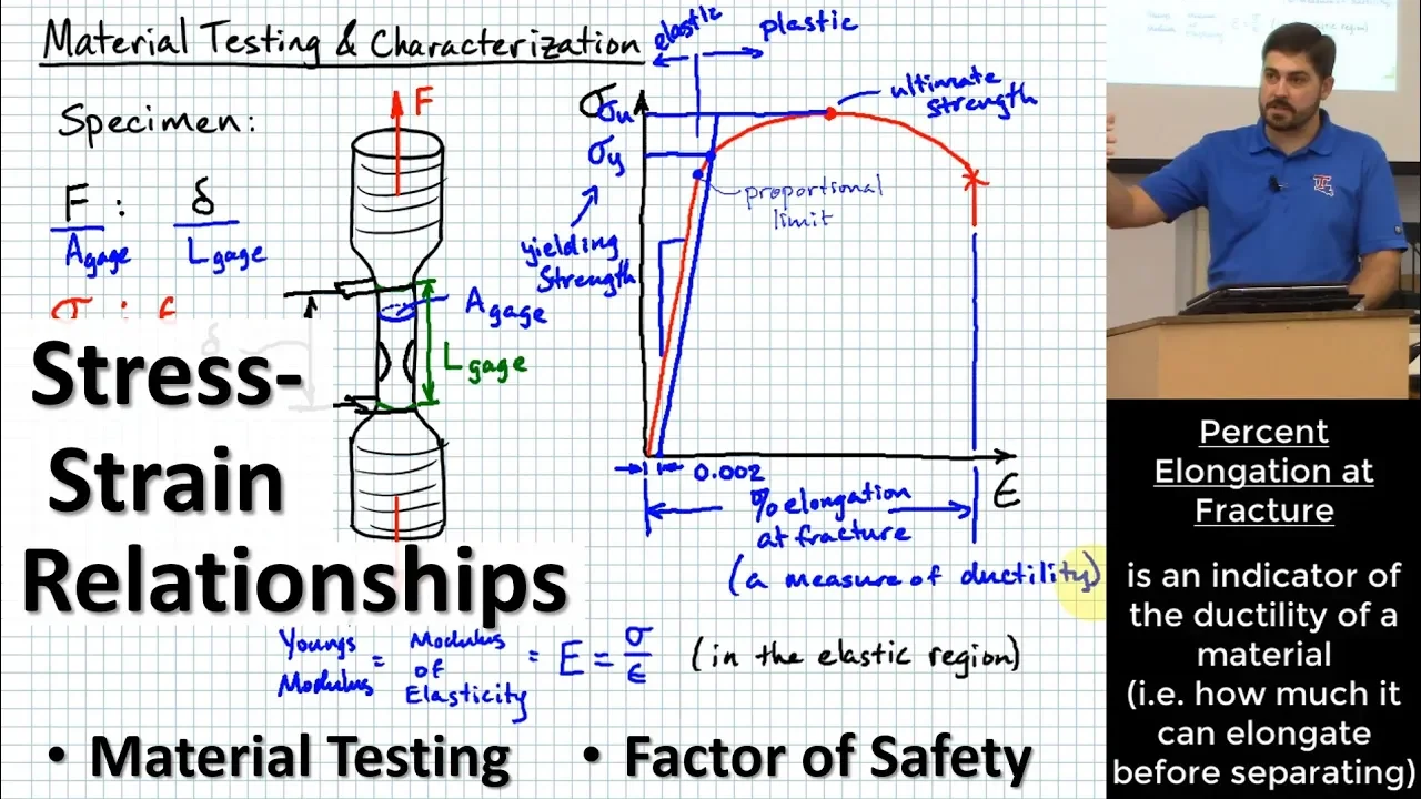
Stress-Strain Relations: Tensile Testing & Material Strength
@TheBomPE
81.2K views•2019-09-16

33:39
How a Student's Question Saved a NYC Skyscraper from Collapse
@veritasium
22.8M views•2025-04-26
Related Study Plans & Knowledge Roadmaps
Structured learning paths in Engineering
engineering
Building Acoustic Levitators: Physics & Arduino
01The Physics of Sound and Standing Waves
02Piezoelectric Transducers and H-Bridge Drivers
03Arduino Programming: Generating 40 kHz Signals
+ 2 more learning modules
14h5 modules
Explore Roadmap
engineering
Building Peltier Cloud Chambers: Particle Tracks
01Cosmic Rays & Cloud Chamber Physics
02Thermoelectric Cooling (TEC) Fundamentals
03Custom Liquid-Cooling Loop Design
+ 2 more learning modules
18h5 modules
Explore Roadmap
engineering
Yagi-Uda Antennas: Modeling, Build & VNA Test
01Introduction to RF and Antenna Fundamentals
02Yagi-Uda Antenna Design Principles
03Antenna Modeling and Simulation in 4NEC2
+ 2 more learning modules
18h5 modules
Explore Roadmap
engineering
ECG Monitor Design: Op-Amps, Filters & Noise
01Electronics & Breadboard Basics
02Op-Amps and Instrumentation Amplifiers
03Bioelectricity and ECG Fundamentals
+ 2 more learning modules
18h5 modules
Explore Roadmap