This video demonstrates practical techniques for mounting limbs to an exoskeleton, including converting shoulder straps into leg loops with quick-release belt clips for seated support, and adapting existing components like child's shin braces to create custom forearm mounts by bolting metal plates and welding socket adapters for secure arm attachment.
Exoskeleton Arm Mount Assembly: Welding and Attachment for Expo Demo
Added:Deep Dive
Basic welding safety and metal fabrication techniques, including the use of MIG or TIG welders to join steel plates.

CHOPPING THE $800 1968 CUTLASS FOR A FULL RESTORATION! MY DADS HOT ROD BUDGET BUILD OLDSMOBILE!
70.5K
This segment demonstrates TIG welding techniques for metal fabrication and repair. The creator explains how to feed MIG wire directly into the TIG weld pool for a smooth, nearly self-forming weld. The segment covers the challenges of TIG welding, including the long time required (about an hour and a half for the section shown) and the need for proper heat control to avoid warping. The creator also demonstrates creating custom metal parts from trailer components, showing how restorers can fabricate solutions when original parts are unavailable.
Click to watch →
![Building a Bumper for my Homemade Flatbed [Steel Flatbed Part 3]](https://i.ytimg.com/vi_webp/QOH8D99zoC4/maxresdefault.webp)
Building a Bumper for my Homemade Flatbed [Steel Flatbed Part 3]
178.8K
This segment covers essential MIG welding techniques for steel fabrication. The builder demonstrates proper welding settings for 8-inch steel plate and 3/16-inch plate: 18.2 volts and 293 inches per minute wire feed speed. Key techniques include welding outside corners to minimize warping, pulling the gun in a straight line without zigzagging, and making long passes before stopping. For vertical down joints, the builder reduces wire feed speed to prevent excessive puddle size while maintaining penetration. The segment also covers hot pass welding with gun manipulation for cosmetic-quality joints.
Click to watch →

The TURBO E36 wagon FIRST START UP!!
141K
MIG welding requires proper torch distance - holding too close causes the arc to wander and creates inconsistent welds. The operator must resist touching the puddle, as this disrupts the welding process. TIG welding requires precise tungsten electrode control and proper filler metal timing. The puddle can be washed and pushed to blend metals, similar to MIG techniques. A sharp tungsten electrode is essential for consistent results.
Click to watch →
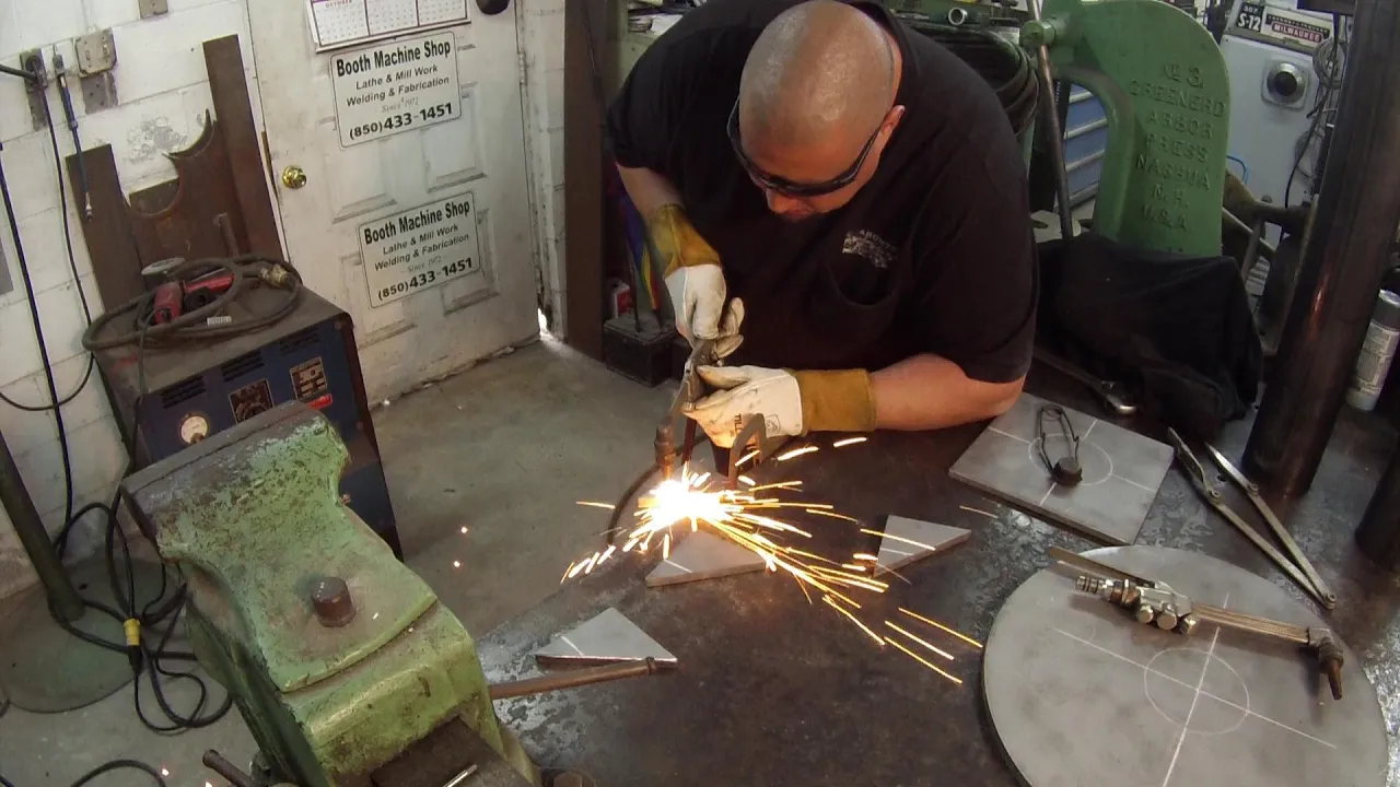
Vise Pedestal Build Part 2
98.4K
This comprehensive segment covers the entire metal fabrication workflow from equipment setup to final weld completion. The process begins with MIG welder preparation including proper wire change technique to prevent tangling, roller selection (smooth vs. serrated) for optimal wire feeding, and wire speed/voltage settings for steel flux core E71T1 welding. Fine-tuning through test welds on scrap material ensures optimal penetration and minimal spatter. The workflow then transitions to plate layout involving center finding, circle tracing for gusset placement, and cutting overhanging gussets. Oxy-acetylene torch cutting is demonstrated with proper tip selection and preheating technique. The final phase covers complete gusset installation including tack welding, alignment checking, squaring, and corner tacking. Full weld bead running demonstrates consistent heat management, distortion control through even spacing and clamping, and proper flux core wire penetration. The process concludes with spatter removal and preparation for assembly onto the main plate.
Click to watch →
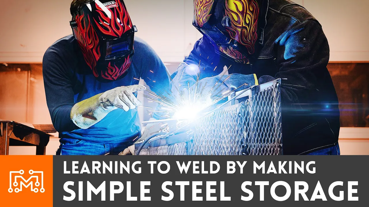
Making Simple Steel Storage while Learning to Weld | I Like To Make Stuff
169.7K
MIG welding joins metal pieces by creating an electric arc between the welding torch and workpiece, melting the metal together while feeding wire filler material through the torch; beginners should start with tack welding to prevent warping, maintain proper wire feed speed and travel speed for consistent welds, and understand that successful welding requires actively moving a molten puddle along the joint rather than simply tracing a line.
Click to watch →
Deep Dive
Fundamental biomechanical principles of the upper human limb, specifically how joint axes align and how force is distributed along the arm.
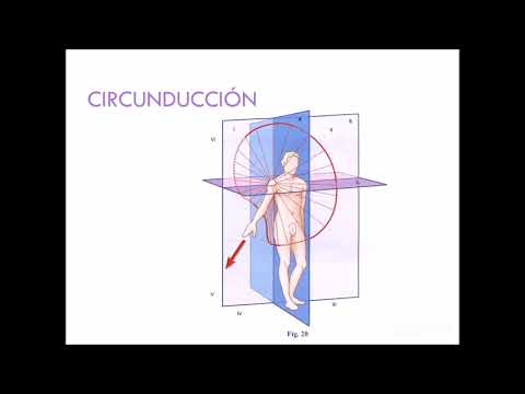
Biomecánica del miembro superior
6.1K
The upper limb exhibits complex biomechanical movements governed by specific articulations and muscle activations: the glenohumeral joint allows three degrees of freedom (flexion/extension, abduction/adduction, and rotation) with the deltoid, pectoralis major, and rotator cuff muscles as primary agonists; the elbow joint permits only flexion and extension (145° each) driven by the biceps brachii and triceps brachii; the forearm undergoes pronation and supination (85-90°) controlled by the pronator teres, pronator quadratus, supinator, and biceps brachii; the wrist enables flexion, extension, abduction, and adduction (5-85° ranges) through the radiocarpal joint; and the hand achieves grasping capability through metacarpophalangeal and interphalangeal joints allowing flexion, extension, and circumduction.
Click to watch →

BDC Volume 1 (Tenth Edition) Introduction
237
The upper and lower limbs share homologous structures: pectoral girdle corresponds to pelvic girdle, shoulder joint to hip joint, arm (humerus) to thigh (femur), elbow to knee, forearm (radius/ulna) to leg (tibia/fibula), wrist to ankle, and carpus/metacarpus/digits to tarsus/metatarsus/digits. The upper limb's functional specializations enable skilled activities: smaller size, freely movable shoulder, carrying angle, supination/pronation for adaptability, two-row carpal arrangement, laterally placed thumb, separated digits, and nail protection. Forces travel through the limb via: hand → wrist joint → radius → interosseous membrane → ulna → elbow joint → humerus → shoulder joint → scapula → coracoclavicular ligament → clavicle → sternoclavicular joint → costoclavicular ligament → axial skeleton.
Click to watch →
Hommage au docteur Kapandji, auteur des ouvrages d'anatomie fonctionnelle de l'appareil locomoteur
4.2K
Joint systems range from single-axis hinges to complex three-axis articulations. Single-axis joints allow rotation around one axis, while two-axis systems enable terminal segment rotation around longitudinal axes. The shoulder exemplifies three-axis joints enabling flexion/extension, rotation, and abduction. The cervical spine demonstrates how oblique joint axes create coupled movements (inclination with rotation and extension), requiring compensation mechanisms at the occipital-cervical junction. The upper limb possesses seven degrees of freedom including elbow flexion/extension, forearm pronation/supination, and wrist movements. The pronation/supination mechanism, inherited from the ichthyostega's limb structure, is present in all vertebrates but not always utilized. The thumb's opposition mechanism involves oblique joint axes and counter-opposition from the fifth metacarpal, enabling complex functional movements.
Click to watch →

Biomechanics Lecture 8 By Dr\ Mahmoud Nasser
1.2K
The upper limb contains four major joints: the shoulder complex (glenohumeral and acromioclavicular joints) and the elbow complex (humeroulnar and humeroradial joints). The humerus has three key orientation angles: internal rotation of 10-18 degrees, glenohumeral angle of 94-98 degrees, and anterior inclination of 30 degrees. The elbow joint functions as a modified hinge joint allowing flexion (0-150 degrees) and extension, with the cubitus varus angle normally ranging from 13-16 degrees. Load transfer through the upper limb occurs primarily through the radius (80%) and ulna (20%), with the annular ligament stabilizing the radial head. The radiocarpal joint allows flexion (0-50 degrees) and extension (0-75 degrees), while the radioulnar joints enable pronation and supination through convex-concave and concave-convex relationships. Joint stability is maintained by both dynamic stabilizers (muscles like triceps and biceps) and static stabilizers (ligaments including the medial and lateral collateral ligaments).
Click to watch →
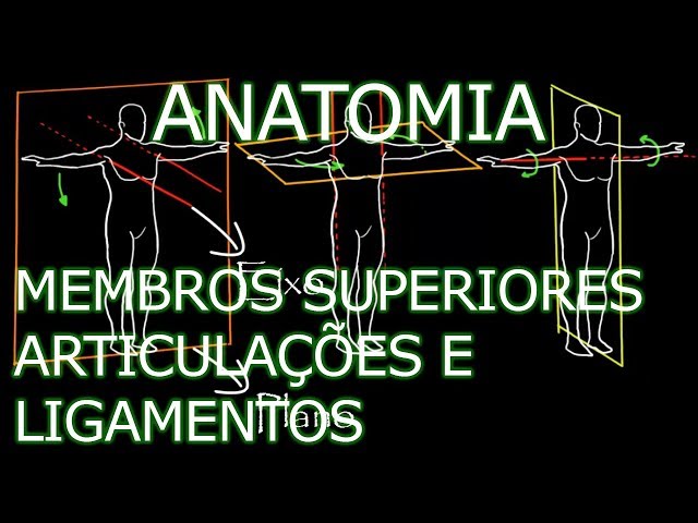
Aula: Anatomia - Membros Superiores - Articulações e Ligamentos | Anatomia Humana Osteomuscular
101.4K
The upper limb contains multiple synovial joints classified by their axes of movement: triaxial joints (like the sternoclavicular and glenohumeral joints) allow movement in three planes, biaxial joints (such as the radiocarpal joint) permit movement in two planes, and monoaxial joints (like the elbow and radioulnar joints) enable movement around a single axis; these joints are stabilized by various ligaments including the costoclavicular, coracoacromial, and transverse scapular ligaments, which provide structural integrity and limit excessive movement.
Click to watch →
Deep Dive
Material properties and selection, understanding the structural behavior of steel versus lightweight plastics like those found in commercial braces.

Metal-to-Plastic Conversions as presented by UL Prospector Sep 2020
459
Four critical material properties govern plastic design: specific gravity (plastics weigh 3-4x less than steel), thermal expansion (filled plastics reduce expansion differences), strength (glass-filled plastics approach steel levels), and stiffness (both unfilled and filled plastics lag behind metals). Effective material selection requires identifying three key requirements (impact, thermal, fatigue) and considering worst-case environmental conditions (temperature extremes, humidity, UV exposure). Data sheets provide screening values only, as real-world properties degrade significantly under combined stressors.
Click to watch →

1 RESISTENCIA DE MATERIALES INTRODUCCION
15.2K
The instructor discusses material properties including elasticity (return to original dimensions after load removal), plasticity (permanent deformation without breaking), ductility (significant deformation before failure with warning), and brittleness (fracture with little deformation without warning). Steel is the most commonly used structural material (over 90% of metal structures), followed by aluminum. Steel advantages include high ductility, simple weldability, easy cutting and bending, and widespread availability. Aluminum advantages include lower weight (one-third of steel's density) and corrosion resistance.
Click to watch →

連続体力学の講義 ~第5回・塑性論と弾塑性力学 その3~
349
Steel braces exhibit different behaviors under tension versus compression. Under tension, they follow the theoretical elastic-plastic stress-strain relationship of metal materials. Under compression, they experience buckling before reaching yield stress, causing sudden load reduction. Plastic hinges form at the center due to geometric instability. After buckling, the brace enters a post-buckling state where load recovery is slow during shape reversal. While individual material points follow theoretical stress-strain rules, overall member behavior is governed by geometric factors like buckling, making structural behavior distinct from material properties.
Click to watch →
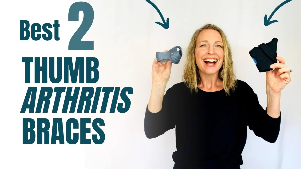
Best Thumb Arthritis Braces (PRODUCT REVIEW)
95K
The Push MetaGrip uses polyurethane material with an embedded metal piece for thumb CMC support, while the Comfort Cool uses neoprene for breathability. Both materials are latex-free and machine-washable. Neoprene provides better breathability for summer heat, while polyurethane offers more rigid structural support.
Click to watch →

HOW TO SELECT THE RIGHT MATERIAL DURING DESIGN
214
Thermosetting plastics (melamine, urea formaldehyde, phenolics, epoxies) cannot be reused once cured; thermoplastics (polypropylene, HDPE, ABS, PVC, polycarbonate, nylon) can be remolded. Plastic advantages include lightweight, low cost, recyclability, excellent finish, easy molding, and color variety for aesthetics. Limitations include lower strength, unsuitability for hot conditions, limited accuracy, disposal challenges, and inability to produce very complex parts beyond certain limits. Material selection matrix: for accuracy—steel is best; for cost—plastic is most economical; for aesthetic finish—aluminum provides best results. Cost ranges: mild steel ₹60-70/kg, cast iron ₹70-80/kg, aluminum ₹250/kg, copper ₹300-350/kg. These cost variations significantly impact material selection decisions.
Click to watch →
Deep Dive
Basic mechanical design and blueprint reading, including how to measure, mark, and cut custom metal brackets.
MY FIRST SCANIA FABRICATION JOB… FROM HOLLAND!
91K
When fabricating custom brackets, accurate measurement and marking are essential. The presenter demonstrates measuring from reference points (like a straight edge) to determine the required dimensions for each bracket. The measurements taken include 52, 95, 33, and 75 millimeters. These measurements are then transferred to the material to be fabricated, ensuring the brackets will fit correctly when installed.
Click to watch →
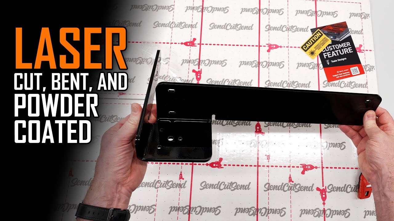
How I Create Gorgeous Bent Steel Parts with Fusion and SendCutSend
47.5K
Accurate bracket design requires precise measurement of existing components. Using a metric tape measure, critical dimensions were captured including overall width (460mm), vertical spacing between handle holes (54mm), horizontal spacing (380mm), and positions relative to edges. The designer measured the folded sheet metal lip and flange to ensure the new bracket wouldn't interfere with existing features. In Fusion 360, these measurements were used to create a sketch on the toolbox surface, projecting geometry points to establish the base flange location. A centered rectangle was drawn using diagonal construction lines to ensure proper alignment, with 5mm reveal maintained around the edges to accommodate the handle flange.
Click to watch →

Mechanical Assembly Grade 12 from The Study Pack
857
This segment demonstrates how to draw the base plate and brackets systematically. The instructor shows how to measure dimensions (120mm width, 15mm height, 15mm spacing), draw light construction lines first, and then solidify the final lines. The cutting plane concept is explained - when a cutting plane passes through a component, it appears solid without hidden detail lines. Brackets are drawn using symmetry, with measurements of 30mm length and 100mm height.
Click to watch →

1970 Cougar Restoration Part 2
615
Fabricating custom metal brackets involves a systematic process: marking the halfway point on metal pieces to establish bend locations, measuring from center lines to determine bend positions (e.g., 3/4 inch), marking new lines at measured distances, and measuring 1 inch from center lines on each side to establish hole locations 4 inches apart. A punch is then used to create dimples at marked points, serving as centering spots for drill bits. For 6-inch plates, the center is marked at 3 inches. This precise measurement and marking ensures accurate hole placement for mounting hardware.
Click to watch →

Recaro seats in my Honda Civic Wagon using OEM seat rails! then this happened...
379
Creating custom metal brackets involves a systematic process: (1) marking required holes and cut lines, (2) drilling holes to specified sizes, (3) filing holes to create clean edges, (4) cutting excess material using a grinding wheel, and (5) finishing by rounding edges and cleaning surfaces. The process requires careful measurement, attention to detail, and proper tool selection to ensure the bracket functions correctly and safely.
Click to watch →
Prerequisite Knowledge
- Concept 01Basic welding safety and metal fabrication techniques, including the use of MIG or TIG welders to join steel plates.
- Concept 02Fundamental biomechanical principles of the upper human limb, specifically how joint axes align and how force is distributed along the arm.
- Concept 03Material properties and selection, understanding the structural behavior of steel versus lightweight plastics like those found in commercial braces.
- Concept 04Basic mechanical design and blueprint reading, including how to measure, mark, and cut custom metal brackets.
Subsequent Learning
- Step 01Integration of electromechanical actuators (such as motors or linear actuators) and sensors onto the physical arm mount.
- Step 02Advanced human-robot interaction (HRI) design, focusing on ergonomics, pressure point distribution, and custom padding to prevent user injury.
- Step 03Finite Element Analysis (FEA) to computationally test the weld joints and structural integrity under dynamic loading conditions.
- Step 04System testing and safety certification protocols for wearable robotic devices prepared for public exhibition and demonstrations.
Leg Support
Arm Mount
Build Completed
Leg Support
0:00Playing Section
- 1
Creates leg loops from shoulder straps for sitting support.
- 2
Adds quick-release belt clips to secure the user to the exoskeleton.
Soft Exosuits and Compliant Robotics Paradigm
While rigid steel frames provide structural strength, modern biomechanical engineering increasingly favors soft exosuits and compliant design over rigid hardware. Rigid steel structures impose significant weight penalties and present severe risks of joint misalignment, where the robotic joint does not perfectly align with the human anatomical joint, potentially causing shear stress and musculoskeletal injury. In contrast, soft exosuits utilize flexible textiles, elastomers, and cable-driven actuators to distribute forces naturally across the body. This alternative paradigm prioritizes user safety, ergonomics, and natural range of motion over heavy, rigid load-bearing frames.
Deep Dive
Integration of electromechanical actuators (such as motors or linear actuators) and sensors onto the physical arm mount.

final assembly video (6 of 6)
139
Motor arms should be attached to the motor assembly, and sensor arms attach at the end of the structure. Sensor arms allow for adding sensors later. If arms are placed on the wrong side, they can be switched by simply moving them to the correct position. The axle may need rotation to lock components in place.
Click to watch →

Thomson / Lineární aktuátory - náhrada za hydraulické válce / BIBUS
618
Linear actuators controlled by electricity offer significant integration advantages over hydraulic systems. It is much easier to add feedback systems and integrate them with readily available microprocessors, which is helping to spur the growth of electromechanical linear actuator technology.
Click to watch →
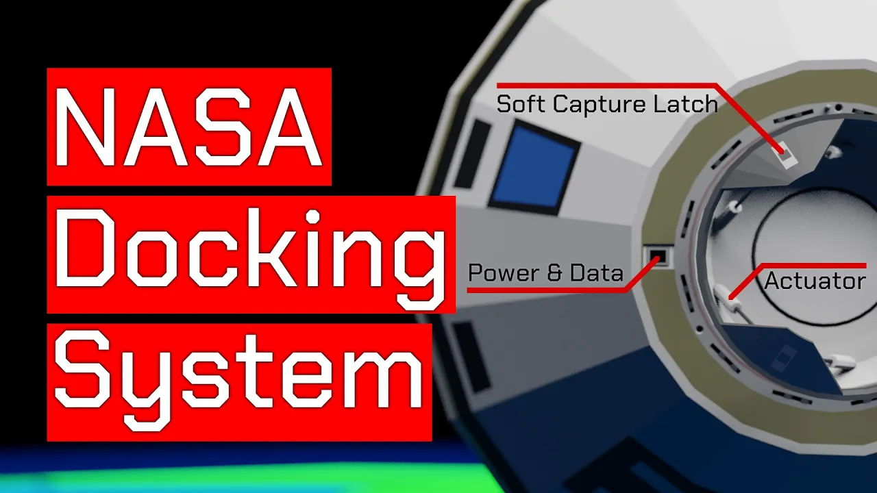
How the NASA Docking System Works
335.7K
An electromechanical linear actuator is essentially a threaded rod that can be extended and retracted using an electric motor. The motor engages with the threaded rod via a threaded sleeve. By mounting the active soft capture ring on six linear actuators, the system can vary the extended length of each actuator to move the soft capture ring with six degrees of freedom—three axes of rotation and three axes of translation.
Click to watch →
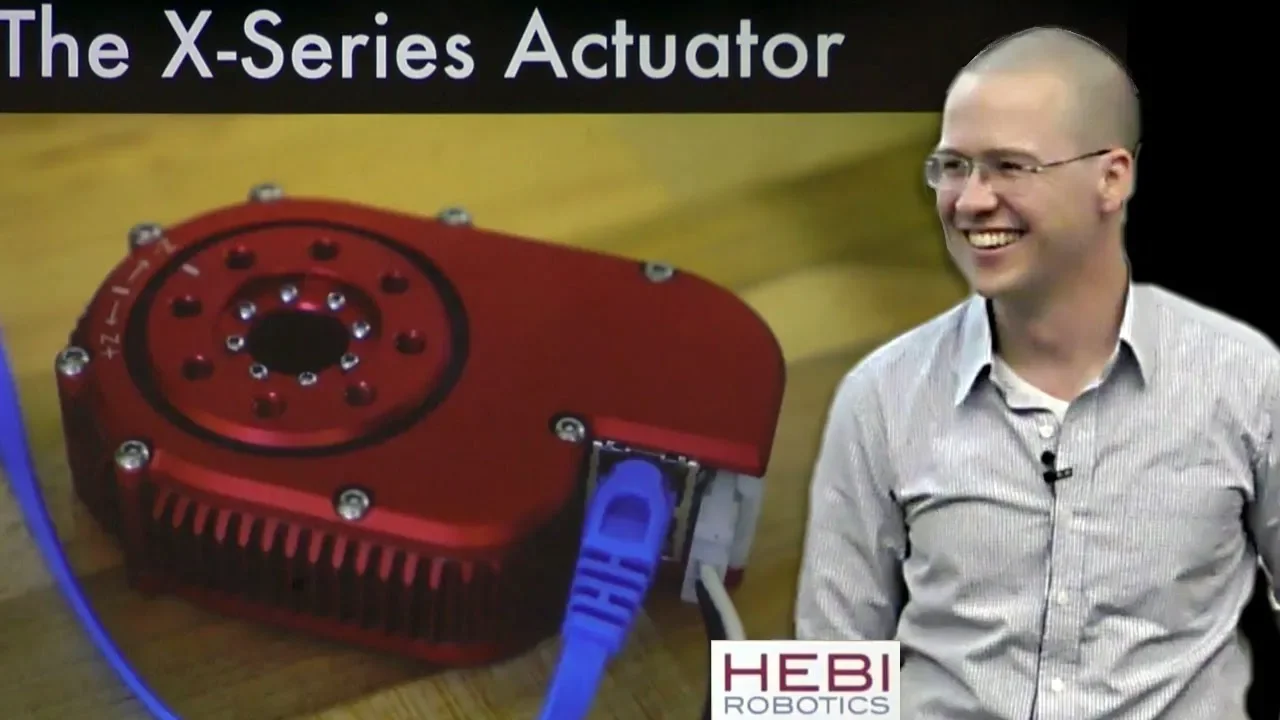
RI Seminar : Dave Rollinson : Building a Force-Controlled Actuator (Company)
4.6K
An actuator is a mechanical device that converts energy into motion. For electric motors, the core components include: (1) Electric motor - provides rotational force; (2) Transmission/gears - necessary because motors are high-speed low-torque while applications require high-force low-speed; (3) Sensors - required for closed-loop control; (4) Motor controllers - manage power delivery; (5) Communication interfaces - enable network connectivity; (6) Mounting hardware; (7) APIs and software tools - essential for coordinating multiple actuators in complex systems like arms or legs.
Click to watch →

S3 OrthoAgility® Shoulder CPM
17.8K
To mount the actuator: (1) Loosen the locking lever on the mounting bracket, (2) Depress the safety pin on the turret arm, (3) Slide the actuator onto the arm while supporting its weight, (4) Turn the actuator so it is parallel to the armrest. This ensures proper attachment and alignment for patient treatment.
Click to watch →
Deep Dive
Advanced human-robot interaction (HRI) design, focusing on ergonomics, pressure point distribution, and custom padding to prevent user injury.

HRC Robot Safety Requirements
1K
Collaborative robot safety relies on controlling exposure to pain thresholds established through university studies of diverse populations across ages, genders, and employment types. Two contact types were analyzed: quasi-static events lasting greater than half a second (crushing/trapping scenarios) and transient contacts with impulse peaks under half a second (bumping incidents). Fifteen body regions and twenty-nine specific areas were studied to establish maximum acceptable pressure and force values. Contact pressure calculation involves dividing theoretical force by contact surface area (e.g., 150N over 70mm² yields 214N/cm²). Risk reduction measures include padding, compliant mechanical designs with springs, avoiding sharp edges, minimum contact surface area of 30mm², tactile coverings on robot exteriors, and proper feature radii. Transient contact analysis requires calculating effective robot mass (moving mass plus payload) and consulting energy flux graphs to determine speed limits for different body regions.
Click to watch →

$70 vs $700 Motorcycle Helmet | Is it worth the price?
494.2K
Quality helmet interior padding should evenly distribute pressure across the entire head surface, creating a secure and comfortable fit. Poorly designed padding creates pressure points on specific areas of the head, such as the forehead, leading to discomfort during extended wear. A spacious interior that fails to fully contain the head results in an unsafe feeling and potential pressure points, even if the rider has a naturally larger head size.
Click to watch →
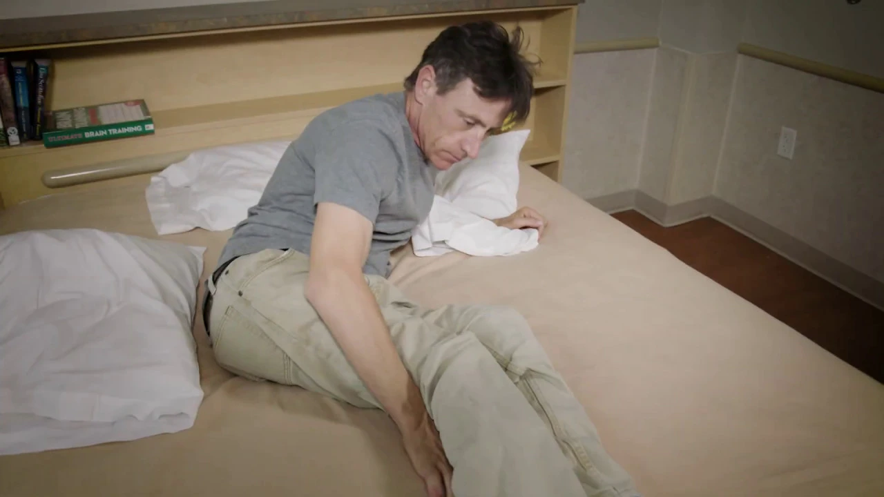
Pressure Injury Prevention: Padding and Positioning
16.7K
Pressure injuries develop when bony areas (head, ears, shoulder blades, elbows, hips, tailbone, knees, ankles, heels, and toes) experience prolonged pressure, with both overweight and underweight individuals facing elevated risks; prevention requires proper padding using materials like pillows, foam pads, wedges, and specialized surfaces, combined with strategic positioning (avoiding direct tailbone pressure when lying on back or side) and adherence to a regular turning schedule to relieve pressure on vulnerable skin areas.
Click to watch →
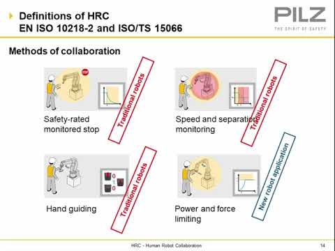
Human Robot Collaboration Essentials - Risk Assessment and Validation
1.5K
Contact pressure measurement uses pressure-sensitive film applied over force gauges. When the robot strikes the force gauge, the contact surfaces create pressure against the film. The film is analyzed through scanning and software to determine actual contact pressures. This allows simultaneous measurement of force and pressure at the same contact point. Analysis reveals whether contact pressures are within limits and identifies any sharp edges requiring padding.
Click to watch →

SARAH: connecter et interagir avec l'Internet des Objets au quotidien
4.5K
The presenter discusses ergonomic considerations in human-robot interaction, referencing the film 'Her' and robots like Romeo (1.2m tall). The challenge is creating robots that feel subordinate to humans (not overwhelming) while still being capable of helping (like assisting someone who has fallen). This reflects broader ergonomic challenges in designing connected objects that enhance rather than complicate human interaction. The desire for physical embodiment (animatronic faces responding to voice) represents a trend toward moving from abstract interfaces to physical entities that can interact with humans in natural ways.
Click to watch →
Deep Dive
Finite Element Analysis (FEA) to computationally test the weld joints and structural integrity under dynamic loading conditions.

Dynamic Welding
309
This section covers the core principles of analyzing welded joints under dynamic loading. Key concepts include: (1) Dynamic stress parameters—stress range (Δσ), alternating stress (σa), mean stress (σm), stress ratio (R), and amplitude ratio—all derived from maximum and minimum stress values; (2) Unique behavior of welds where mean stress has negligible effect on fatigue strength, unlike unwelded materials; (3) AISC-established weld geometry categories (A-F) that classify fatigue resistance levels; (4) Two-standard deviation method for determining fatigue strength with 95% confidence; (5) Why correction factors for surface finish and size are unnecessary for weld fatigue testing. These fundamentals form the basis for all subsequent weld design calculations.
Click to watch →

Webcast de Simulación dinamica y Elementos Finitos en Autodesk Inventor
10.3K
Finite Element Analysis (FEA) is a computational method that predicts how objects react to real-world forces by dividing complex structures into finite elements connected by nodes, where each element's behavior is calculated using mathematical equations based on Hooke's Law; this method requires assumptions of linear behavior, static loads, small deformations, and no temperature effects, and is used in Autodesk Inventor Professional to validate structural integrity through dynamic simulation followed by static analysis with mesh convergence verification.
Click to watch →

What is Finite Element Analysis? FEA explained for beginners
272.6K
Finite Element Analysis (FEA) is a numerical engineering method that solves complex problems by dividing them into smaller, simpler parts called finite elements, which are then analyzed individually and assembled to predict how real-world objects behave under various conditions; this technique uses geometry files and material properties to create virtual models that can simulate physical phenomena like car crashes or structural stresses more efficiently and cost-effectively than physical testing.
Click to watch →

Abaqus Fracture and Failure Simulation : The Only Tutorial You’ll Ever Need
2.5K
This tutorial demonstrates simulating welded joints in Abaqus by creating separate material definitions for base metal and weld metal. Both materials share similar density and elastic modulus but exhibit different plasticity curves and damage evolution characteristics. Base metal typically shows lower ductility than weld metal. The workflow includes: (1) Creating base metal geometry with weld feature partitions, (2) Defining distinct material properties for each region, (3) Assigning appropriate sections to base and weld regions, (4) Setting up dynamic explicit analysis with proper constraints and loads, (5) Running the simulation to observe how weld properties affect stress distribution and failure location. This approach enables realistic prediction of how welded joints perform under tensile loading.
Click to watch →
SOLIDWORKS Simulation Webinar | Panshul Technologies
114
This section covers dynamic analysis and weldment evaluation capabilities. Static study serves as the foundation for all simulation types, from which users can create nonlinear static, nonlinear dynamic, and linear dynamic analyses. Transient analysis simulates time-dependent loading such as earthquakes by defining base excitation (accelerometer data) with time period, amplitude, and G values. Results show increased stress values and displacement compared to static analysis. Response spectrum analysis provides additional information about acceleration values at different frequencies. Weldment analysis automatically identifies connection points between structural members and bifurcates between fabricated members (welded geometry) and structural members (standard beams). Users define bonded connections, fixed faces, and roller sliders. Results show maximum stress in fabricated and structural members along with displacement values. Beam diagrams provide visual representation of internal forces. Factor of safety visualization uses color-coded plots with isoclines to highlight regions below safety limits, enabling targeted design improvements.
Click to watch →
Deep Dive
System testing and safety certification protocols for wearable robotic devices prepared for public exhibition and demonstrations.

Oregon-made walking, humanoid robot testing package delivery from curb to your doorstep
34.2K
For robots to be accepted in society, they must meet three critical safety requirements: they must be completely safe outside of peripheral vision, they must feel completely safe to people around them, and they must be comfortable to have around in daily environments. These requirements are essential for public acceptance of robotic technology.
Click to watch →

FULL Episod Baru Upin & Ipin Musim 17 - Neo Santara Wirabot | Upin Ipin Terbaru 2023
5.9M
Robots that are not yet fully tested or certified for safety cannot be deployed for public use. Safety inspections are necessary before robots can be used to protect communities.
Click to watch →
![[기업] 삼성 웨어러블 보행보조 로봇 '젬스', 국제표준 인증 받아 / YTN](https://i.ytimg.com/vi_webp/3OUXejpkkXw/maxresdefault.webp)
[기업] 삼성 웨어러블 보행보조 로봇 '젬스', 국제표준 인증 받아 / YTN
8.5K
The Korean Robot Industry Promotion Agency has granted international standard certification to Samsung's wearable walking assistance robot. This certification validates that the robot meets established international safety standards, ensuring it is safe for use and meets global quality benchmarks.
Click to watch →

協調安全ロボットシステムセミナーVol.2
1.1K
Robot safety is verified through performance level assessment (such as PLd) and compliance with international safety standards including ISO 10218 (Part 1 and Part 2) for robot safety requirements and ISO 13849 (Part 1) for control system safety design. Manufacturers must demonstrate that their robots meet these standards to be certified as safe.
Click to watch →

핵심규제 합리화 전략회의에서 한국의 로봇 산업성장이 늦은 이유는 규제 때문에!#KTV # 로봇 #규제완화
191.4K
When robots are legally recognized as people, a safety certification system is established for them. This system requires robots to pass approximately 14-15 different safety tests. Only robots that successfully pass all these tests receive legal recognition as autonomous entities. This certification process creates a formal pathway for robots to operate legally in society.
Click to watch →
Leg Support
Arm Mount
Build Completed
Leg Support
0:00- 1
Creates leg loops from shoulder straps for sitting support.
- 2
Adds quick-release belt clips to secure the user to the exoskeleton.
Soft Exosuits and Compliant Robotics Paradigm
While rigid steel frames provide structural strength, modern biomechanical engineering increasingly favors soft exosuits and compliant design over rigid hardware. Rigid steel structures impose significant weight penalties and present severe risks of joint misalignment, where the robotic joint does not perfectly align with the human anatomical joint, potentially causing shear stress and musculoskeletal injury. In contrast, soft exosuits utilize flexible textiles, elastomers, and cable-driven actuators to distribute forces naturally across the body. This alternative paradigm prioritizes user safety, ergonomics, and natural range of motion over heavy, rigid load-bearing frames.
Basic welding safety and metal fabrication techniques, including the use of MIG or TIG welders to join steel plates.
Fundamental biomechanical principles of the upper human limb, specifically how joint axes align and how force is distributed along the arm.
Material properties and selection, understanding the structural behavior of steel versus lightweight plastics like those found in commercial braces.
Basic mechanical design and blueprint reading, including how to measure, mark, and cut custom metal brackets.
Integration of electromechanical actuators (such as motors or linear actuators) and sensors onto the physical arm mount.
Advanced human-robot interaction (HRI) design, focusing on ergonomics, pressure point distribution, and custom padding to prevent user injury.
Finite Element Analysis (FEA) to computationally test the weld joints and structural integrity under dynamic loading conditions.
System testing and safety certification protocols for wearable robotic devices prepared for public exhibition and demonstrations.
151.6K views1.8Klikes4:52@hacksmithOriginal Release: 2016-04-30
[Music] all right so we're going to use some shoulder straps to create some leg Loops so that I can actually be supported from the exoskeleton so we lock the limbs I can actually sit and the legs will hold me up so we're going to just have to modify these a little [Music] bit so we'll start by adding a quick release belt [Music] clip there we go so I'll go around my leg and then this will attach to either the hip joint or the uh upper portion of the leg of the [Music] [Music] exoskeleton all right so we've got the shoulder joint here and then this is actually I guess the bicep part of the arm and we're just going to going to weld that in place it'll still be modular so we have to pin it here but let's get [Music] welding all right so right now I'm working on the arm mount to attach my arm to the exoskeleton arm and we actually found that a child's Shin brace actually fits perfectly on my forearm so what I'm doing right now is making a small piece of Steel that will actually bolt to this and then we're going to weld another one of these socket adapters on here to attach the arm so let's do [Music] that all right so I got the metal plate attached to the shinard now now I just need to weld one of these guys right on top like [Music] [Music] that and there we go see that guy clips into [Music] here hey guys so we wanted to make that video a bit longer and we have all the footage to do so we just don't have time to edit together right now because we're crazy busy preparing for the Expo we're leaving today uh the Expo is tomorrow May 1st at uh the Sheran Center in Toronto if you're in the area come see me we're going to pick up a DeLorean with the exos skeleton anyway stay tuned as soon as we get back we'll get the rest of the footage edited and you'll be able to see the EXO and all its Glory that being said we're also going to try and live stream the GTA Expo we just don't know if we'll be able to it depends on the internet connection there but don't worry if you can't make it we're also going to film it and we'll be posting that next week as well so thanks for watching and stay tuned for the next [Music] update [Music] yeah
Up Next
4:02
Reverse Osmosis Process Explained: How It Purifies Water
@SydneyWaterTV
2.9M views•2013-10-29

30:32
Ultrasonic Transducers: Resonant Frequency Measurement and Horn Design
@imajeenyus42
229.9K views•2017-02-22

54:16
Polymer Environmental Degradation: Mechanisms & Stabilization
@iit
1.8K views•2012-07-10

33:39
How a Student's Question Saved a NYC Skyscraper from Collapse
@veritasium
22.8M views•2025-04-26
Related Study Plans & Knowledge Roadmaps
Structured learning paths in Engineering
engineering
Building Acoustic Levitators: Physics & Arduino
01The Physics of Sound and Standing Waves
02Piezoelectric Transducers and H-Bridge Drivers
03Arduino Programming: Generating 40 kHz Signals
+ 2 more learning modules
14h5 modules
Explore Roadmap
engineering
Building Peltier Cloud Chambers: Particle Tracks
01Cosmic Rays & Cloud Chamber Physics
02Thermoelectric Cooling (TEC) Fundamentals
03Custom Liquid-Cooling Loop Design
+ 2 more learning modules
18h5 modules
Explore Roadmap
engineering
Yagi-Uda Antennas: Modeling, Build & VNA Test
01Introduction to RF and Antenna Fundamentals
02Yagi-Uda Antenna Design Principles
03Antenna Modeling and Simulation in 4NEC2
+ 2 more learning modules
18h5 modules
Explore Roadmap
engineering
ECG Monitor Design: Op-Amps, Filters & Noise
01Electronics & Breadboard Basics
02Op-Amps and Instrumentation Amplifiers
03Bioelectricity and ECG Fundamentals
+ 2 more learning modules
18h5 modules
Explore Roadmap