This video demonstrates how to control a high torque servo motor (ASME-03) using Arduino Uno to achieve precise 0 to 180-degree rotation, with the presenter explaining the programming approach and confirming successful operation of the system.
High Torque Servo Control with Arduino Uno and ASME-03: 0-180 Degrees
Added:Deep Dive
Basic Arduino programming and familiarity with the Arduino IDE, including uploading sketches and utilizing standard libraries like 'Servo.h'.

CARA CODING PEMBUATAN LAMPU PANGGUNG (MOVING HEAD) MENGGUNAKAN ARDUINO IDE || PEMULA PASTI BISA
6K
This comprehensive tutorial covers the complete Arduino programming workflow for controlling servo motors. The process begins with installing Arduino IDE by downloading from the official website, extracting the file, and running the installer. After installation, users connect the Arduino board via USB cable and select the appropriate board type (Uno, Nano) and COM port in the IDE. The Servo library is installed through Sketch > Include Library > Manage Libraries. Users learn to declare servo variables with naming conventions (servo1Bawah, servo1Atas), configure pins using attach(), and control servo angles (0-180 degrees). Multiple servos can be controlled by following the naming pattern. Speed control uses setSpeed() with multiple values (speed1, speed2, speed3) to create varied movements. The move() function programs servo sequences with target position, speed, and delay (measured in milliseconds). Finally, code is uploaded to the Arduino by clicking the upload button and selecting the correct COM port.
Click to watch →
![GRUA con ARDUINO || PROYECTO con servomotores || Para principiantes [Explicado paso a paso]](https://i.ytimg.com/vi_webp/B2lwaLmHDEI/maxresdefault.webp)
GRUA con ARDUINO || PROYECTO con servomotores || Para principiantes [Explicado paso a paso]
1.5M
To use servo motors with Arduino, the Servo library must be installed. In the Arduino IDE, go to Sketch > Include Library > Manage Libraries. Search for 'servo' in the search bar, find the 'Servo' library, and click Install. This library provides the functions necessary to control servo motors from the Arduino board.
Click to watch →

Basic concept of Arduino in Hindi | Arduino tutorials for beginners part #1
1.4M
Arduino IDE is free software available for all operating systems (Windows, Mac, Linux). Download from Arduino website by searching 'Arduino IDE' and clicking the first official option. After installation, the desktop icon launches the IDE containing: File menu (New, Open, Save), Examples menu with pre-written code templates (LED blinking, LCD interfacing, sensors), Sketch menu with Include Library for sensor commands, and Tools menu for board and port selection. For successful programming, select the correct board (Uno, Mega, Nano, Mini) and the connected serial port (e.g., COM3). The Upload button transfers programs to Arduino, enabling control of connected components like the built-in LED on pin 13.
Click to watch →

Aproveite a quarentena! Aprenda como criar um programa no Arduino
12.7K
After including a library, you must declare its use using the library's name (e.g., Servo). Library names are case-sensitive (Servo vs servo are different). You can create instances of library objects (like Servo servo1) and give them custom names for your project. The attach() command specifies which pin a servo motor is connected to, and must be placed in setup() since pin assignments should only be done once when the Arduino starts. The write() command sets the servo motor position to a specific angle, typically ranging from 0 to 180 degrees for standard servo motors.
Click to watch →

Arduino Coding for Beginners | How to Program an Arduino?
591.5K
Arduino IDE (Integrated Development Environment) is a free software used for writing, compiling, and uploading code to Arduino boards. It functions as a lightweight text editor where you write your code. The code written inside Arduino IDE is called an Arduino sketch. Arduino programming uses a language similar to C++ and is designed to be very easy to learn. The code is first compiled into machine-readable language and then uploaded to the Arduino board.
Click to watch →
Deep Dive
Fundamental concepts of Pulse Width Modulation (PWM) and how duty cycles translate to absolute positioning (0 to 180 degrees) in servo motors.

Raspberry Pi Pico en Español || Servomotor y Ciclo For || Micropython 2
26.1K
The internal circuit of a servomotor interprets input signals lasting approximately 20 milliseconds. The position depends on the pulse width within this window: 0.5ms high state positions at 0 degrees, 1.5ms at 90 degrees, and 2.5ms at 180 degrees. PWM (Pulse Width Modulation) controls pulse width. The PWM frequency is set to 50 Hz, creating 20-millisecond pulses. Two methods control pulse width: duty_ns (measured in nanoseconds) and duty_cycle (16-bit resolution, 65,536 values). Values of 0 represent completely low state, while 65,535 represents completely high state. Specific duty cycle values: 500ns for 0 degrees, 1500ns for 90 degrees, and 2500ns for 180 degrees.
Click to watch →

Tiny Techies Module 2 Menengah - Terengganu
114
This section covers servo motor control using PWM (Pulse Width Modulation). Servo motors are used for precise angular control in applications like automatic gates and robotic arms. They have three wires: power (brown/red), ground (black), and signal (green/yellow/orange). The power wire connects to 3.3V or 5V, ground to ground, and signal to a microcontroller pin (e.g., D15). To control servos, you must import both 'pin' and 'PWM' from the machine module. Servo motors use PWM signals with a duty cycle range of 25 to 125, where 25 corresponds to 0 degrees and 125 corresponds to 180 degrees. The duty cycle determines how long the signal is 'on' within each cycle, controlling the servo's position. The duty cycle formula is: duty = min_duty + (angle / 180) * (max_duty - min_duty). For a servo with min_duty=25 and max_duty=125, this converts angles (0-180 degrees) to duty cycle values. A duty cycle of 50 means the motor receives power for 50ms, causing limited movement. A duty cycle of 100 means longer power duration, causing more movement. The duty cycle repeats continuously as the servo moves through different positions.
Click to watch →
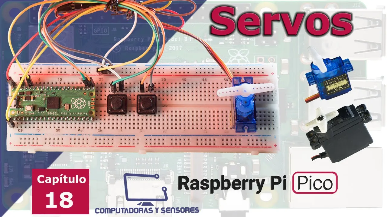
Todo sobre Servos y Raspberry Pi Pico. PWM, Duty Cycle, códigos en Micropython para servomotor.
10.5K
A servo is an electromechanical device that rotates an axis with high precision, consisting of a DC motor, electronic control circuit, position sensor, gears, and housing. Servos are classified by weight: micro (3-10g), mini (11-25g), standard (25-60g), and large (over 60g). PWM (Pulse Width Modulation) controls servos using two states: high (0.3V) and low (0V). Duty cycle represents the percentage of time the signal remains high, ranging from 0% to 100%. Standard 180-degree servos operate with duty cycles between 2% (0 degrees) and 12% (180 degrees). Frequency is measured in Hertz (typically 50 Hz for servos), and period is the reciprocal (20 milliseconds for 50 Hz).
Click to watch →

دورة التصميم الالكتروني المحترف:: 41- تصميم دائرة بوظائف متسلسلة لمصنع بواسطة 555
9.5K
A servo motor is a small DC motor with three terminals: positive (5V), ground, and a signal terminal. It is controlled using Pulse Width Modulation (PWM), a square wave signal where the 'on' portion width determines the motor's position. The PWM pulse width ranges from 0.5ms to 2.5ms with a 20ms total period. At 1.5ms, the motor is at 0 degrees (center); at 2ms, it moves to 90 degrees; at 1ms, it moves to -90 degrees. Servo motors come in two types: continuous rotation (direction controlled by PWM duty cycle) and position control (angle controlled by PWM pulse width).
Click to watch →

Raspberry Pi Servo Motor Control
415.8K
This video explains how to control SG90 servo motors using a Raspberry Pi by generating Pulse Width Modulation (PWM) signals through Python programming; servos differ from regular motors in that they provide precise angular position control (0-180 degrees) via a feedback mechanism, where the angle is determined by the duty cycle of a 50Hz PWM signal (2% duty cycle = 0°, 12% duty cycle = 180°), and the Raspberry Pi's GPIO pins can generate these signals to control one or more servos simultaneously.
Click to watch →
Deep Dive
Understanding the necessity of external power supplies for high-torque, high-current motors (like the ASME-03) to prevent damaging the Arduino Uno board.
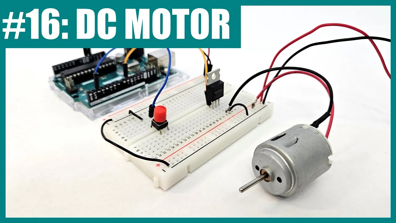
Control a DC Motor with Arduino (Lesson #16)
453.1K
Motors require external power supplies because they draw much more current than the Arduino can provide. Connect the motor's positive terminal to the external battery pack's positive bus, and the motor's negative terminal to the transistor's Drain pin. The transistor then allows current to flow from the battery through the motor, through the transistor's Drain and Source pins, and back to ground. This keeps all high-current paths separate from the Arduino's low-current control circuit.
Click to watch →
Curso de Arduino Bernardo T. Cap 57. Metodo DEFINITIVO para alimentar componentes de alto consumo
724
High-power DC motors like the 775 series require significantly more voltage and current than standard Arduino projects. These motors cannot be powered by the Arduino's 5V output or even by 7.5V from two 18650 batteries. They require external power sources because passing such high currents through the microcontroller would cause immediate damage. The key principle is that high-power components must be powered independently from the microcontroller to prevent system failure.
Click to watch →
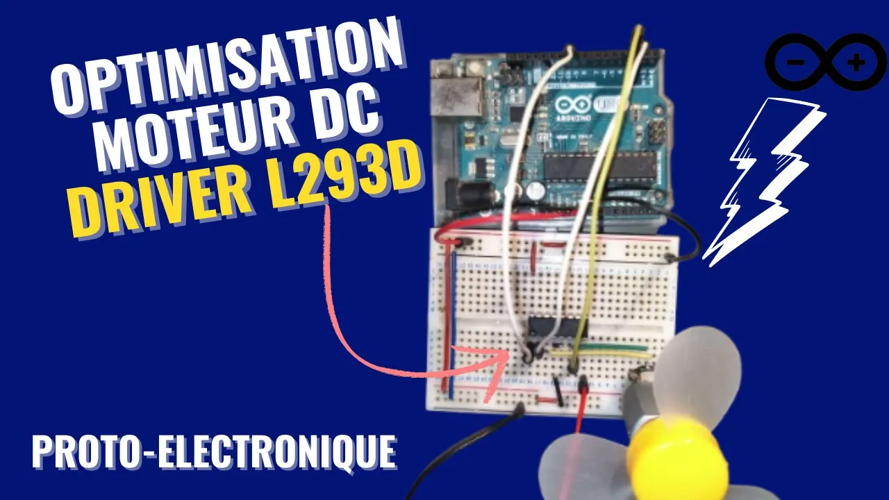
Comment contrôler un moteur DC avec un L293D et une boucle FOR : Tutoriel DIY Facile
887
When a motor requires more current than the Arduino can provide, an external power supply must be connected to the L293D's Vcc2 pin (pin 8). The external power source (such as a battery or power adapter) provides the necessary current for motor operation, while the Arduino only provides control signals. The negative terminal of the external power supply connects to the circuit's common ground. This separation prevents the Arduino from being damaged by motor startup currents while ensuring the motor receives adequate power.
Click to watch →

Fuente de alimentación externa para Arduino.
90.1K
Arduino boards (UNO, MEGA, LEONARDO, DUE) require an external power supply of 12V DC with a current rating between 0.75A and 1.5A to operate safely; using a power supply with higher amperage can damage the board, while the voltage regulator ensures proper voltage distribution to the pinout for stable 24-hour operation.
Click to watch →
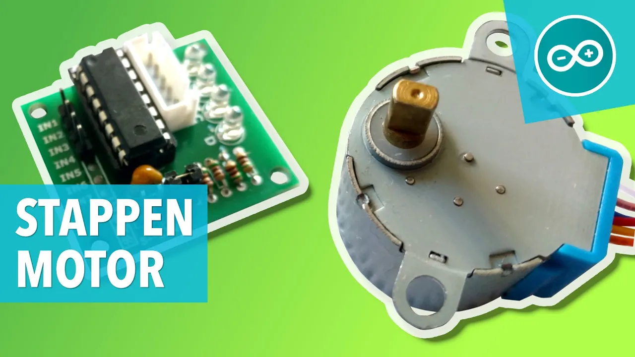
🇳🇱 28BYJ-48 STAPPENMOTOR MET ULN2003 DRIVER - Arduino les #14
46.1K
Motor driver boards require an external power supply because stepper motors can draw substantial current that could damage the Arduino. The external power supply provides dedicated power to the motor, while the Arduino only handles data communication. This separation ensures the Arduino remains protected while the motor receives adequate power for operation.
Click to watch →
Deep Dive
Basic electrical circuit principles, including voltage, current, common ground configurations, and safety practices for handling high-current electronics.

Tips Penting! ..Biar ga Kesetrum listrik tegangan tinggi.. (Episode 2) ..
71K
Electrical circuits require proper grounding for safety, consisting of positive (live) and negative (neutral) wires with ground providing a safe path for excess current. Birds can sit on power lines safely because they only touch one wire, creating no complete circuit. Earth serves as the negative terminal, completing circuits when current flows from positive through devices back to ground. Insulators like rubber, plastic, and dry wood prevent current flow through unintended paths. The amount of current flowing through a person depends on voltage and resistance—higher voltage pushes more current through resistance. Materials with high resistance allow less current flow. Human perception thresholds vary: currents below 50-100 milliamperes may not be felt, while currents above 100 milliamperes cause painful shocks. Currents of 1000 milliamperes or more can cause cardiac arrest.
Click to watch →
![[2/10/2023] 4x02: Circuit Analysis Workshop](https://i.ytimg.com/vi_webp/ixbeBommpc8/maxresdefault.webp)
[2/10/2023] 4x02: Circuit Analysis Workshop
106
Electricity is moving charge (electrons) through wires that powers modern society. Current is the rate of charge movement (I = dQ/dt), measured in amps. Higher current means faster electrons and hotter wires, and can be dangerous (1 amp can kill). Voltage is the force pushing current through circuits, measured in volts. Ground is a reference point (0V) essential for circuit analysis and safety. Different electronics have different current tolerances (Arduino: 5-50mA, motors: 3+ amps). The human body has high resistance (10k-10M ohms), making even small currents dangerous.
Click to watch →
Four Basic Electrical Principles Of Grounding & Earthing
28.2K
This section explains why current matters more than voltage in electrical safety. Voltage represents potential difference or 'pressure' (measured in volts), while current measures actual flow (measured in amperes). Ohm's Law (V = I × R) describes their relationship through resistance. High voltage readings alone don't indicate danger—if resistance prevents sufficient current flow, no harm occurs. Standard grounding cords allow about 3.8 microamps of current, while filtered products dramatically reduce this flow, demonstrating how resistance protects against harmful electrical exposure.
Click to watch →

#ELECTRICIAN TRADE 1200 SUPER SELECTED QUESTION|| PART -01 ||ALP CBT 2 || S.K JHA SIR PATNA ||
1.2K
This comprehensive section covers the foundational principles of electrical circuits and safety. Series circuits connect resistors end-to-end in a single path, with equivalent resistance calculated as R_eq = R1 + R2 + R3. Current remains constant throughout all components, while voltage varies according to Ohm's Law (V = IR). Parallel circuits maintain constant voltage across all branches while current divides among them. The section explains the relationship between charge, current, and time: Q = I × t, where one Ampere corresponds to approximately 6.25 × 10^18 electrons per second. Electrical safety thresholds are covered: currents below 10mA cause mild tingling, 10-15mA cause noticeable shock, and currents above 50mA can be fatal. DC current causes more severe shocks than AC current due to constant polarity.
Click to watch →

Grounding - Safety Fundamentals (1hr:13min:19sec)
1M
An electrical circuit operates on the principle that current leaves the power source and returns to the same source through a closed path, applying to both DC and AC circuits. A critical misconception addressed is that electrons do not flow to ground during normal operation—they follow the intended circuit path back to the source. In parallel circuits, voltage remains constant across all branches, meaning a human body in parallel with a 120V circuit will experience the full 120V. Body resistance values are approximately 1000Ω for hand-to-hand and hand-to-foot, and 500Ω for hand-to-stomach. Using Ohm's Law, 120V through 1000Ω produces 120mA, exceeding the let-go threshold of ~1mA for most adults. The heart operates at ~40Hz, close to AC power frequencies of 50-60Hz, making it vulnerable to current disruption. As little as 50 microamperes through the heart can cause ventricular fibrillation—a chaotic rhythm preventing effective blood pumping. Research shows the let-go threshold is approximately 1mA per 10 pounds of body weight, explaining why children are more vulnerable than adults. The fundamental method to make electrical systems safe is to turn off the voltage source by opening circuit protection devices. To safely clear faults, an effective ground fault current path with low impedance must exist from the fault point back to the source. According to NEC Article 100, 'ground' is defined as the earth, and 'grounded' means connected to the earth or a conductive body extending to it. There are two types of grounding: system grounding (connecting one point of the electrical system to earth for overvoltage protection from lightning, resonant effects, and switching surges) and equipment grounding (connecting metal equipment parts to earth to reduce arcing and side flashes during lightning events).
Click to watch →
Prerequisite Knowledge
- Concept 01Basic Arduino programming and familiarity with the Arduino IDE, including uploading sketches and utilizing standard libraries like 'Servo.h'.
- Concept 02Fundamental concepts of Pulse Width Modulation (PWM) and how duty cycles translate to absolute positioning (0 to 180 degrees) in servo motors.
- Concept 03Understanding the necessity of external power supplies for high-torque, high-current motors (like the ASME-03) to prevent damaging the Arduino Uno board.
- Concept 04Basic electrical circuit principles, including voltage, current, common ground configurations, and safety practices for handling high-current electronics.
Subsequent Learning
- Step 01Integrating physical input devices, such as potentiometers or joysticks, to dynamically control the angular position of the high-torque servo.
- Step 02Scaling up to multi-servo systems (e.g., robotic arms, animatronics) using dedicated I2C servo controllers like the PCA9685 to offload PWM generation from the Arduino.
- Step 03Implementing software-based motion profiling, such as acceleration and deceleration curves, to reduce mechanical stress and power surges during rapid movements.
- Step 04Exploring closed-loop feedback systems and PID control theory to achieve higher precision and load compensation in heavy-duty motion applications.
Servo Setup
Code Example
Sweep Motion
Signal Settings
Working Demo
Servo Setup
0:01Playing Section
- 1
Greetings and introduction to the tutorial.
- 2
Identify the Arduino and servo motor in use.
Limitations of Direct PWM Control: The Case for Analog Control and Closed-Loop Feedback
While controlling a high-torque ASME-03 servo using standard PWM signals from an Arduino Uno is a common hobbyist approach, it has significant limitations in practical, high-load applications. Standard 8-bit PWM lacks the resolution required for precise positioning of heavy loads, often resulting in jitter, overshoot, and holding-current instability. Furthermore, standard RC PWM is an open-loop control method, meaning the Arduino cannot receive feedback regarding the servo's actual position, temperature, current draw, or stall status. For high-torque applications, engineers advocate for alternative control methods. The ASME-03 often performs more reliably when controlled via a smooth Analog Voltage (0-5V) signal rather than digital PWM pulses. Additionally, for robust industrial tasks, transitioning to closed-loop communication protocols (such as RS-485 or CAN-bus) with smart servos is preferred. These systems provide real-time diagnostic feedback, ensuring the controller can detect stalls or mechanical overloads, thereby preventing hardware damage and ensuring system safety.
Deep Dive
Integrating physical input devices, such as potentiometers or joysticks, to dynamically control the angular position of the high-torque servo.

Raspberry Pi Pico: Inputs & Servo Control
145.8K
This tutorial demonstrates how to interface input devices with the Raspberry Pi Pico microcontroller using MicroPython, covering three key concepts: (1) Digital input handling with momentary push switches, which require pull-down resistors to prevent floating inputs and produce stable 0/1 readings; (2) Analog input reading from potentiometers using the Pico's built-in ADC (GP26-GP28 pins), which converts 0-3.3V voltage to integer values (0-65535); (3) Servo motor control using PWM signals at 50Hz frequency, where duty cycle percentages (approximately 2% for 0° and 12.5% for 180°) determine the servo angle. The video shows practical implementations including switch-triggered LED sequences, potentiometer-controlled LED brightness, and potentiometer-servo linkage for real-time position control.
Click to watch →
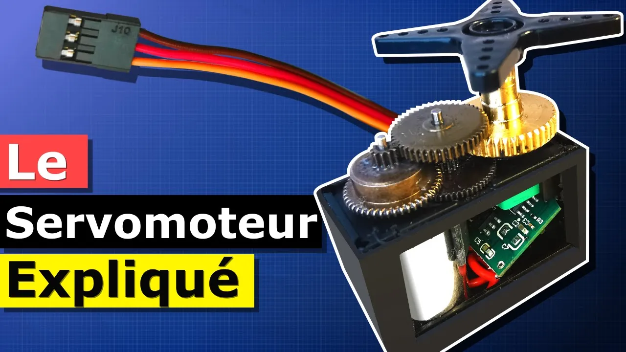
Le Servomoteur Expliqué
276.5K
This section demonstrates how to control a servo motor using an Arduino microcontroller and a potentiometer. The circuit connects the Arduino's 5V and ground pins to the breadboard, with the potentiometer connected between 5V and ground, and its center pin to Arduino's A0 analog input. The servo signal wire connects to Arduino's pin 9. The Arduino code uses the Servo library to create a servo object, declares the potentiometer pin, reads the analog value (0-1023), converts it to a servo angle (0-180 degrees), and sends the command to the servo. This creates a system where turning the potentiometer knob directly controls the servo's position.
Click to watch →

How to Arduino #4 — analogRead, Potentiometers, and map() to Control a Servo
53.3K
This tutorial demonstrates how to read a potentiometer's position using Arduino's analogRead() function, which converts the 0-5V voltage from the potentiometer's wiper into a digital value between 0 and 1023, and then use the map() function to scale this value to control a servo motor's angle from 0-180 degrees, creating a real-time tracking system where the servo follows the potentiometer's knob position.
Click to watch →
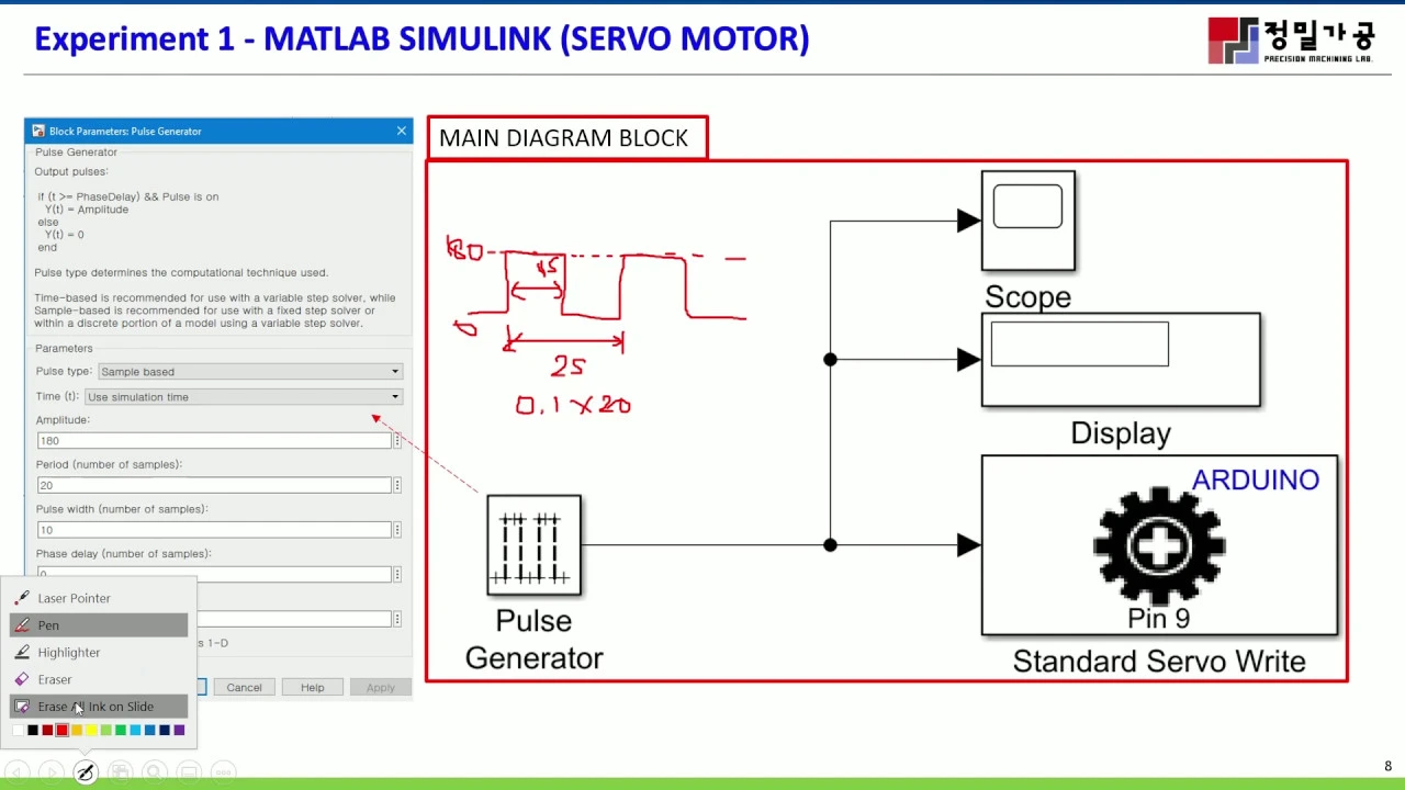
컴퓨터계측및제어 - ARDUINO MATLAB SIMULINK - SERVO and DC MOTOR (14주차)
17.3K
A potentiometer can be used as an analog input device to control servo motor position. The potentiometer provides a voltage proportional to its rotation angle (0-1023 digital value for 10-bit resolution). The Simulink model converts this analog input to an angle value (typically 0-180 degrees) using gain blocks. The converted signal drives the servo motor, allowing manual control of position through the potentiometer knob.
Click to watch →
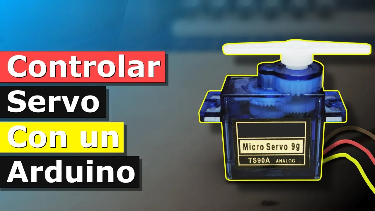
Cómo Controlar un Servo con un Arduino
22.2K
This tutorial demonstrates how to control a servo motor's position using a potentiometer as an input device. The circuit connects the potentiometer between 5V and ground, with its center terminal to Arduino's A0 pin, while the servo motor connects to 5V, ground, and digital pin 9. The Arduino code includes the Servo library, declares a servo object and potentiometer input, reads the analog value from A0 (which ranges from 0 to 1023), and maps this value to servo angles (0-180 degrees) using the map() function. This allows the servo position to change proportionally as the potentiometer knob is rotated.
Click to watch →
Deep Dive
Scaling up to multi-servo systems (e.g., robotic arms, animatronics) using dedicated I2C servo controllers like the PCA9685 to offload PWM generation from the Arduino.

Connect Up To 992 Servos To An Arduino, Using I2C
89.4K
This tutorial demonstrates how to connect up to 992 servos to an Arduino using 16-channel PCA9685 PWM drivers controlled via I2C, where each board can drive 16 servos and up to 62 boards can be chained together, all controlled by just two Arduino pins; the system uses Adafruit PWM Servo Driver library for programming, requires setting minimum/maximum travel limits to prevent servo damage, and enables complex projects like robot arms and LED displays by freeing up Arduino pins and reducing processing load.
Click to watch →
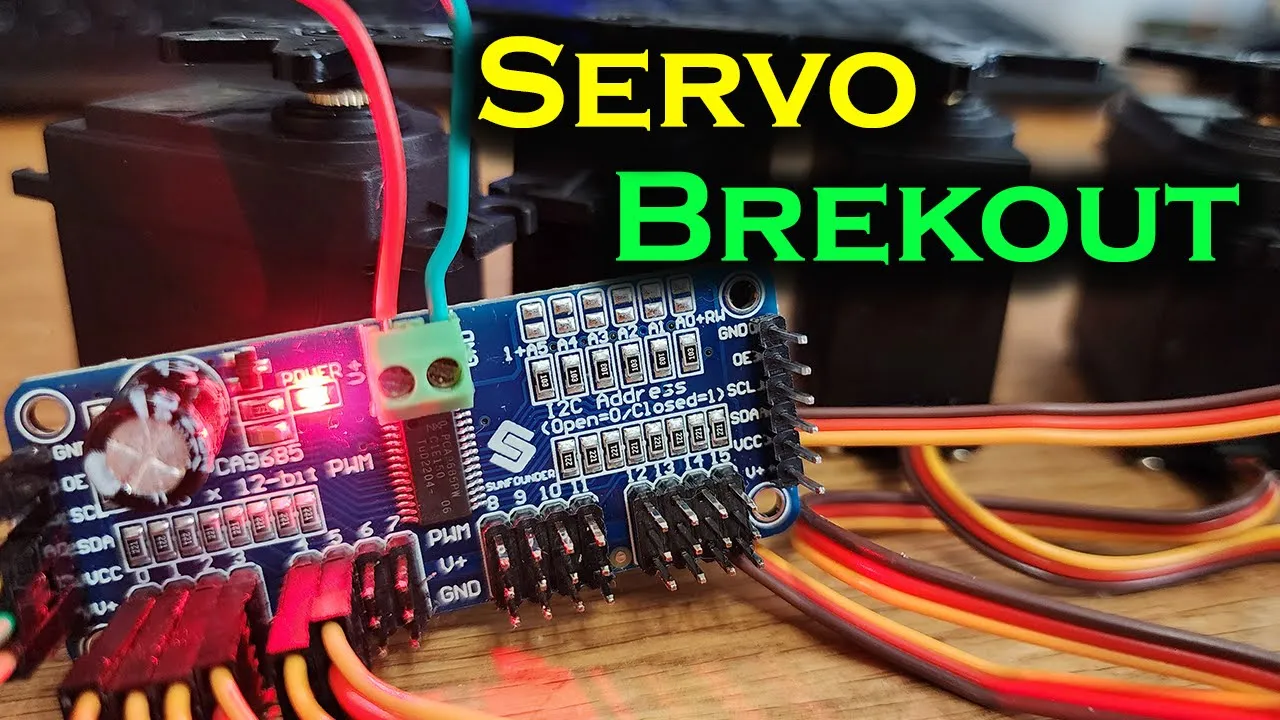
Mastering Servo Control: PCA9685 PWM Driver with Arduino Tutorial and Demo
70.3K
The PCA9685 is a 16-channel PWM driver that enables precise control of multiple servo motors using I2C communication, freeing up the Arduino microcontroller to perform other tasks; it can control up to 16 servos with a single board or chain multiple boards together for 992 total outputs, with each board having a unique I2C address configurable via solder jumpers, and requires external 5V power for the servos while the VCC pin only powers the driver chip.
Click to watch →
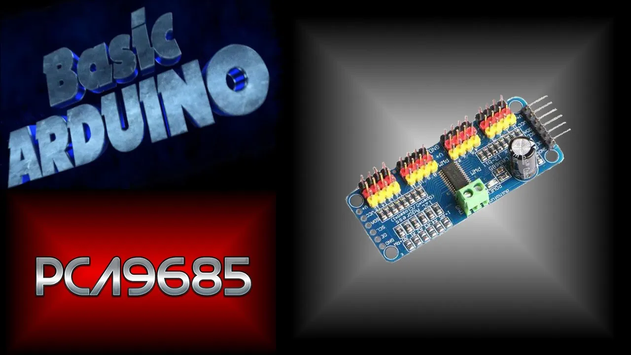
Arduino Servo Control with PCA9685: Step-by-Step Tutorial
32.7K
The PCA9685 is an I2C-based 16-channel PWM controller that extends Arduino's limited PWM capabilities (typically only 6 PWM pins on Uno/Nano/Pro Mini boards) to control up to 16 servos simultaneously, using just two Arduino pins (A4 and A5 for SDA/SCL); the module requires external 5-6V power for servos and can be programmed using the HCPCA9685 library, where servo positions are controlled through numerical values rather than angles, allowing for easy expansion by adding more servo write commands to different output channels.
Click to watch →
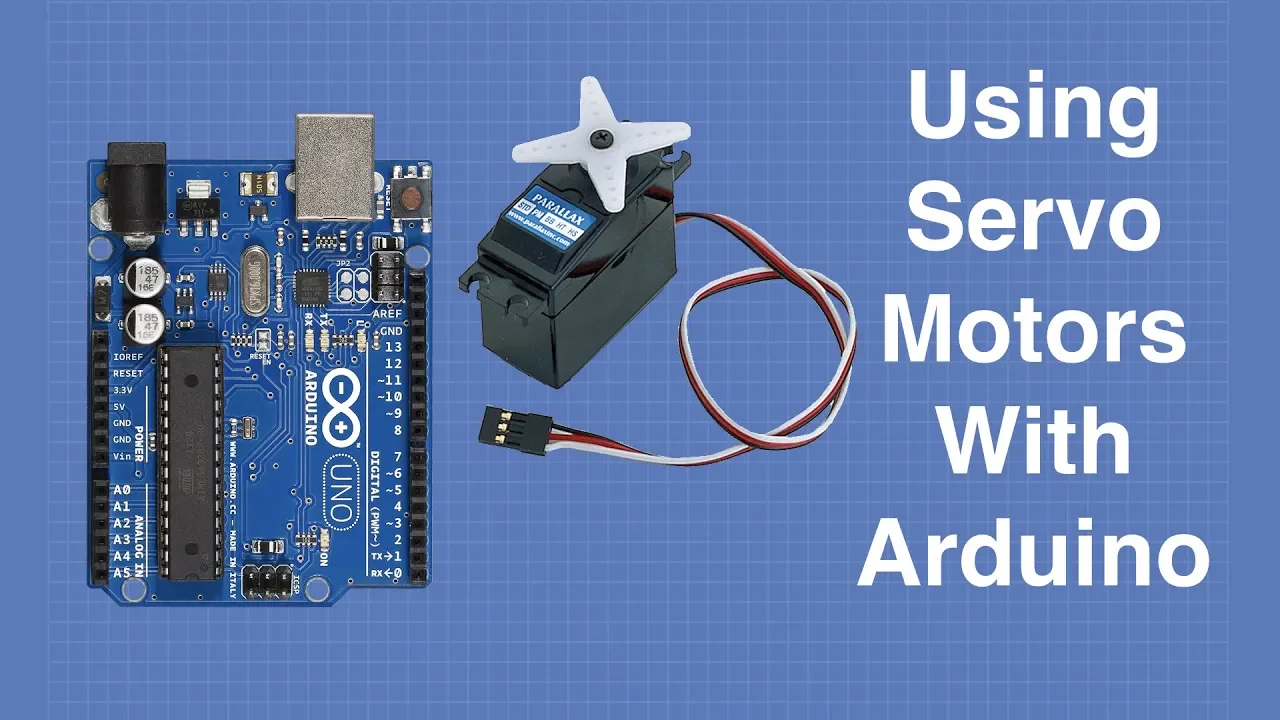
Arduino Servo Motor Control: PWM, PCA9685, and I2C Tutorial
1.5M
Servo motors are motors whose shaft position can be precisely controlled using pulse width modulation (PWM), where a 1.5ms pulse centers the servo at 90 degrees, 1ms moves it to 0 degrees, and 2ms moves it to 180 degrees; hobbyist servos use a 3-pin connector (ground, power, control) and require a separate 5-6V power supply rather than the Arduino's 5V to avoid electrical noise and current spikes. The Arduino Servo library simplifies control with example sketches like Sweep (which sweeps the servo from 0 to 180 degrees) and Knob (which uses a potentiometer to control position). For controlling multiple servos (up to 16 or more), the PCA9685 I2C PWM controller board provides 16 channels of PWM output using just two wires (SCL and SDA) and can be cascaded to control up to 992 servos with one Arduino.
Click to watch →
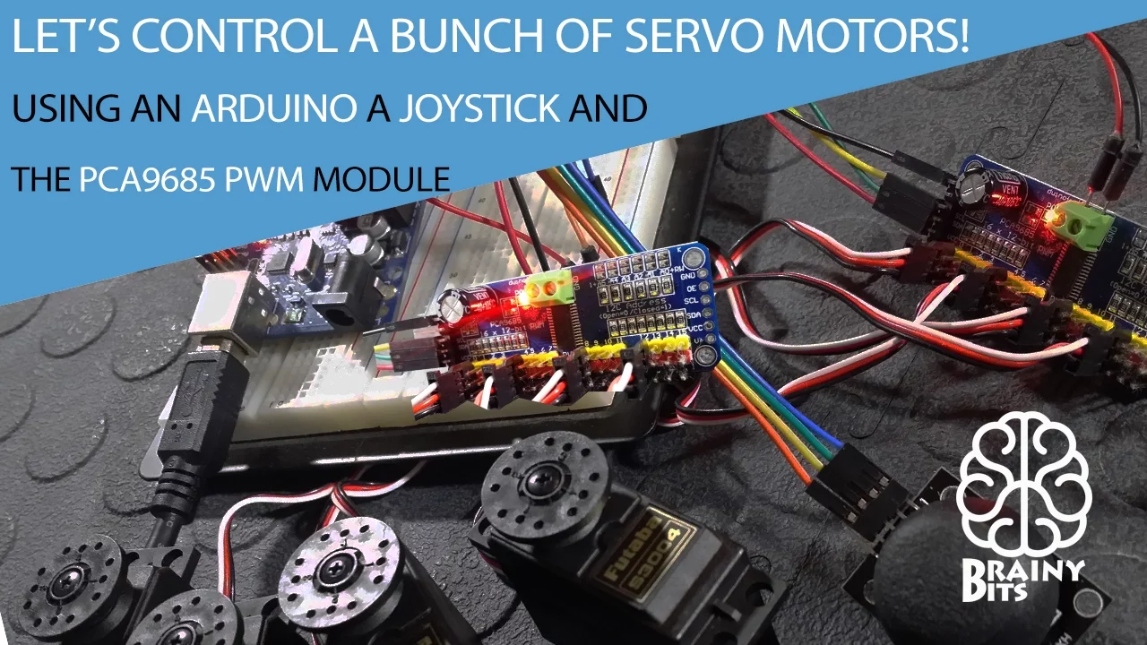
Control a 'LOT' of Servo Motors using a Joystick, Arduino and PCA9685 PWM Module - Tutorial
51.5K
The PCA9685 PWM module enables control of up to 16 servo motors using only 2 pins on an Arduino through the I2C protocol, with an external power supply required to power the servos since they draw more current than the Arduino can provide; the module can be configured in servo mode for motor control or PWM mode for LED control, and multiple modules can be cascaded to control up to 32 servos.
Click to watch →
Deep Dive
Implementing software-based motion profiling, such as acceleration and deceleration curves, to reduce mechanical stress and power surges during rapid movements.

¿Por qué las máquinas vibran cuando aceleramos?: Jerk, estructura y control del movimiento
141
Jerk is the rate of change of acceleration (third derivative of position), representing force changes during motion profile transitions. High jerk values indicate abrupt acceleration changes, corresponding to high-frequency harmonics that stress machine structures. Jerk is the 'language' through which motion control communicates with mechanics—high jerk is like a loud shout that stresses the structure, while low jerk is like a whisper that moves loads smoothly. Trapezoidal profiles have theoretically infinite jerk at corners, while S-curve profiles have bounded jerk and lower harmonic energy. In liquid handling, high jerk causes sloshing that compromises product quality.
Click to watch →

AMC Training Day 2: Positioning
3.3K
Jerk is defined as the rate of change of acceleration, representing how quickly acceleration changes over time. In motion control, jerk control (referred to as S-curve profiling) is essential for protecting fragile mechanical components such as ball screws, gearboxes, and belts/pulleys. Jerk reduces the negative effects of mechanical backlash in systems with sloppiness from gearing or belt stretch. The AMC implements jerk through four parameters in Menu 38: Parameters 11, 12, 13, and 14 correspond to the four transition points in a trapezoidal profile—initial acceleration, transition from acceleration to steady state, transition from steady state to deceleration, and transition from deceleration to rest.
Click to watch →

Harmonic Actuator RDrive 60 (Rozum Robotics)
48.4K
S-curve motion profiles limit acceleration and velocity during position changes to reduce mechanical stress and improve smoothness. The profile consists of acceleration phase, constant velocity phase, and deceleration phase. The set_position_with_limits command allows specifying maximum speed and acceleration parameters for controlled motion.
Click to watch →

Motion Profiles: S-curve motion planning tips and tricks | Limited Jerk (part 5)
647
S-curve motion profiles, which modulate acceleration to eliminate infinite jerk at transitions (unlike T-curves with constant acceleration), theoretically reduce mechanical stress but often underperform T-curves in real-world rigid, high-speed automation applications due to uneven acceleration distribution requiring higher peak torque; practical experience in semiconductor and robotics shows T-curves consistently outperform S-curves when time constraints are fixed, despite vendors promoting S-curves for smoother motion.
Click to watch →

Virtual Lunch & Learn: Motion Analyzer Software
2.1K
The motion profile editor allows creation of multi-segment motion profiles with: (1) Trapezoidal profile templates (one-third acceleration, one-third constant velocity, one-third deceleration); (2) Customizable move distances and times; (3) Velocity limit enforcement to prevent exceeding mechanical constraints; (4) Dwell time insertion for stationary periods; (5) Direction reversal capability for bidirectional motion; (6) Real-time velocity profile visualization showing peak speeds.
Click to watch →
Deep Dive
Exploring closed-loop feedback systems and PID control theory to achieve higher precision and load compensation in heavy-duty motion applications.

Expt 6# CLOSED LOOP SPEED CONTROL OF DC MOTOR USING PID CONTROLLER# Matlab/Simulink Model#Drives Lab
68.2K
This segment demonstrates practical implementation of PID control for motor speed regulation. The system initially exhibits steady-state error and slow response. By tuning proportional (KP) and integral (KI) gains, the settling time improves dramatically—from over 2 seconds to approximately 0.3 seconds. The video shows how increased mechanical load torque causes speed reduction in open-loop systems but is automatically compensated in closed-loop control through automatic voltage adjustment. This demonstrates the fundamental advantage of feedback control: maintaining desired speed despite disturbances like changing loads, making the system robust and reliable for industrial applications.
Click to watch →

We Took Our Etch-A-Sketch Robot to OpenSauce
159.8K
This video demonstrates how an Etch-a-Sketch robot was engineered to draw over 1,000 pictures daily by implementing PID control theory (Proportional, Derivative, and Integral controllers) to achieve precise cursor movement, and by measuring and compensating for mechanical backlash (lost motion) in the device's mechanism, which was found to be approximately 7 milliradians or 1.66mm.
Click to watch →

Lec-1 Introduction to control problem
566.8K
A closed-loop feedback control system structure includes a sensor that measures the controlled variable and feeds this information back to the controller. The controller compares the actual controlled variable (from the sensor) with the command signal to generate an error signal. This error signal is then used to generate a suitable control signal that manipulates the plant input. This creates an error self-nulling process where the controller action reduces the error to zero. The system is called closed-loop because the loop is closed through the feedback path, allowing the controller to respond to both command signals and disturbances indirectly through the controlled variable measurement.
Click to watch →

Nebulus RS6 goes 1.000 HP Teil 4: Finale & 100-200 km/h
30.8K
Closed-loop turbo control continuously monitors actual boost pressure and adjusts wastegate position accordingly. PID (Proportional-Integral-Derivative) parameters control this regulation: proportional responds to current error, integral addresses accumulated past errors, and derivative predicts future error. Properly tuned PID prevents oscillation (pendulum effect) where boost fluctuates between high and low values. Optimal tuning results in smooth, stable boost regulation with minimal overshoot.
Click to watch →

Intro to Control - 11.3 PID Control Example
262.1K
To derive the closed-loop transfer function with PID control, multiply the controller transfer function GC by the plant transfer function GP and divide by (1 + GC*GP). For the specific plant 1/(s-2) and PID controller (KD*s^2 + KP*s + KI)/s, the resulting closed-loop transfer function is [KD*s^2 + KP*s + KI] / [s^2 + (KP-2)*s + (KI + 1)]. This shows how the controller coefficients affect the system dynamics.
Click to watch →
Servo Setup
Code Example
Sweep Motion
Signal Settings
Working Demo
Servo Setup
0:01- 1
Greetings and introduction to the tutorial.
- 2
Identify the Arduino and servo motor in use.
Limitations of Direct PWM Control: The Case for Analog Control and Closed-Loop Feedback
While controlling a high-torque ASME-03 servo using standard PWM signals from an Arduino Uno is a common hobbyist approach, it has significant limitations in practical, high-load applications. Standard 8-bit PWM lacks the resolution required for precise positioning of heavy loads, often resulting in jitter, overshoot, and holding-current instability. Furthermore, standard RC PWM is an open-loop control method, meaning the Arduino cannot receive feedback regarding the servo's actual position, temperature, current draw, or stall status. For high-torque applications, engineers advocate for alternative control methods. The ASME-03 often performs more reliably when controlled via a smooth Analog Voltage (0-5V) signal rather than digital PWM pulses. Additionally, for robust industrial tasks, transitioning to closed-loop communication protocols (such as RS-485 or CAN-bus) with smart servos is preferred. These systems provide real-time diagnostic feedback, ensuring the controller can detect stalls or mechanical overloads, thereby preventing hardware damage and ensuring system safety.
Basic Arduino programming and familiarity with the Arduino IDE, including uploading sketches and utilizing standard libraries like 'Servo.h'.
Fundamental concepts of Pulse Width Modulation (PWM) and how duty cycles translate to absolute positioning (0 to 180 degrees) in servo motors.
Understanding the necessity of external power supplies for high-torque, high-current motors (like the ASME-03) to prevent damaging the Arduino Uno board.
Basic electrical circuit principles, including voltage, current, common ground configurations, and safety practices for handling high-current electronics.
Integrating physical input devices, such as potentiometers or joysticks, to dynamically control the angular position of the high-torque servo.
Scaling up to multi-servo systems (e.g., robotic arms, animatronics) using dedicated I2C servo controllers like the PCA9685 to offload PWM generation from the Arduino.
Implementing software-based motion profiling, such as acceleration and deceleration curves, to reduce mechanical stress and power surges during rapid movements.
Exploring closed-loop feedback systems and PID control theory to achieve higher precision and load compensation in heavy-duty motion applications.
9.7K views59likes1:27@irfonergi14Original Release: 2017-05-15
as-salam-o-alaikum I guess this is a cell for Timor use the Arduino and ask me 0 tracer for hike Torcy torsion and then we know that it can be used properly this is this game only that use the example from Arduino and maybe you can feel the programs this is the programs [Music] we move the protect the surf for at the 180 degrees from 0 to 80 one 180 degrees is we use 20 I'm sorry 12 fault for sampling [Music] and it works properly okay in jail
Up Next

68:34
Electronic Circuits Explained: Components & Ohm's Law
@RealLetsFindOut
128.2K views•2019-04-07

12:54
Triumph of Orthodoxy Icon: Byzantine Art & History Explained
@BenCallan
2.1K views•2024-08-06

9:49
FastAPI vs Flask vs Django: Choosing the Right Python Web Framework
@TechWithTim
302.5K views•2024-05-26

1:42
Game of Thrones Opening Credits: A Cinematic Analysis
@gameofthrones
46.3M views•2011-04-18
Related Study Plans & Knowledge Roadmaps
Structured learning paths in General & Interdisciplinary Studies
general-studies
Elevator Engineering: History, Physics & Cities
01From Hoists to Safety Brakes: The Dawn of Vertical Lift
02Hydraulic vs. Traction: The Engineering Physics of Elevators
03Modern Speed, Safety, and Algorithms
+ 2 more learning modules
12h5 modules
Explore Roadmap
general-studies
Rubber: Material Science, History & Geopolitics
01Origins of Natural Rubber & Mesoamerican History
02The Chemistry of Natural Rubber & Vulcanization
03The Geopolitics of the Rubber Boom & Colonization
+ 2 more learning modules
12h5 modules
Explore Roadmap
general-studies
Containerization: Evolution, Logistics & Trade
01Ancient Trade & Bulk Cargo: Amphorae to Barrels
02The Industrial Revolution & Cardboard Packaging
03The Containerization Revolution: Malcom McLean
+ 2 more learning modules
12h5 modules
Explore Roadmap
general-studies
Textile Tech: Evolution, Labor & Global Impact
01Pre-Industrial Textiles: Handloom & Cottage Industry
02Mechanization: The Spinning Jenny to the Power Loom
03The Factory System & Global Labor Transformation
+ 2 more learning modules
10h5 modules
Explore Roadmap