




![[EET 1015C - Fundamentals of DC Circuits] Setting Up a Simple DC Circuit on the Breadboard](https://i.ytimg.com/vi/9R0H_p17HMw/maxresdefault.jpg)









![8서보 4족보행 로봇 만들기_[반지하공작실]](https://i.ytimg.com/vi/Dk4DLiQ2pvc/hqdefault.jpg)

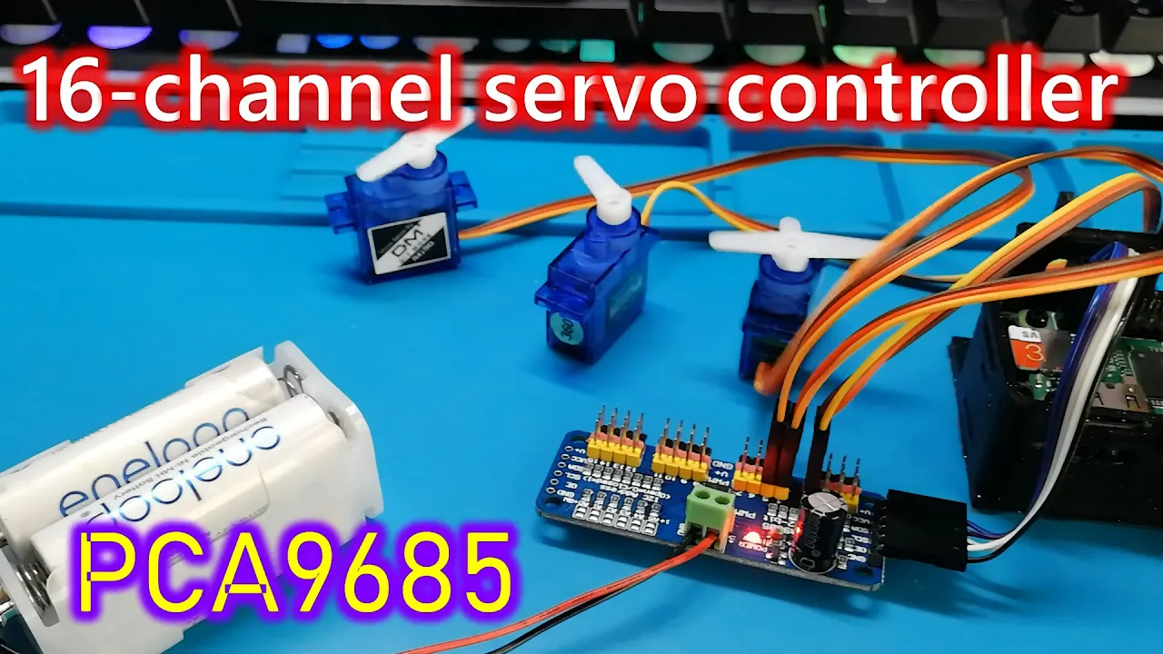

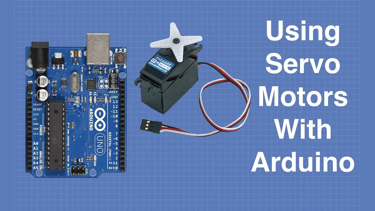
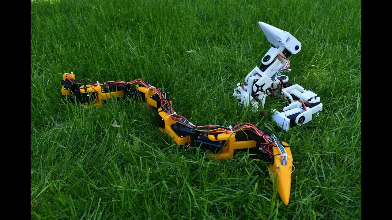
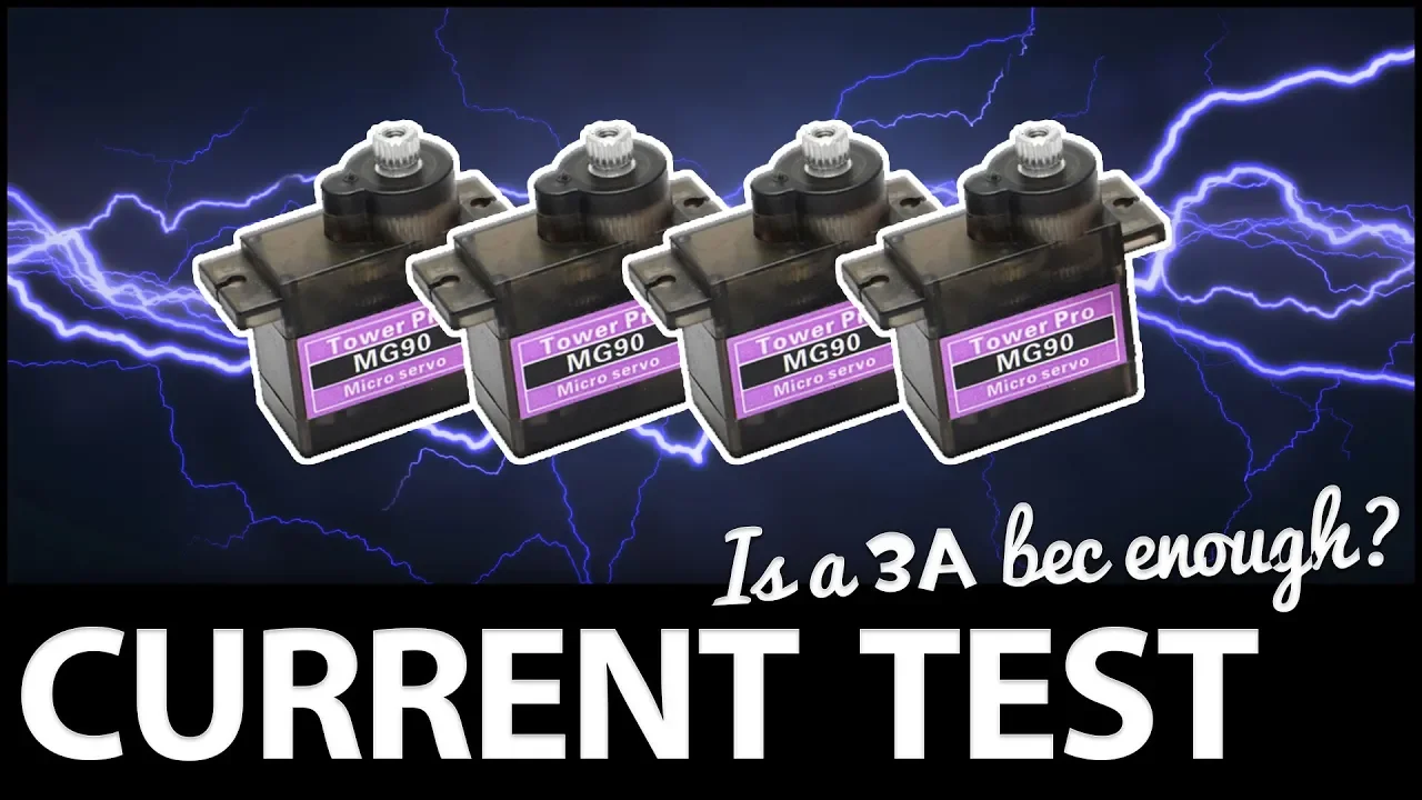




The PCA9685 is an I2C-based 16-channel PWM controller that extends Arduino's limited PWM capabilities (typically only 6 PWM pins on Uno/Nano/Pro Mini boards) to control up to 16 servos simultaneously, using just two Arduino pins (A4 and A5 for SDA/SCL); the module requires external 5-6V power for servos and can be programmed using the HCPCA9685 library, where servo positions are controlled through numerical values rather than angles, allowing for easy expansion by adding more servo write commands to different output channels.
Arduino Servo Control with PCA9685: Step-by-Step Tutorial
Added:Basic familiarity with the Arduino IDE, writing simple sketches, and uploading code to a microcontroller.
Understanding how servo motors operate, including the concepts of Pulse Width Modulation (PWM) and duty cycles.
Fundamentals of basic DC circuits, including breadboard wiring, common ground principles, and the need for external power sources.
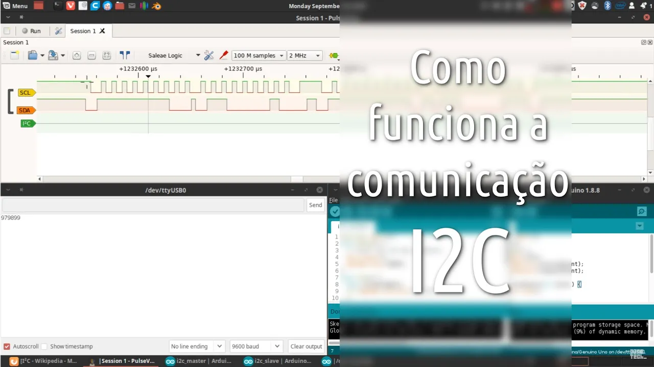
An introductory conceptual understanding of the I2C communication protocol (specifically SDA and SCL lines).
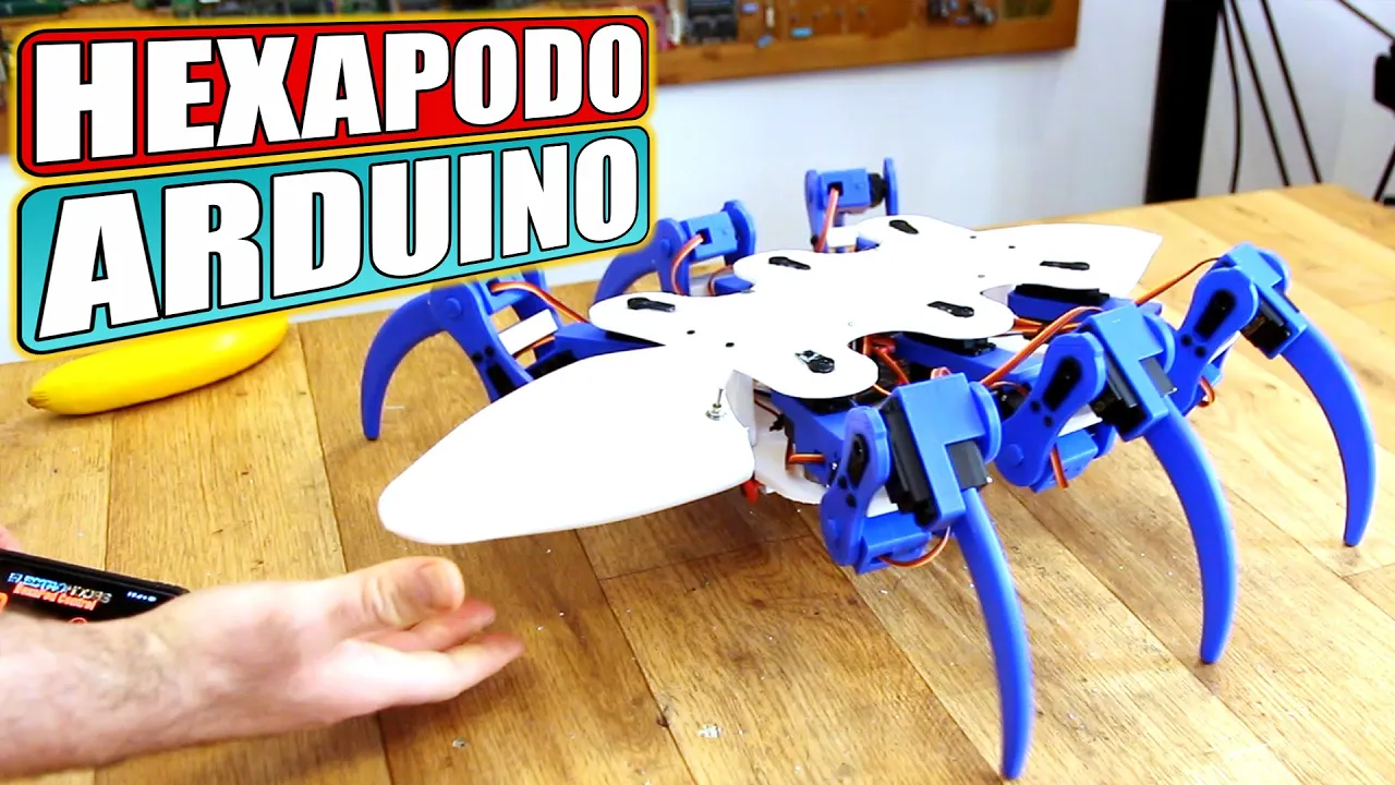
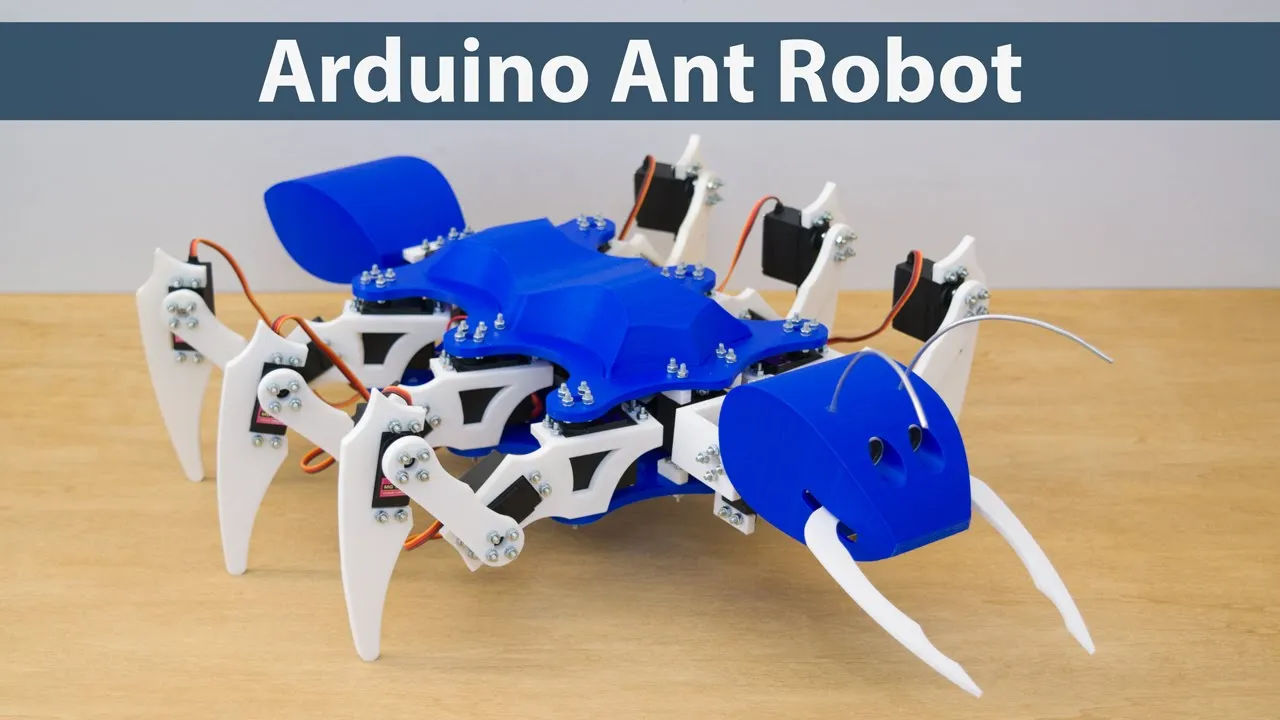
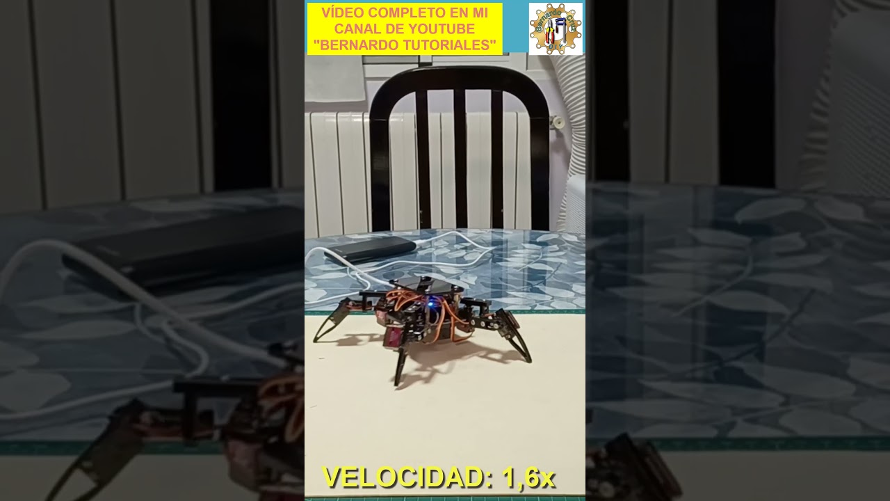
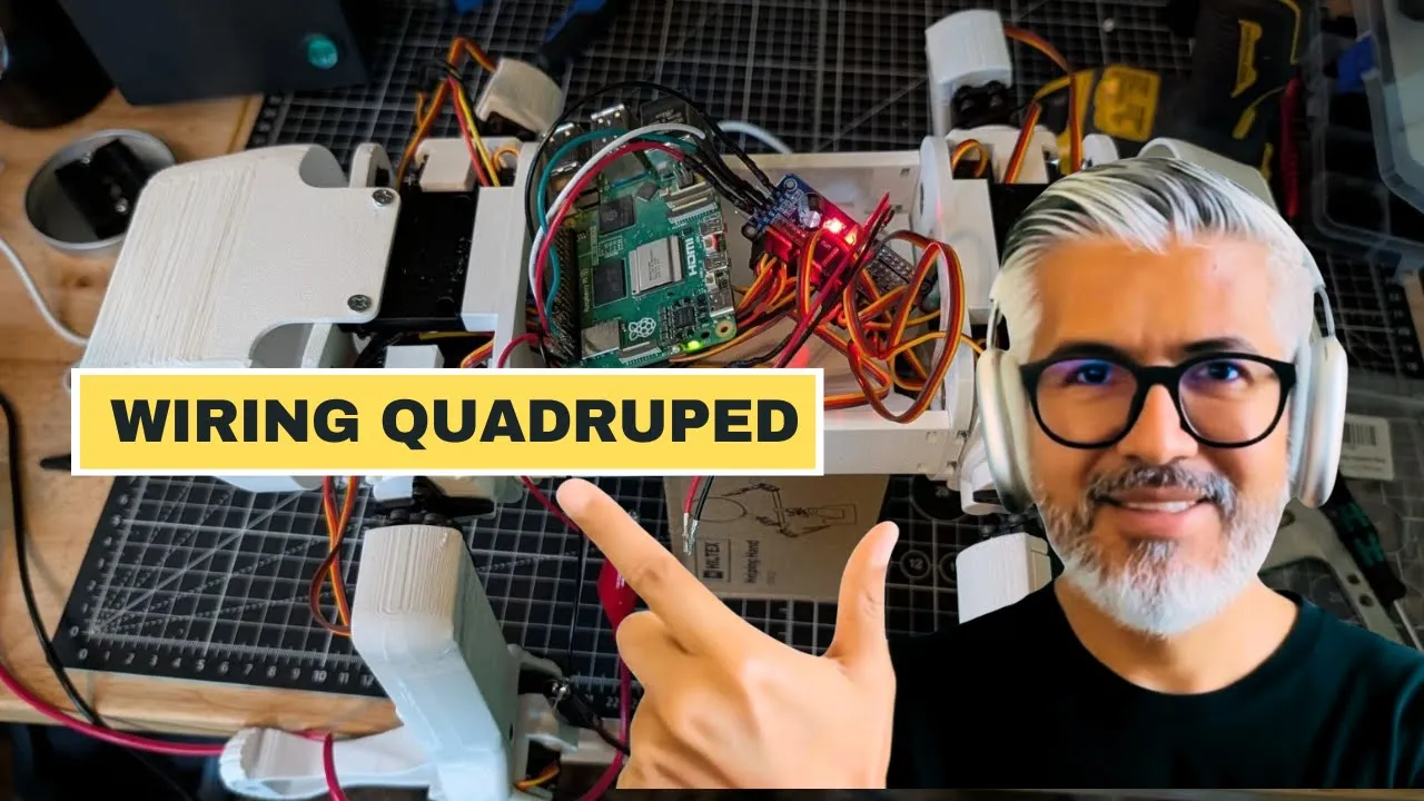
Designing and programming multi-servo robotics projects, such as a robotic arm, a hexapod, or a quadruped walker.
Implementing I2C cascading by daisy-chaining multiple PCA9685 modules together to control up to 992 servos.
Advanced power management, including calculating maximum current draw for multiple servos and selecting appropriate batteries or regulators.
Optimizing motion profiles and inverse kinematics (IK) to achieve smooth, coordinated movements across multiple joint axes.
32.7K views492likes8:31Original Release: 2020-06-12
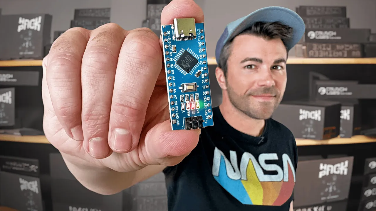
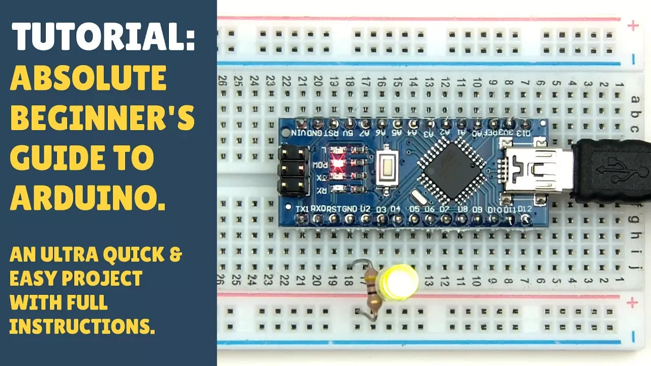
[Music] hello on this episode of basic Arduino we will look at how you can control up to 16 servos with your Arduino using a PC a 96 85 module Arduino Uno Pro minis and nanos only have 6 PWM pins that you can use for controlling servos but by adding one of these modules you can control up to 16 servos you can add multiple PC a 96 85 modules to control even more servos but for this tutorial we will stick with just one also this module uses I to see communication so it only takes up two of your Arduino spins a4 and a5 the first thing we need to do is connect our PC a 96 85 module to our Arduino board so let's get started for this tutorial I will be using an Arduino Nano but pro minis and Ono's will also use the same connections if you are using an Arduino mega the connections will be different but we will cover them all so for this tutorial I will be using two servos but when we get to the Arduino sketch I will show you how to add more first connect VCC on the PC a 96 85 module to the Arduino 5 volt pen next connect SDA to a 4 if you are using in our green Omega connect to pin 20 instead SCL goes to 85 if you're using an Arduino mega once again connect this to pen 21 instead Oh II is not used connect the grounds between the PC a 96 85 and the Arduino next we will connect the two servos 1 to position 3 and the other to position 8 to power the Arduino I will be using a 9 volt battery so I will connect the positive from the battery to the VI n on the Arduino board and the ground-to-ground if you are using a regulated five volt power supply you can go ahead and connect yours to the five volt pen on your green Oh instead next we need to power the servos the output from your adrenal board will not drive that many servos so an external power supply will be necessary it needs to be between five and six volts more than six volts will damage the servos please use a voltmeter to check the power supply you are going to use it may say five or six volts on it but more than likely it will put out more than that and would then damage your servos for this tutorial I am only using two servos and only for a short amount of time therefore I can avoid using the external power source and go ahead and instead connect the VCC from the PC a ninety six eighty five to the 5 volt pin of my Arduino if you go ahead and try this please remember not to run it for very long or you may overheat and damage the Arduino board once you have everything connected it should look something like this now let's move on to the sketch the first thing we will need to do is get the library that we will be using I tried out the Adafruit library that most people use but found that the HCP see a 96 85 library is much easier to use and just as powerful if you look in the description below you will find the link to this projects web page where you can download it after you download it open up your Arduino IDE click on sketch and under the include library tab select add zip library navigate to where you downloaded the library to and select it now that the library is installed click on file under the examples tab scroll down until you find h c pc a 96 85 and select the servo example before we go over how the sketch works let's try it out and make sure everything's working scroll down the sketch until you find these two lines of code in the void loop change both of the zeros to threes then go ahead and upload the sketch to your Arduino if everything is connected correctly your serve all connected to position 3 on the PC 896 85 should be sweeping back and forth like this now that we have it working let's go over call the sketch works and how to add more servos to it to start with we are including the HC TC a 96 85 library then we are defining the i2c address of the PC a 96 85 module the default address of the module is 0 X or 0 next we are creating an instance of the library naming it and setting the address moving on to the void setup we are first initializing library and setting it to servo mode then we are waking up the PC a 96 85 by setting the sleep mode to false moving along to the void loop we start by setting up an integer to store the servos position then we have two for loops to sweep the servos position up and down unlike the servo library that is included with your arduino ide this library uses positions for the servo instead of the angle of the servo you may need to increase or decrease these numbers a little bit for your particular circle for the 9 gram servo I am using the default 10 minimum and 450 maximum works fine the first for loop sweeps the servo up from position 10 to position 450 with a 10 millisecond delay between positions the second for loop does the opposite sweeping the servo down from position 450 to position 10 with a 10 millisecond delay between each position if you would like the servos to sweep faster or slower just change the delay time in both of the loops now that we have went over the example sketch let's look at how we can add more servos in the void loops first for loop you will find this line of code this is the code that defines which servo you want to write to and what value you want to write to it this number defines the position on the PC 896 85 you want to write 2 right now it is set to position 3 next we declare the value we want to write to the servo POS is writing the value currently stored in the POS integer to the servo two we add another serval just copy this line of code and paste it right below then simply change the three that was defining position 3 on the PC a 96 85 to 8 this will now write to the servo on position 8 next do the same thing in the second for loop now instead of just one servo sweeping back and forth both servos will sweep let's upload the sketch to our Arduino and try it out that will conclude this episode of basic Arduino if you would like to learn how to use more than one PC a 96 85 module with your Arduino board to control even more servos plus some other tips and tricks for the module look in the description below for a link to that video thank you for joining us here today for this episode of basic Arduino please remember to Like share and subscribe
Up Next

6:22
How to Power and Wire 16 Servos with PCA9685 for Arduino
@BMonsterLaboratory
11.7K views•2025-02-09

12:54
Triumph of Orthodoxy Icon: Byzantine Art & History Explained
@BenCallan
2.1K views•2024-08-06

9:49
FastAPI vs Flask vs Django: Choosing the Right Python Web Framework
@TechWithTim
302.5K views•2024-05-26

1:42
Game of Thrones Opening Credits: A Cinematic Analysis
@gameofthrones
46.3M views•2011-04-18
Related Study Plans & Knowledge Roadmaps
Structured learning paths in General & Interdisciplinary Studies
general-studies
Elevator Engineering: History, Physics & Cities
01From Hoists to Safety Brakes: The Dawn of Vertical Lift
02Hydraulic vs. Traction: The Engineering Physics of Elevators
03Modern Speed, Safety, and Algorithms
+ 2 more learning modules
12h5 modules
Explore Roadmap
general-studies
Rubber: Material Science, History & Geopolitics
01Origins of Natural Rubber & Mesoamerican History
02The Chemistry of Natural Rubber & Vulcanization
03The Geopolitics of the Rubber Boom & Colonization
+ 2 more learning modules
12h5 modules
Explore Roadmap
general-studies
Containerization: Evolution, Logistics & Trade
01Ancient Trade & Bulk Cargo: Amphorae to Barrels
02The Industrial Revolution & Cardboard Packaging
03The Containerization Revolution: Malcom McLean
+ 2 more learning modules
12h5 modules
Explore Roadmap
general-studies
Textile Tech: Evolution, Labor & Global Impact
01Pre-Industrial Textiles: Handloom & Cottage Industry
02Mechanization: The Spinning Jenny to the Power Loom
03The Factory System & Global Labor Transformation
+ 2 more learning modules
10h5 modules
Explore Roadmap